Panduit FMPS and Cisco Implementation Guide
Available Languages
Bias-Free Language
The documentation set for this product strives to use bias-free language. For the purposes of this documentation set, bias-free is defined as language that does not imply discrimination based on age, disability, gender, racial identity, ethnic identity, sexual orientation, socioeconomic status, and intersectionality. Exceptions may be present in the documentation due to language that is hardcoded in the user interfaces of the product software, language used based on RFP documentation, or language that is used by a referenced third-party product. Learn more about how Cisco is using Inclusive Language.
- US/Canada 800-553-2447
- Worldwide Support Phone Numbers
- All Tools
 Feedback
 Feedback
Centralized Power Architecture
Test Case With Cisco Catalyst 9300
Catalyst 9300 Power Supply Configurations
Operation of Cisco Catalyst 9300
Design Architectures And Tests Outcome
Distributed Network Architecture With Centralized Power
Test 1: FMPS to Single DC Power Supply on 9300
FMPS Management Interface Screenshots for Powering 15-Watt Endpoints
FMPS Management Interface Screenshots for Powering 90-Watt Endpoints
Catalyst 9300 Show Command Outputs for Powering 15 Watts
Catalyst 9300 Show Command Outputs for Powering 90 Watts
Test 2: FMPS to Dual DC Power Supplies on C9300
FMPS Management Interface Screenshots for Powering 15 Watt Endpoints
FMPS Management Interface Screenshots for Powering 90 Watt Endpoints
Catalyst 9300 Show Command Outputs for Powering 15 Watts
Catalyst 9300 Show Command Outputs for Powering 90 Watts
Centralized DC Power Back-Up For Power Redundancy
Test 3: FMPS to DC Power Supply as Backup
Test 3 with 15-Watt Endpoints and Two Power Supplies
Test 3 with 15-Watt Endpoints and Loss of AC Power Supply
Test 3 with 90-Watt Endpoints and Two Power Supplies
Test 3 with 90-Watt Endpoints and Loss of AC Power Supply
Dual Homing Power And Network Architecture
Test 4: FMPS to DC Power Supply in Dual Homing Configuration
Test 4 with 15-Watt Endpoints and Two Power Supplies
Test 4 with 15-Watt Endpoints and Loss of One DC Power Supply
Test 4 with 90-Watt Endpoints and Two Power Supplies
Test 4 with 90-Watt Endpoints and Loss of One DC Power Supply
By combining Cisco's industry-leading Catalyst 9300 PoE switching platform with Panduit's UL-1400-1 certified Fault Managed Power System, we've created a comprehensive solution that has been engineered and validated to meet rigorous standards of performance, safety, and reliability while supporting organizations' sustainability and cost optimization goals
This architecture validation ensures partners can integrate the solution efficiently, reducing implementation time and risk. This is particularly important as the solution introduces new capabilities such as delivering up to hundreds of watts per copper pair over distances exceeding 1km while maintaining UL-1400-1 compliance. The detailed engineering validation and documentation provides the technical foundation for integrating building management systems with IT networks, establishing a standards-based infrastructure for power distribution and network connectivity.
The test cases covered in this document have been validated in a collaborative effort between Panduit and Cisco to show that FMPS can be implemented successfully to power Cisco’s Catalyst switches with direct current (DC) power. The FMPS can power a DC power supply in a PoE solution to serve multiple purposes that include, but are not limited to:
● Serve as the primary power delivery to one or both power supplies on a PoE switch
● Serve as a backup solution to a brownfield PoE deployment with an existing power supply
● Serve as a supplementary delivery solution that requires additional power to a switch
The intended audience for this document is for all parties involved in purchasing, designing, and implementing a PoE solution with Panduit’s FMPS, including but not limited to the following:
● project and/or account managers
● MEP (mechanical, electrical, plumbing) engineers and/or partners
● system integrators
● installers
● supply vendors
The Panduit FMPS delivers DC power over long distances to remote equipment.
The Panduit FMPS uses Pulse Current as its power delivery method. The Transmitter converts standard alternating current (AC), into a touch-safe pulse current waveform delivered over a Class 4 multi-conductor copper cable to the Receiver. The Receiver converts the pulse current waveform into +/- 48 VDC power, which can power the necessary devices.
For more information on Class-4 / FMP, see National Electric Code (2023) Article 726.
The following section will outline the individual components of the FMPS.
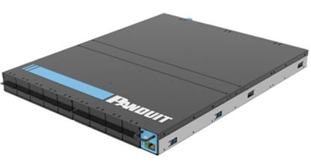


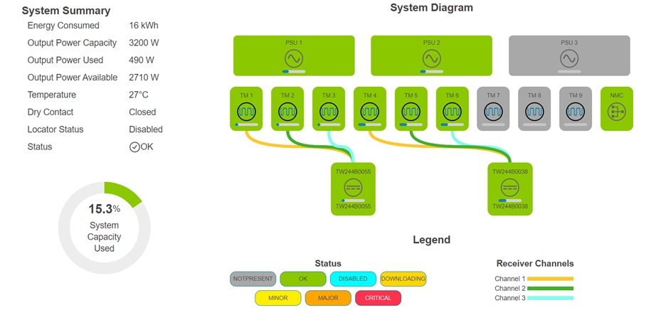
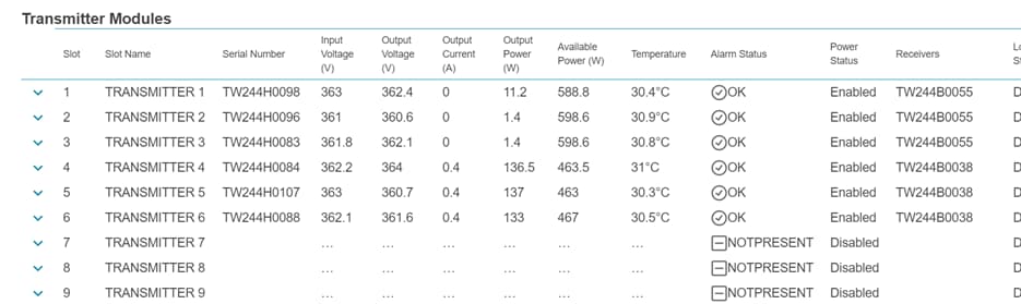
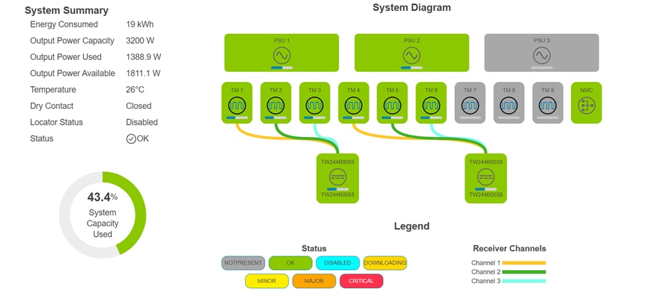
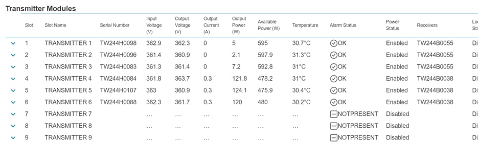
The chassis has an RJ-45 network interface card in the front where an IP address can be configured to gain access to the graphical user interface where an administrator can manage and monitor the entire FMPS. Supported communication protocols are SNMP versions 2 and 3, and Rest APIs are also supported to allow third party applications, services, and tools to interface with the FMPS. Parameters that can be monitored from the management dashboard include temperature, voltage, current, power consumption, and power capacity.
Each component of the FMPS, the Receiver, Transmitter, and power supply, can all be remotely powered on or off through the management interface to service the needs of the administrator.
Additional information about the FMPS chassis can be found at:
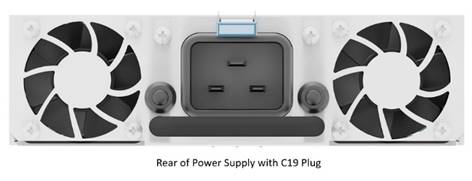
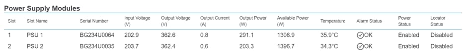
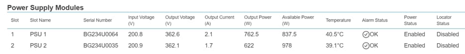
The power supplies are mounted in the rear of the chassis and is supplied with power through a cable connected from the C19 plug in the rear to a source such as a wall outlet or power distribution unit. Each power supply can receive up to 1600 watts, so a chassis with all three bays mounted can receive up to 4800 watts in total. It converts the AC power to 360-volt DC power and delivers it to the Transmitter modules.
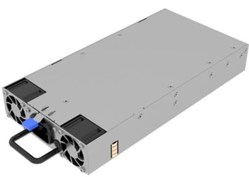
Additional information about the FMPS power supply can be found at:
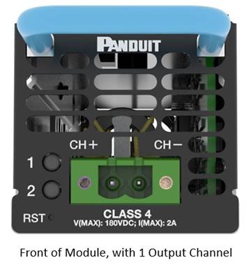
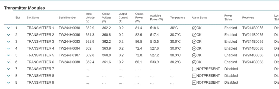
The Transmitter is mounted to the front of the FMPS chassis, where up to 9 modules can be connected. These modules output pulse current which can be terminated to a multiconductor cable. The topic Cable addresses the Class 4 cables used in FMPS.
FMPS uses pulse current and delivers in the namesake pulses, with each cycle lasting around 3 milliseconds. Each cycle has 1 millisecond where a safety check is conducted, and 2 milliseconds where it is delivering power.
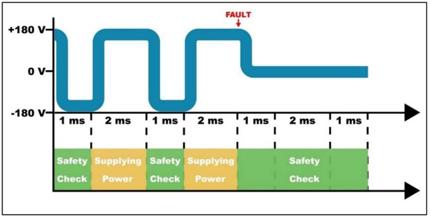
The intent of delivering power in this fashion is to allow the FMPS to detect any faults in the circuit and to respond to the check accordingly. UL-1400-1 outlines the faults that must be addressed, and Panduit has designed the solution accordingly.
Each Transmitter module can output up to 600 watts of power at the source through Class 4 multi-conductor cables of varying gauges. The expected wattage at the termination on the Receiver will be addressed in the topic Distance/Length of Cables, later in this document.

Additional information about the FMPS Transmitter can be found at:
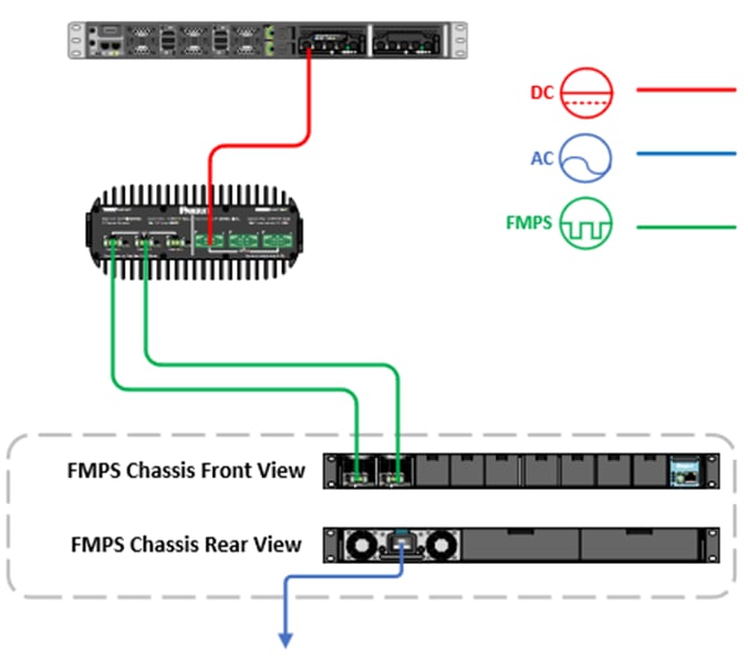
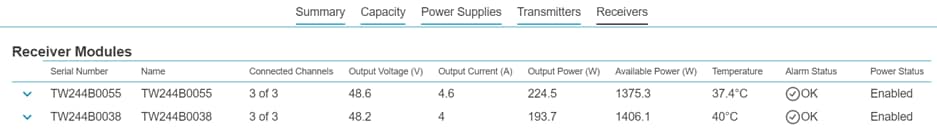
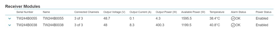
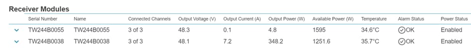
The Receiver connects to the Transmitters via screw terminal plugs that connect to one of the three input channels available on the unit. The Receiver will draw the pulse current and convert it to traditional 48-volt DC power to output 600 watts from a single Transmitter module, or up to 1600 watts from three Transmitter modules, using the available output channels.
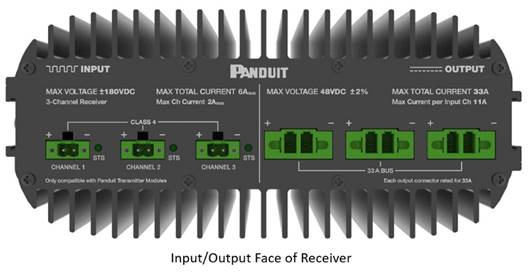 |
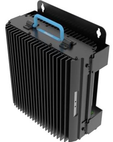
The Receiver has brackets built into the unit that will allow it to be mounted in various locations such as racks, enclosures, and other locations that can sustain and support the required operational environment.
Additional information about the FMPS Receiver can be found at:
Panduit has a product portfolio of enclosures to support the deployment of Receivers and accompanying devices such as PoE switches to enable a plethora of use cases. The enclosures can be modified with modules such as fans, cable management systems, and other components to meet the requirements necessitated by the use case.
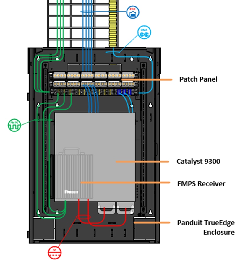
Panduit TrueEdge™ Vertical Wall Mount Enclosure, 6RU, Black, WME6BL shown. Additional information about enclosures from Panduit can be found at:
https://www.panduit.com/en/products/cabinets-thermal-management-racks-enclosures.html
The cable in an FMPS solution connecting the Transmitter to a Receiver is a crucial part of the overall solution. It will be delivering the current from the headend or MDF, where the FMPS chassis is centrally located, to the remote location where the Receiver is.
The cable connecting the FMPS Transmitter to the Receiver is essential, as it carries current from the headend/MDF where the FMPS chassis is located to the remote Receiver site.
Panduit manufactures a line of 3-pair 16-gauge copper cables that were designed to meet the requirements outlined in UL1400-2 class 4 standards. To meet the UL 1400-2 requirements, the cables must be tested to meet several criteria including but not limited to the following:
● Operating temperatures
● Insulation thickness
● Cable gauge range
● Part numbering for manufacturers
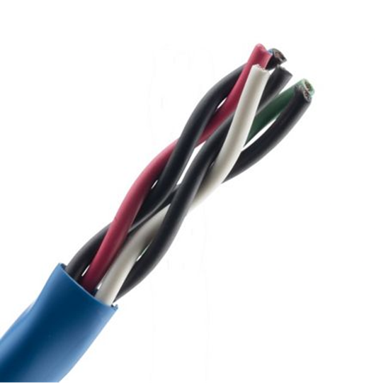
Additional information about Panduit’s 3-pair 16-gauge Class 4 multiconductor cable can be found at:
Regardless of the architecture and design of the power delivery infrastructure where FMPS would be implemented, there are benefits to the solution that are gained almost universally.
The cost to install Class 4 FMPS is lower in comparison to installing other power delivery solutions due to the reduced labor costs for installers, as well as reduced costs in materials.
Due to the built-in safety, the Class 4 FMPS can be installed using Class 2 wiring methods, making it a faster and easier to install power solution compared to a traditional Class 1 circuit. The same low voltage labor installing data cables to the switch can be leveraged to install the Class 4 FMPS cables in the same data cable pathways at minimal additional cost. In comparison, a Class 1 Circuit requires licensed electricians to install conduit and run the electrical wiring separate from the data cables.
Material costs are also reduced by installing Class 4 FMPS cables to the required locations using the same cable pathways for data cables. In comparison, a Class 1 circuit required the installation of conduits, gang boxes, circuit breakers, and outlets for each location. As for PoE cabling, bringing the switch closer to the endpoints significantly reduce the required length of ethernet cabling to connect the switch to the endpoints.
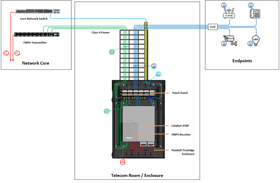
Centralized Power Architecture
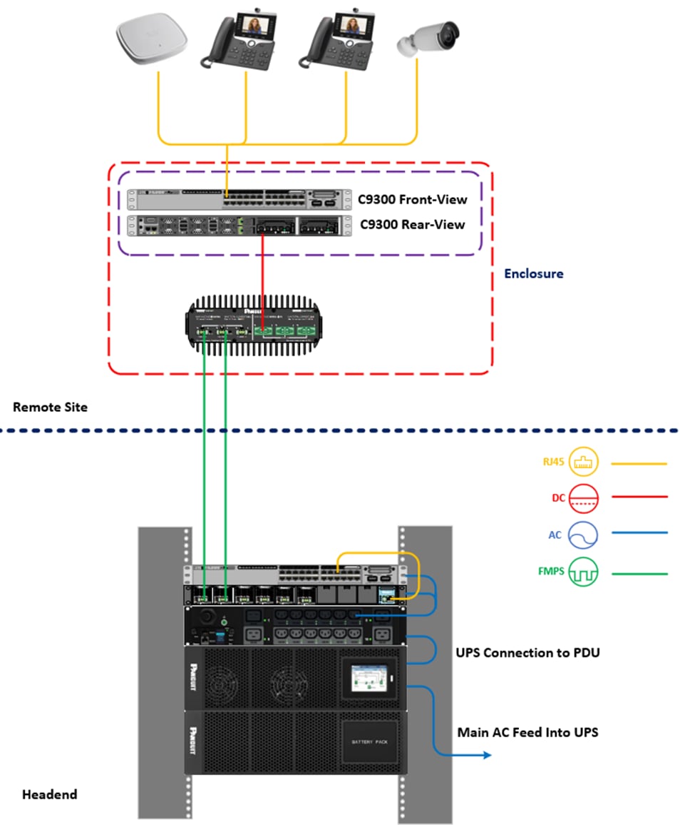
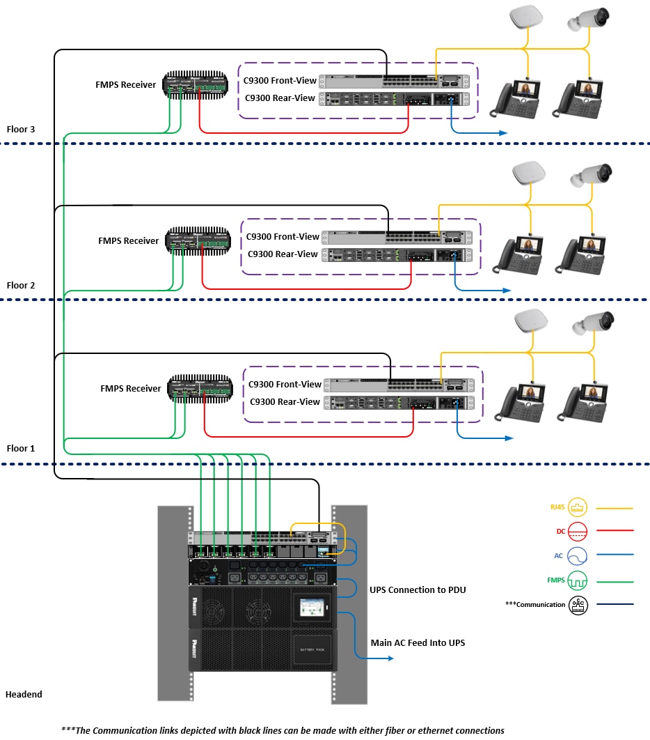
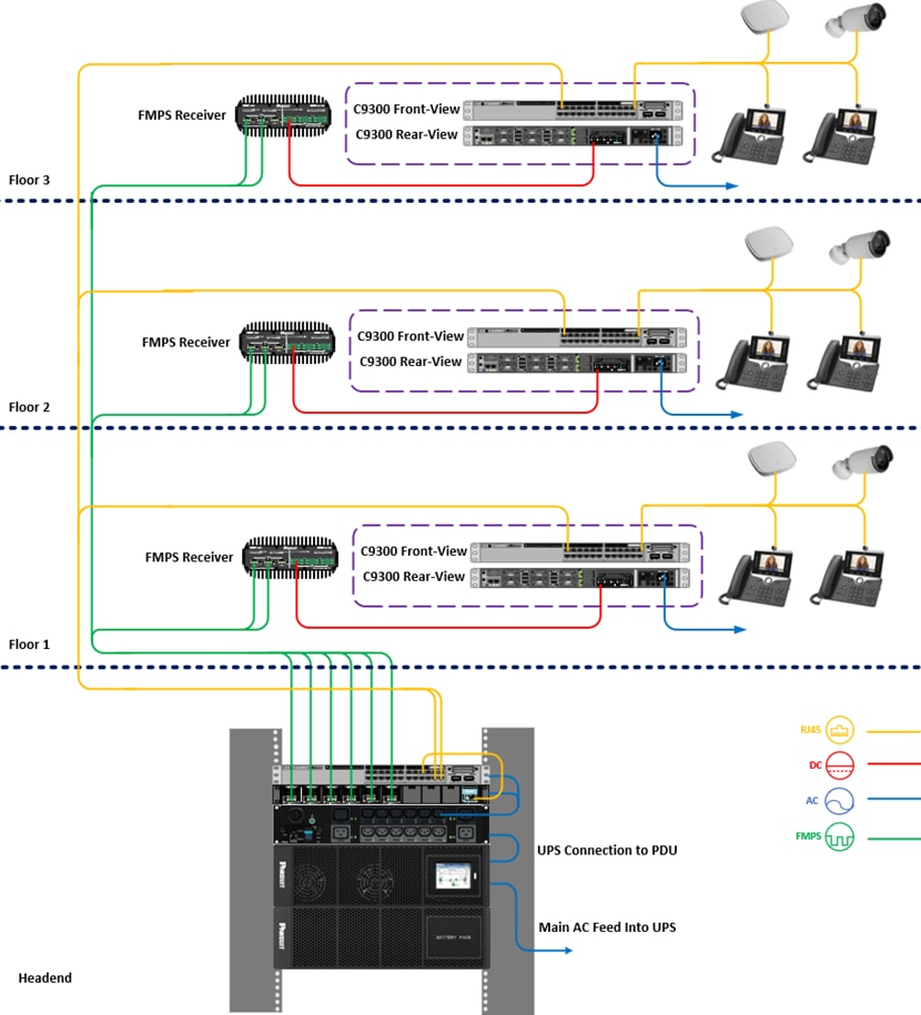
A recommended practice by Panduit for FMPS is to centralize the power delivery architecture to as few physical locations and square footage throughout a floor. FMPS enables this recommendation by permitting devices to be deployed at remote sites a considerable distance away. The remote sites will then converge to the FMPS in the center of the deployment.
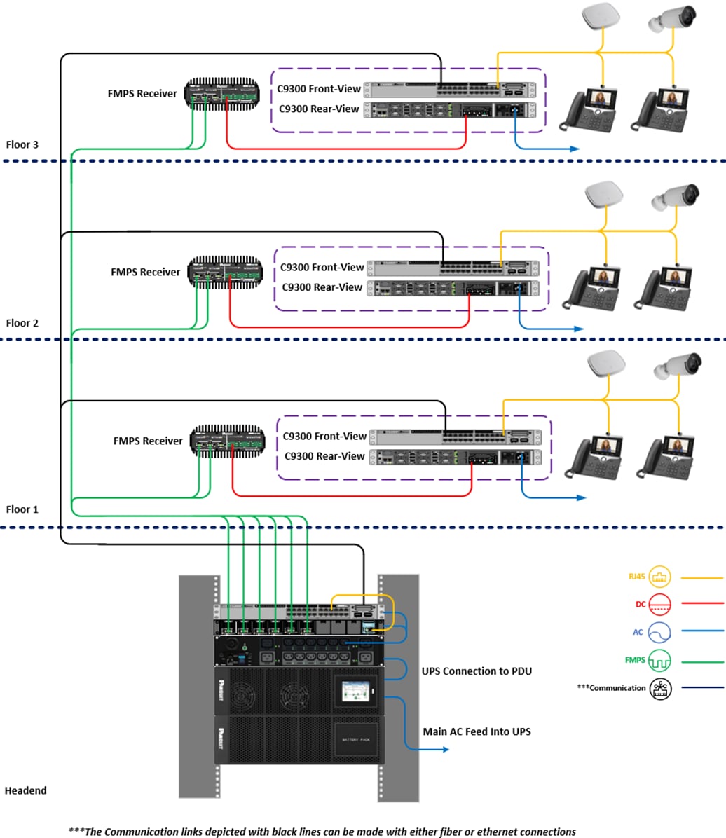
In the example above, the FMPS, AC power source, uninterruptible power supply, to be called UPS henceforth, and necessary environmental controls can all be located on the main floor in the headend/main distribution frame, and the DC power from the FMPS can be distributed to provide the required power as necessary. This reduces the need for solutions infrastructure such as wall outlets, power distribution units, and other high-voltage delivery solutions to be implemented in remote locations.
Instead, enclosures containing the FMPS Receiver and PoE switch to power the access points can be installed on each floor, and the requisite connections:
● multiconductor connections from Transmitters in headend/main distribution frame to Receivers in enclosures
● ethernet connections from PoE switches to access points can then be made to provide wireless network connectivity to the building depicted above.
The use case can be deployed to power a multitude of PoE endpoints such as access points, cameras, phones, digital signage, and any endpoint that is powered through an ethernet connection back to the PoE switch. This permits for flexible deployments as opposed to traditional high-voltage AC circuits since endpoint deployment would be dictated by location of power delivery such as power outlets along a wall, junction boxes, and other mechanisms.
By having components such as the circuit breakers, transformers, UPS, FMPS chassis, power supply, and Transmitters in one centralized location, a centralized architecture will reduce the complexity of installation, maintenance and monitoring the power system.
Traditional power methods offer no monitoring or control capabilities of the electrical circuits. The Class 4 FMPS offers granular monitoring and control capabilities to all edge points from a single, centralized location. Users improve operational efficiency with the ability to troubleshoot and power cycle switches remotely without having to send a technician on-site. The monitoring capabilities of the Class 4 FMPS give users a view of available power capacity at each remote location simplifying future moves/adds/changes.
The modularity of Panduit FMPS allows the solution to be tailored to meet the immediate power delivery requirements, while allowing the solution to grow to meet the power demands of the future. FMPS is designed with Hot-Swappable components that make it easy to make move/add/change for a more flexible and scalable power infrastructure, unlike fixed local power.
As evidenced by the test case in this document, the requirement to power a single 715-watt DC power supply on a Cisco Catalyst C9300-24H can be met with the following configuration of FMPS:
● 1 chassis
● 1 power supply
● 2 Transmitters
● 1 Receiver
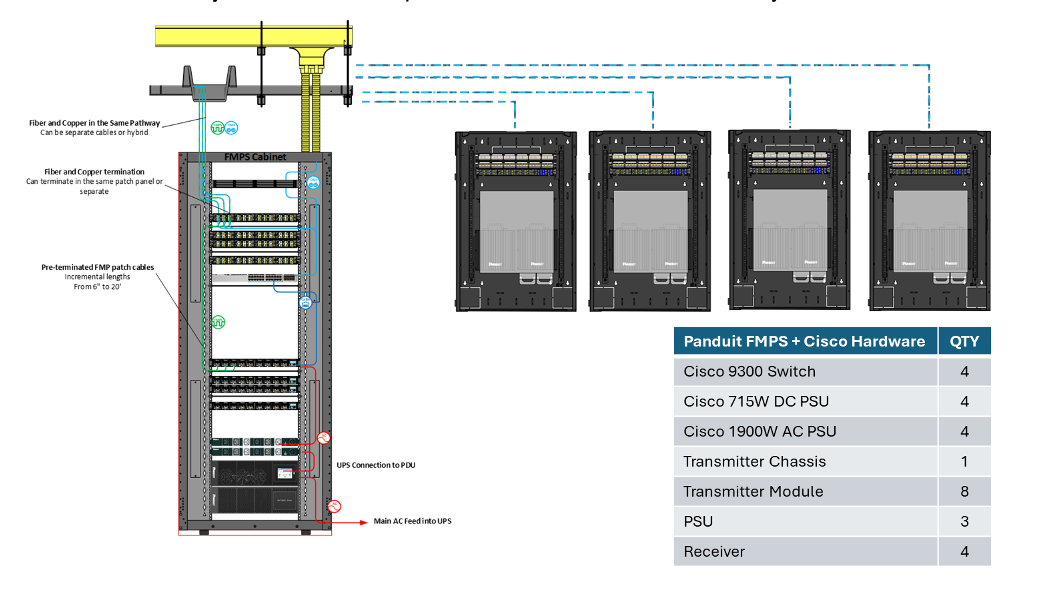
If the chassis were to be populated with the modules in the following configuration:
● 1 chassis
● 3 power supplies
● 8 Transmitters
● 4 Receivers
The system above, using 16-AWG cables to connect the Transmitters to Receivers, could power 4 C9300 switches each powered by a single 715-watt DC power supply up to 1000 meters away, as illustrated below.
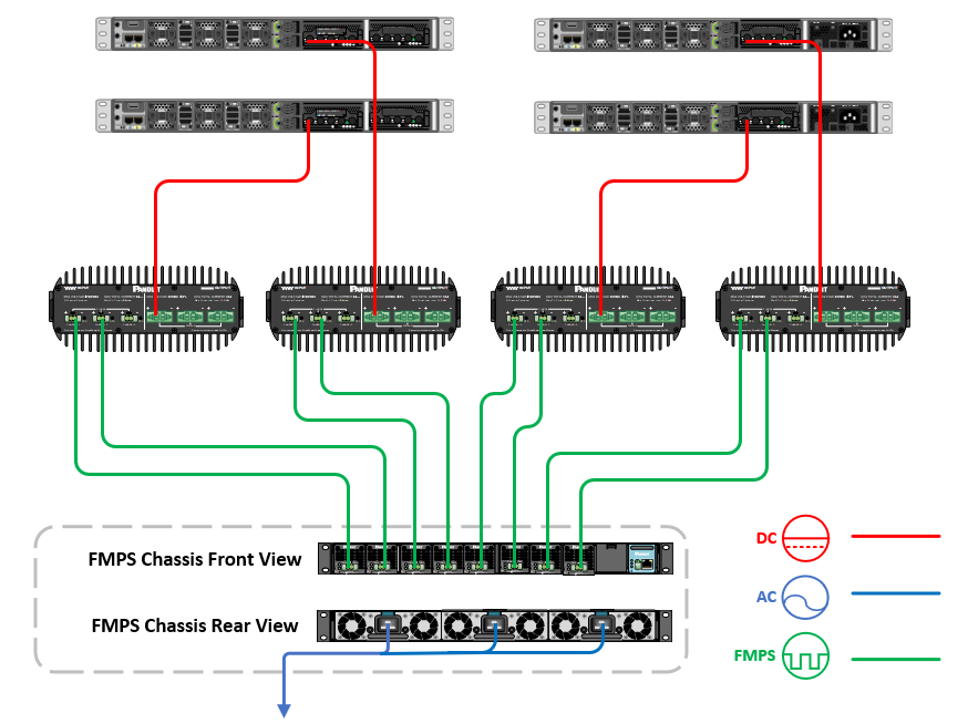
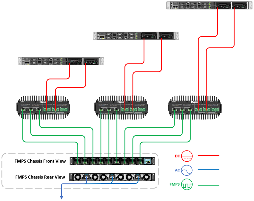
If the chassis were to be populated with the modules in the following configuration:
● 1 chassis
● 3 power supplies
● 9 Transmitters
● 3 Receivers
The system above, using 16-AWG cables to connect the Transmitters to Receivers, could power 3 C9300 switches each powered by two 715-watt DC power supply up to 450 meters away, as illustrated below.
Leveraging its modularity, FMPS can be scaled down or up to meet the current needs of a solution while permitting growth in the future.
Test Case with Cisco Catalyst 9300
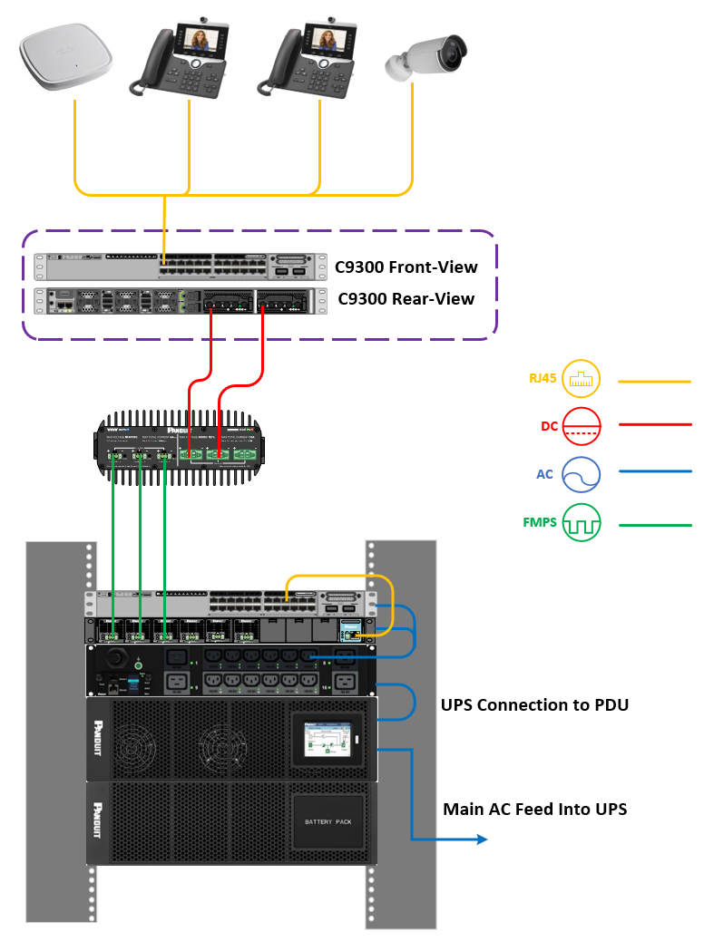
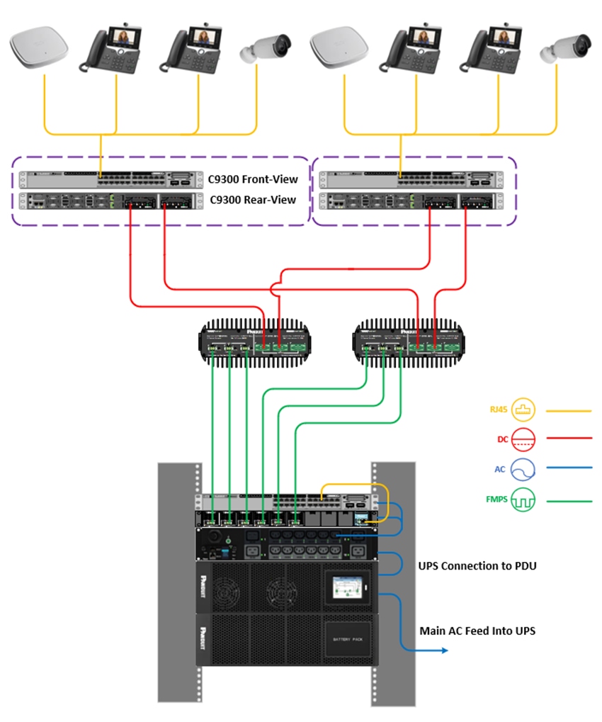
To demonstrate the capabilities of the FMPS, a PoE solution was deployed where the FMPS acted as both the primary method of power delivery as well as a backup to a Cisco Catalyst 9300 switch, C9300-24H. This switch The C9300 can deliver up to 90 watts to a PoE device from each interface, so certain tests were conducted with PoE endpoints drawing as low as 15 watts on each interface to as high as 90 watts on each interface. The diagram for the architecture of the deployment is below.
The FMPS will be connected to the AC power source to deliver the power to the C9300.
The C9300 will receive both DC power from the FMPS Receivers as well as traditional high-voltage AC power to power on PoE endpoints. For this test, the switch will be running software version Cisco IOS XE Dublin 17.12.3, which at the time of writing this document is the Cisco suggested release for this specific model, the Catalyst C9300-24H.
The release notes for the software can be found at:
The PoE endpoints will serve to act as a point of validation to confirm that the C9300 is successfully receiving power from the FMPS to turn them on.
The Panduit Class 4 3-pair 16 AWG, to be called multiconductor cable henceforth, will connect the Transmitter modules to the Receivers to deliver the pulse current.
The variables that will change for individual test cases are outlined below.
The FMPS will be deployed in the PoE solution with a variety of configurations, where the number of power supplies, Transmitter modules, and Receivers will be adjusted to deliver the necessary power to the C9300.
The distance of the multiconductor cable will vary between 1000 meters and 450 meters to meet the requirements to power the C9300. As we will demonstrate, In some test cases, the current delivered across 1000 meters will suffice to power the C9300, while in others, the current will not be sufficient, so the distance will have to be reduced to 450 meters. The calculated wattage across distance relative to the number of cable pairs and gauge of said cables can be found in the graphs below.
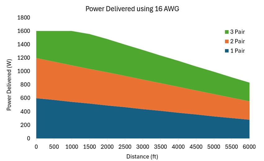
Wattage Delivered Relative to Distance Using 16 AWG Multiconductor Cable and Pair Count
| Distance (ft) |
Wattage 3-Pair |
Wattage 2-Pair |
Wattage 1-Pair |
| 500 |
1600 |
1150 |
575 |
| 1000 |
1600 |
1100 |
550 |
| 1500 |
1530 |
1050 |
525 |
| 2000 |
1460 |
1000 |
500 |
| 2500 |
1390 |
950 |
475 |
| 3000 |
1320 |
900 |
450 |
| 3500 |
1250 |
850 |
425 |
| 4000 |
1180 |
800 |
400 |
| 4500 |
1110 |
750 |
375 |
| 5000 |
1040 |
700 |
350 |
| 5500 |
970 |
650 |
325 |
| 6000 |
900 |
600 |
300 |
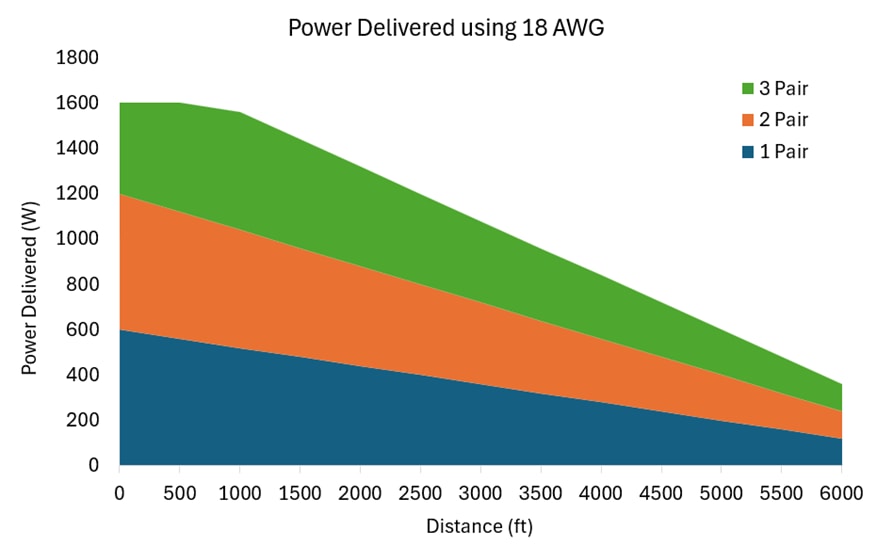
Wattage Delivered Relative to Distance Using 18 AWG Multiconductor Cable and Pair Count
| Distance (ft) |
Wattage 3-Pair |
Wattage 2-Pair |
Wattage 1-Pair |
| 500 |
1600 |
1100 |
550 |
| 1000 |
1491 |
1024 |
512 |
| 1500 |
1382 |
948 |
474 |
Catalyst 9300 Power Supply Configurations
A variety of power supply configurations for the C9300 will be tested to ensure that the desired outcomes are achieved to validate certain use cases. The quantity of AC and DC power supplies mounted will be varied to test features such as power redundancy and port priority. The configurations are as follows:
1. One 715 W DC power supply
2. One 715 W DC power supply and one 1900 W AC power supply
3. Two 715 W DC power supplies
In the third configuration, a single homing and dual homing configuration will be tested, where in the single homing, each power supply will be connected to its own dedicated Receiver, and the dual homing architecture, consisting of two Receivers and two C9300’s, will have two Receivers powering one DC power supply on each C9300 for complete redundancy.
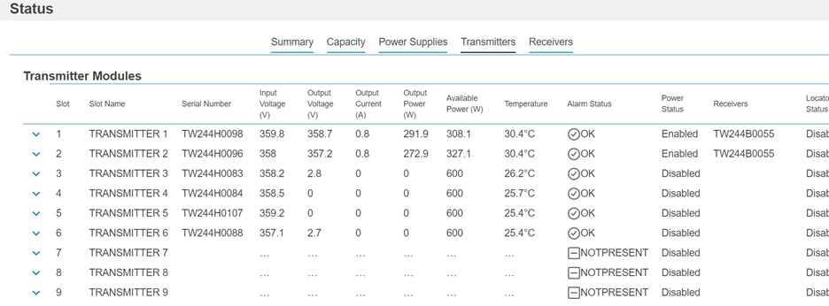
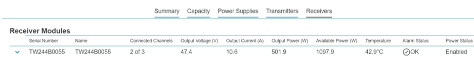
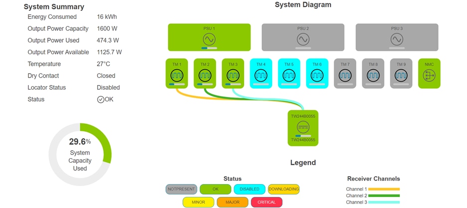
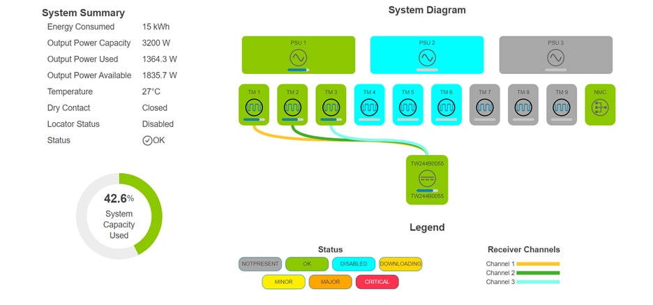
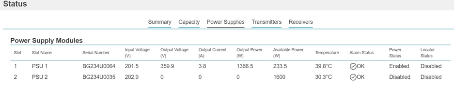
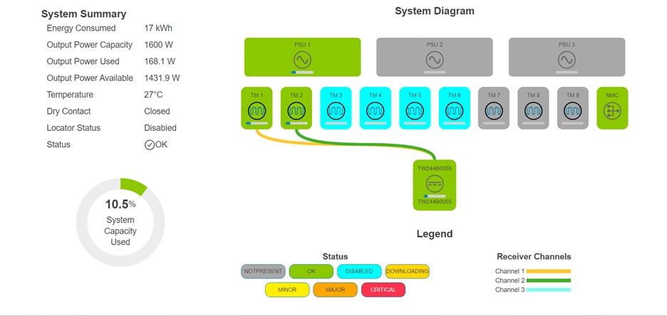
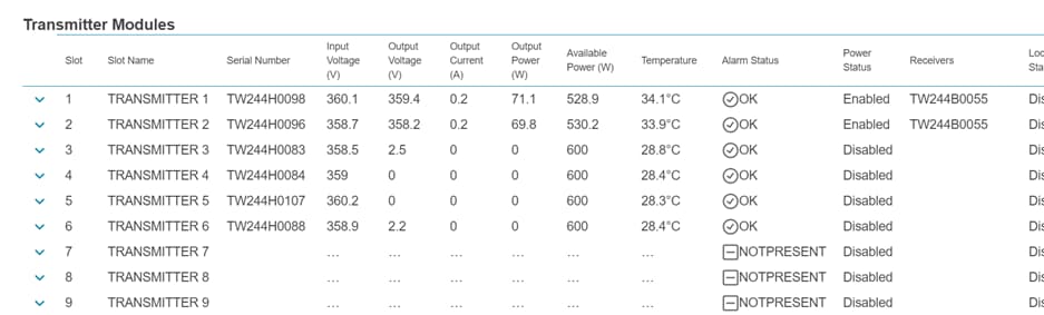
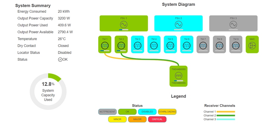
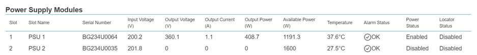
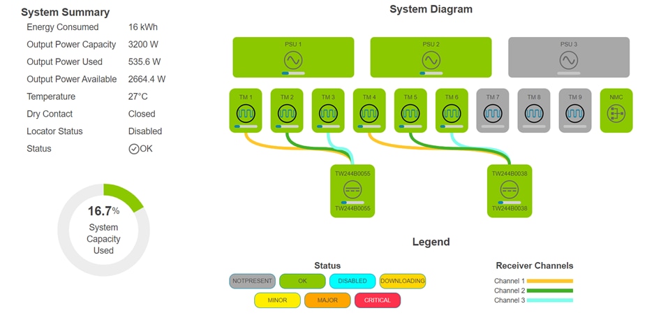
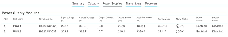
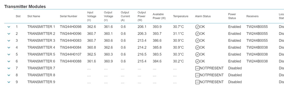
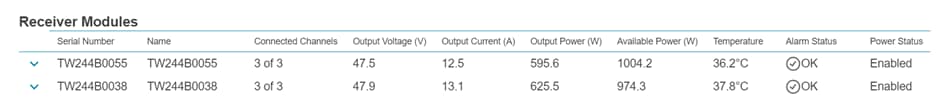
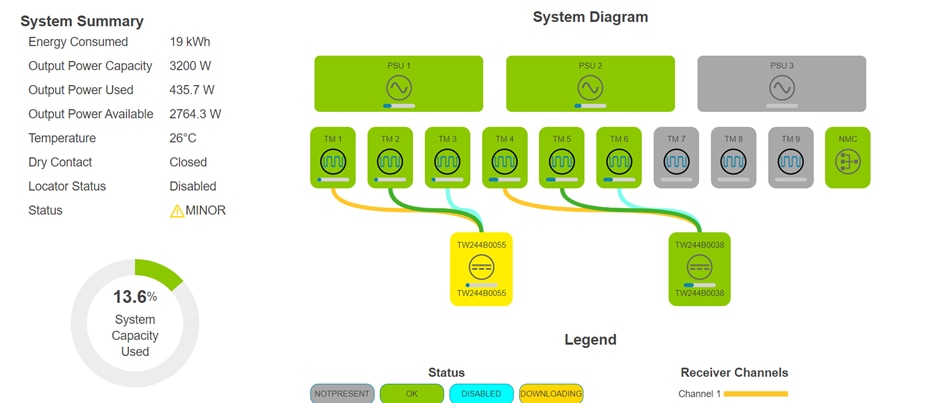
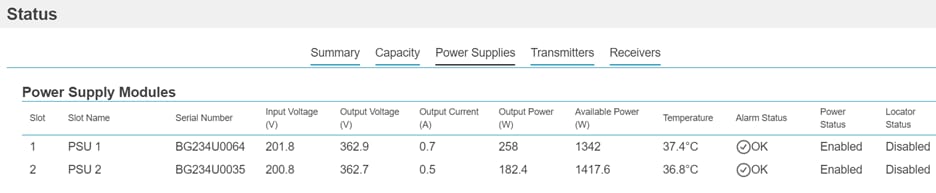
To validate that the FMPS is operating as intended, the management graphical user interface will be referenced to check for conditions of all the components of the FMPS.
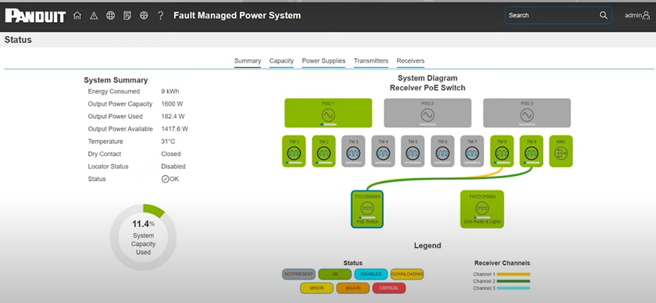
Leveraging the interface will allow the FMPS to be monitored to ensure that the system is receiving the power from the source as well as delivering the requisite amount to power on the C9300.
Operation of Cisco Catalyst 9300
The C9300 command line interface will also be used to validate the FMPS as a viable source of power. There are several commands where the outputs will be able to verify the switch is receiving enough power to run its own systems as well as deliver power to the connected PoE endpoints.
The following commands, which will be executed with in EXEC mode with elevated privileges, will reveal the operational parameters on the switch:
show environment all
show power detail
show power inline upoe-plus
For the sake of simplicity and readability, the outputs of some commands will be shown as tables with parameters of interest and not raw text outputs in the results section of the test cases. The parameters of interest have been made into bold and italics for easier viewing, and to provide an opportunity for administrators to locate the said values from the sample outputs above.
The “show environment all” command displays the fan, temperature, and power information of the internal power supplies connected to the switch. A sample of the output of the command is shown below:
Sensor List: Environmental Monitoring
Sensor Location State Reading Range(min-max)
PS1 Vout 1 GOOD 56238 mV na
PS1 Vin 1 GOOD 48063 mV 90 - 264
PS1 CURin 1 GOOD 8250 mA na
PS1 Curout 1 GOOD 6453 mA na
PS1 POWin 1 GOOD 397000 mW na
PS1 POWout 1 GOOD 362500 mW na
PS1 FAN 1 GOOD 6736 rpm na
PS2 Vout 1 FAULTY 0 mV na
PS2 Vin 1 FAULTY 0 mV 90 - 264
PS2 CURin 1 FAULTY 0 mA na
PS2 CURout 1 FAULTY 0 mA na
PS2 POWin 1 FAULTY 0 mW na
PS2 POWout 1 FAULTY 0 mW na
PS2 FAN 1 FAULTY 0 rpm na
SYSTEM INLET 1 GREEN 25 Celsius 0 - 56
SYSTEM OUTLET 1 GREEN 34 Celsius 0 - 125
SYSTEM HOTSPOT 1 GREEN 51 Celsius 0 - 125
Switch FAN Speed State Airflow direction
---------------------------------------------------
1 1 5440 OK Front to Back
1 2 5440 OK Front to Back
1 3 5440 OK Front to Back
SW PID Serial# Status Sys Pwr PoE Pwr Watts
-- ------------------ ---------- --------------- ------- ------- -----
1A PWR-C1-715WDC DCC2316E1GU OK Good Good 715
1B Unknown Unknown No Input Power Bad Bad Unknown
---------------------------------------------------
The “show power detail” command will display the cumulative power allocation information on a 9300 in detail. The values of particular interest are instantaneous power used, and the power summary which have been highlighted in the sample to follow. The instantaneous power shows the real-time value of the wattage being consumed to keep the switch in an operational state, while the power summary table shows the allocated wattage, and not the consumed wattage.
A sample of the output of the command is shown below:
SW PID Serial# Status Sys Pwr PoE Pwr Watts
-- ------------------ ---------- --------------- ------- ------- -----
1A PWR-C1-715WDC DCC2316E1GU OK Good Good 715
1B Unknown Unknown No Input Power Bad Bad Unknown
PS Configuration Mode : SP-PS
PS Operating state : Stndaln
Power supplies currently active : 1
Power supplies currently available : 2
Automatic Module Shutdown : Enabled
Power Budget Mode = SP-PS
shutdown Power Out of In
Mod Model No Priority State Budget Instantaneous Peak Reset Reset
--- -------------------- -------- -------- ------ ------------- ---- ------ -----
1 C9300-24H 4 accepted 240 70 99 240 50
--- -------------------- -------- -------- ------ ------------- ---- ------ -----
Total 240
Power Summary Maximum
(in Watts) Used Available
------------- ------ ---------
System Power 240 240
POE Power 323 475
------------- ------ ---------
Total 563 715
The “show power inline upoe-plus” command will display the detailed PoE status of the entire switch. A sample of the output of the command is shown below:
Module Available Used Remaining
(Watts) (Watts) (Watts)
------ --------- -------- ---------
1 475.0 323.4 151.6
Device IEEE Mode - BT
Codes: DS - Dual Signature device, SS - Single Signature device
SP - Single Pairset device
Interface Admin Type Oper-State Power(Watts) Class Device Name
State Alt-A,B Allocated Utilized Alt-A,B
----------- ------ ---- ------------- --------- --------- ------- -----------
Gi1/0/1 auto SS on,off 15.4 14.1 3 Ieee PD
Gi1/0/2 auto SS on,off 15.4 14.1 3 Ieee PD
Gi1/0/3 auto SS on,off 15.4 14.3 3 Ieee PD
Gi1/0/4 auto SS on,off 15.4 14.2 3 Ieee PD
Gi1/0/5 auto SS on,off 15.4 14.1 3 Ieee PD
Gi1/0/6 auto SS on,off 15.4 14.0 3 Ieee PD
Gi1/0/7 auto SS on,off 15.4 14.1 3 Ieee PD
Gi1/0/8 auto SS on,off 15.4 13.9 3 Ieee PD
Gi1/0/9 auto SS on,off 15.4 13.9 3 Ieee PD
Gi1/0/10 auto SS on,off 15.4 14.1 3 Ieee PD
Gi1/0/11 auto SS on,off 15.4 14.1 3 Ieee PD
Gi1/0/12 auto SS on,off 15.4 14.0 3 Ieee PD
Gi1/0/13 auto SS on,off 15.4 13.9 3 Ieee PD
Gi1/0/14 auto SS on,off 15.4 13.9 3 Ieee PD
Gi1/0/15 auto SS on,off 15.4 13.9 3 Ieee PD
Gi1/0/16 auto SS on,off 15.4 14.0 3 Ieee PD
Gi1/0/17 auto SS on,off 15.4 13.9 3 Ieee PD
Gi1/0/18 auto SS on,off 15.4 13.9 3 Ieee PD
Gi1/0/19 auto SS on,off 15.4 14.1 3 Ieee PD
Gi1/0/20 auto SS on,off 15.4 13.9 3 Ieee PD
Gi1/0/21 auto SS on,off 15.4 14.1 3 Ieee PD
Gi1/0/22 auto n/a off 0.0 0.0 n/a
Gi1/0/23 auto n/a off 0.0 0.0 n/a
Gi1/0/24 auto n/a off 0.0 0.0 n/a
--------- ------ ---------- ---------- ---------- ------------------- -----
Totals: 21 on 323.4 294.7
Additional information regarding the commands for software version 17.12.3 can be found at:
During testing, some notable observations were made:
4. Power inline port priority high command only works when total load of endpoints connected to them do not exceed the total capacity of operational power supply
a. If a power supply is rated for 715 watts and 240 is budgeted for system operations, the load on the interfaces configured with high port priority should not exceed the remaining 475
5. Hardware versions of the power supply must match to ensure proper function and operations. The versions of the power supply can only be found by looking at the label on the power supply. Running “show environment all” on the switch will provide the product identification, but not the version.
a. Using mismatching versions have led to issues and power resilience not working:
i. switch reloading when one power supply loses power
ii. current overdraw and extreme fan operation in response to heat
b. For these tests, two pairs of 715-watt power supplies were used:
i. PIDVID: PWR-C1-715WDC V00
ii. PIDVID: PWR-C1-715WDC V01
c. When the version of the hardware had a mismatch, the switches did not operate as intended, but when the tests were conducted with matching hardware versions, the switches operated as intended.
Design Architectures And Tests Outcome
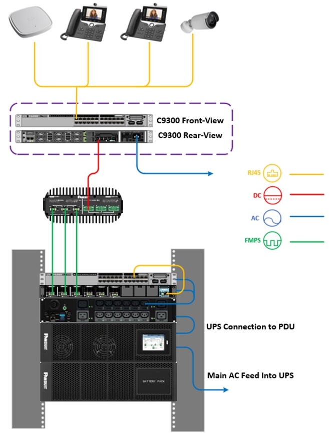
Distributed Network Architecture With Centralized Power
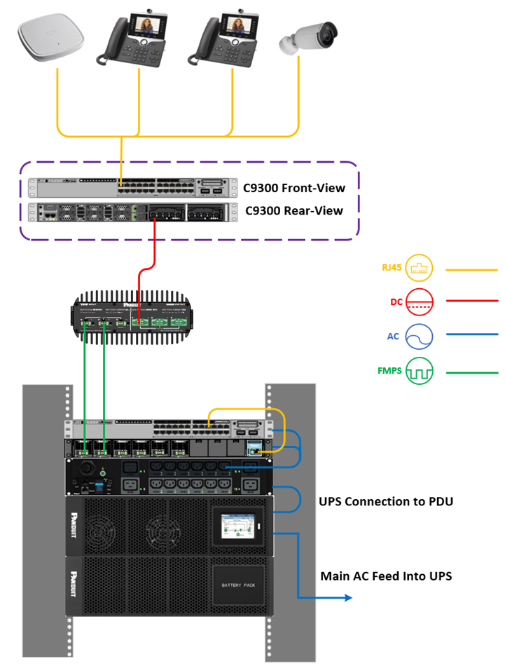
This architectural design enables the placement of switches closer to PoE loads, eliminating the need for a nearby power source. Switches can be installed virtually anywhere with minimal requirements for space or power. This approach significantly reduces the length of Ethernet cabling needed to connect switches to endpoints, while also allowing for future expansion of PoE devices. The two test cases presented follow this architecture and represent two different options for power and distance at the switch.
A sample diagram of the architecture is shown below.
Test 1: FMPS to Single DC Power Supply on 9300
For Test 1, the FMPS will provide DC power from a single Receiver to a single DC power supply on the C9300. This is a basic test being conducted to validate FMPS can deliver sufficient power to turn on the switch as well as the PoE endpoints connected to it.
The desired outcome for the test is:
● C9300 to successfully provide power to 21 PoE end devices drawing 15 watts
● C9300 to successfully provide power to 4 PoE end devices drawing 90 watts
An example where such a design would be implemented is an environment where PoE devices need to be powered a considerable distance away from a power source, beyond the 100 meters that the 802.3bt standards outline.
Using FMPS, a PoE switch can be deployed, 1000 meters tested in this case, remotely from the power source, and from the switch, so long as it is capable of meeting 802.3bt standards, the PoE endpoint to be powered can be installed another 100 meters away.
Of the 715 watts delivered to the switch, 240 will be allocated for switch operations. Therefore, this test seeks to validate that the switch is capable of 475W of PoE load and the PoE endpoints can be powered from 1100 meters away from the FMPS chassis.
|
|
|
| FMPS Chassis Quantity |
1 |
| FMPS Power Supply Quantity |
1 |
| FMPS Transmitter Quantity |
2 |
| FMPS Receiver Quantity |
1 |
| Multiconductor Cable Length |
1000 m |
| Multiconductor Cable Gauge |
16 AWG |
| C9300 Power Supply Type |
DC |
| C9300 Power Supply Quantity |
1 |
| Homing Architecture |
N/A |
Bill of Materials Panduit
| Item Name |
PID |
Quantity |
| FMPS Chassis |
PXTC1ARA |
1 |
| FMPS Power Supply Unit |
PXU1AJANNNXX |
1 |
| FMPS Transmitter |
PXTM1AF |
2 |
| FMPS Receiver |
PXR1AJD |
1 |
| Class 4 Copper Cable |
PXUP316ARD-UQ |
1000 m |
Bill of Materials Cisco
| Item Name |
PID |
Quantity |
| Catalyst 9300-24H |
C9300-24H-E |
1 |
| 715 Watt DC Power Supply Unit |
PWR-C1-715WDC= |
1 |
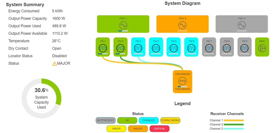
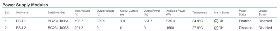
FMPS Management Interface Screenshots for Powering 15-Watt Endpoints
FMPS Management Interface Screenshots for Powering 90-Watt Endpoints
Catalyst 9300 Show Command Outputs for Powering 15 Watts
show environment all
| Parameter |
State |
Reading |
| PS1 Vout |
GOOD |
56238 mV |
| PS1 Vin |
GOOD |
48063 mV |
| PS1 CURin |
GOOD |
8250 mA |
| PS1 CURout |
GOOD |
6453 mA |
| PS1 POWin |
GOOD |
397000 mW |
| PS1 POWout |
GOOD |
362500 mW |
| PS1 FAN |
GOOD |
6736 rpm |
| PS2 Vout |
FAULTY |
0 mV |
| PS2 Vin |
FAULTY |
0 mV |
| PS2 CURin |
FAULTY |
0 mA |
| PS2 CURout |
FAULTY |
0 mA |
| PS2 POWin |
FAULTY |
0 mW |
| PS2 POWout |
FAULTY |
0 mW |
| PS2 FAN |
FAULTY |
0 rpm |
The second power supply on the switch is in the “FAULTY” state since there is no power supply populating the second bay on the switch.
show power detail
Power Supply Status
| Power Supply ID |
Status |
System Power |
PoE Power |
| A |
OK |
Good |
715 |
| B |
Unknown |
Bad |
Unknown |
System Power Status
| Module |
State |
Budget |
Instantaneous |
| 1 |
accepted |
240 |
70 |
Power Summary
| Power Type |
Used |
Available |
| System Power |
240 |
240 |
| PoE Power |
323 |
475 |
| Total Power |
563 |
715 |
show power inline upoe-plus
| Interface |
Allocated Power |
Utilized |
| Gi 1/0/1 |
15.4 |
14.1 |
| Gi 1/0/2 |
15.4 |
14.1 |
| Gi 1/0/3 |
15.4 |
14.3 |
| Gi 1/0/4 |
15.4 |
14.2 |
| Gi 1/0/5 |
15.4 |
14.1 |
| Gi 1/0/6 |
15.4 |
14 |
| Gi 1/0/7 |
15.4 |
14.1 |
| Gi 1/0/8 |
15.4 |
13.9 |
| Gi 1/0/9 |
15.4 |
13.9 |
| Gi 1/0/10 |
15.4 |
14.1 |
| Gi 1/0/11 |
15.4 |
14.1 |
| Gi 1/0/12 |
15.4 |
14 |
| Gi 1/0/13 |
15.4 |
13.9 |
| Gi 1/0/14 |
15.4 |
13.9 |
| Gi 1/0/15 |
15.4 |
13.9 |
| Gi 1/0/16 |
15.4 |
14 |
| Gi 1/0/17 |
15.4 |
13.9 |
| Gi 1/0/18 |
15.4 |
13.9 |
| Gi 1/0/19 |
15.4 |
14.1 |
| Gi 1/0/20 |
15.4 |
13.9 |
| Gi 1/0/21 |
15.4 |
14.1 |
Catalyst 9300 Show Command Outputs for Powering 90 Watts
show environment all
| Parameter |
State |
Reading |
| PS1 Vout |
GOOD |
56238 mV |
| PS1 Vin |
GOOD |
48063 mV |
| PS1 CURin |
GOOD |
10313 mA |
| PS1 CURout |
GOOD |
8141 mA |
| PS1 POWin |
GOOD |
495000 mW |
| PS1 POWout |
GOOD |
459000 mW |
| PS1 FAN |
GOOD |
6736 rpm |
| PS2 Vout |
FAULTY |
0 mV |
| PS2 Vin |
FAULTY |
0 mV |
| PS2 CURin |
FAULTY |
0 mA |
| PS2 CURout |
FAULTY |
0 mA |
| PS2 POWin |
FAULTY |
0 mW |
| PS2 POWout |
FAULTY |
0 mW |
| PS2 FAN |
FAULTY |
0 rpm |
The second power supply on the switch is in the “FAULTY” state since there is no power supply populating the second bay on the switch.
show power detail
Power Supply Status
| Power Supply ID |
Status |
System Power |
PoE Power |
Watts |
| A |
OK |
Good |
Good |
715 |
| B |
Unknown |
Bad |
Bad |
Unknown |
System Power Status
| Module |
State |
Budget |
Instantaneous |
| 1 |
accepted |
240 |
67 |
Power Summary
| Power Type |
Used |
Available |
| System Power |
240 |
240 |
| PoE Power |
450 |
475 |
| Total Power |
690 |
715 |
show power inline upoe-plus
| Interface |
Allocated Power |
Utilized Power |
| Gi 1/0/1 |
90 |
77.3 |
| Gi 1/0/2 |
90 |
77.7 |
| Gi 1/0/3 |
90 |
77.7 |
| Gi 1/0/4 |
90 |
77.5 |
| Gi 1/0/5 |
90 |
77.4 |
The remaining interfaces were in a power-deny state due to insufficient PoE power.
Test 1 was successful and validates FMPS will provide the requisite 715 watts across 1000 meters to the switch with the following parameters of the FMPS:
● 1 FMPS power supply, has capacity to provide 1600 watts, exceeding the required 715 watts
● 2 Transmitters, each Transmitter can only provide 600 watts, so requires two
● 1 Receiver, each Receiver has three input channels that can receive power from the Transmitters, only one required to receive input from two Transmitters
● 1000 meters of 16 AWG multiconductor cable
The FMPS management console shows that the Transmitters delivered 1600 watts to the Receiver, and the “show power detail” output shows that the switch received all 715 watts from the Receiver.
A single FMPS Transmitter can support four distributed 9300 switches up to 1000 meters away from a centralized point. For more details, see the topic Scalability.
Test 2: FMPS to Dual DC Power Supplies on C9300
For Test 2, the FMPS will provide DC power from a single Receiver to two DC power supplies on the 9300 for basic functionality.
The desired outcome for the test is:
● C9300 to successfully provide power to 21 PoE end devices drawing 15 watts
● C9300 to successfully provide power to 13 PoE end devices drawing 90 watts
◦ Outcomes from test 1 are expected to carry over, but with the addition of PoE wattage available from the second power supply.
An example where such a design would be implemented in such a fashion is where 715 watts from a single power supply on the C9300 is insufficient, and requires additional wattage from the second 715 watt power supply.
Using FMPS, a PoE switch can be deployed, 450 meters tested in this case, remotely from the power source, and from the switch, so long as it is capable of meeting 802.3bt standards, the PoE endpoint to be powered can be another installed another 100 meters away. The switch will receive 1430 watts in total from the Receiver, but 240 will be allocated for switch operations. Therefore this test seeks to validate that the switch is capable of 1190W of PoE load and the PoE endpoint can be powered from 550 meters away from the FMPS chassis.
|
|
|
| FMPS Chassis Quantity |
1 |
| FMPS Power Supply Quantity |
1 |
| FMPS Transmitter Quantity |
3 |
| FMPS Receivers |
1 |
| Multiconductor Cable Length |
450 m |
| Multiconductor Cable Gauge |
16 AWG |
| C9300 Power Supply Type |
DC |
| C9300 Power Supply Quantity |
2 |
| Homing Architecture |
single |
Bill of Materials Panduit
| Item Name |
PID |
Quantity |
| FMPS Chassis |
PXTC1ARA |
1 |
| FMPS Power Supply Unit |
PXU1AJANNNXX |
1 |
| FMPS Transmitter |
PXTM1AF |
3 |
| FMPS Receiver |
PXR1AJD |
1 |
| Class 4 Copper Cable |
PXUP316ARD-UQ |
450 m |
Bill of Materials Cisco
| Item Name |
PID |
Quantity |
| Catalyst 9300-24H |
C9300-24H-E |
1 |
| 715 Watt DC Power Supply Unit |
PWR-C1-715WDC= |
2 |
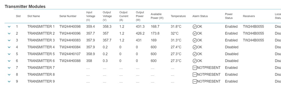
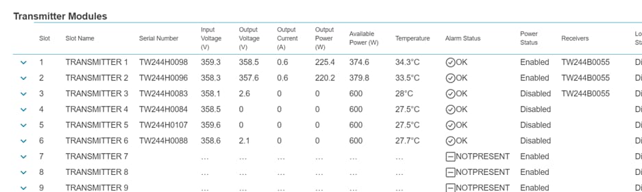
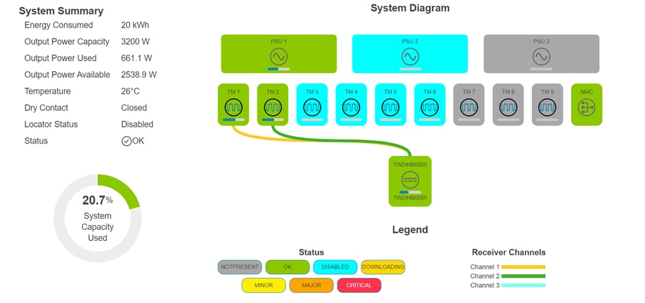
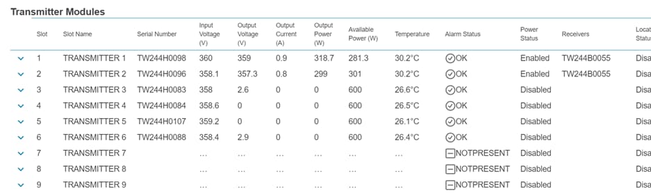
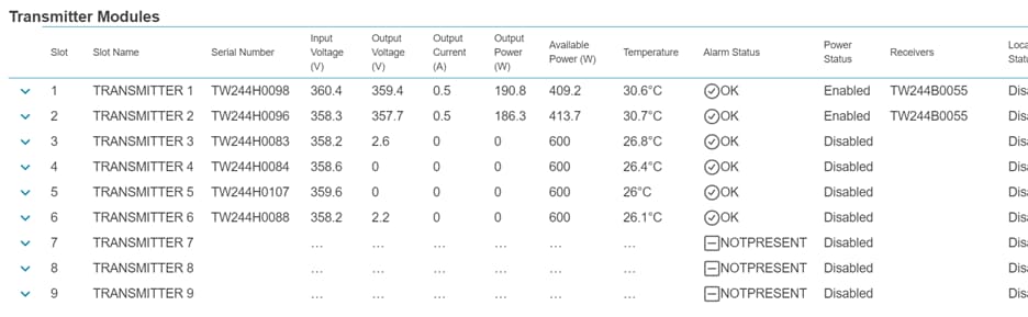
FMPS Management Interface Screenshots for Powering 15 Watt Endpoints
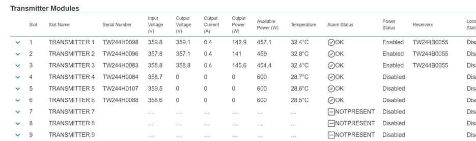
FMPS Management Interface Screenshots for Powering 90 Watt Endpoints
Catalyst 9300 Show Command Outputs for Powering 15 Watts
show environment all
| Parameter |
State |
Reading |
| PS1 Vout |
GOOD |
56174 mV |
| PS1 Vin |
GOOD |
48375 mV |
| PS1 CURin |
GOOD |
3992 mA |
| PS1 CURout |
GOOD |
3063 mA |
| PS1 POWin |
GOOD |
193500 mW |
| PS1 POWout |
GOOD |
170250 mW |
| PS1 FAN |
GOOD |
6800 rpm |
| PS2 Vout |
GOOD |
56174 mV |
| PS2 Vin |
GOOD |
48125 mV |
| PS2 CURin |
GOOD |
4477 mA |
| PS2 CURout |
GOOD |
3438 mA |
| PS2 POWin |
GOOD |
215250 mW |
| PS2 POWout |
GOOD |
192000 mW |
| PS2 FAN |
GOOD |
5488 rpm |
show power detail
Power Supply Status
| Power Supply ID |
Status |
System Power |
PoE Power |
Watts |
| A |
OK |
Good |
Good |
715 |
| B |
OK |
Good |
Good |
715 |
System Power Status
| Module |
State |
Budget |
Instantaneous |
| 1 |
accepted |
240 |
76 |
Power Summary
| Power Type |
Used |
Available |
| System Power |
240 |
240 |
| PoE Power |
323 |
1190 |
| Total Power |
563 |
1430 |
show power inline upoe-plus
| Interface |
Allocated Power |
Utilized Power |
| Gi 1/0/1 |
15.4 |
14.0 |
| Gi 1/0/2 |
15.4 |
14.0 |
| Gi 1/0/3 |
15.4 |
14.2 |
| Gi 1/0/4 |
15.4 |
14.2 |
| Gi 1/0/5 |
15.4 |
14.0 |
| Gi 1/0/6 |
15.4 |
14.0 |
| Gi 1/0/7 |
15.4 |
13.1 |
| Gi 1/0/8 |
15.4 |
12.9 |
| Gi 1/0/9 |
15.4 |
13.0 |
| Gi 1/0/10 |
15.4 |
13.1 |
| Gi 1/0/11 |
15.4 |
13.1 |
| Gi 1/0/12 |
15.4 |
13.0 |
| Gi 1/0/13 |
15.4 |
13.9 |
| Gi 1/0/14 |
15.4 |
13.9 |
| Gi 1/0/15 |
15.4 |
13.9 |
| Gi 1/0/16 |
15.4 |
14.0 |
| Gi 1/0/17 |
15.4 |
13.9 |
| Gi 1/0/18 |
15.4 |
13.9 |
| Gi 1/0/19 |
15.4 |
14.1 |
| Gi 1/0/20 |
15.4 |
13.9 |
| Gi 1/0/21 |
15.4 |
14.1 |
Catalyst 9300 Show Command Outputs for Powering 90 Watts
show environment all
| Parameter |
State |
Reading |
| PS1 Vout |
GOOD |
56238 mV |
| PS1 Vin |
GOOD |
47500 mV |
| PS1 CURin |
GOOD |
12047 mA |
| PS1 CURout |
GOOD |
9359 mA |
| PS1 POWin |
GOOD |
574000 mW |
| PS1 POWout |
GOOD |
526000 mW |
| PS1 FAN |
GOOD |
8576 rpm |
| PS2 Vout |
GOOD |
56238 mV |
| PS2 Vin |
GOOD |
47250 mV |
| PS2 CURin |
GOOD |
12563 mA |
| PS2 CURout |
GOOD |
9703 mA |
| PS2 POWin |
GOOD |
598000 mW |
| PS2 POWout |
GOOD |
546000 mW |
| PS2 FAN |
GOOD |
5696 rpm |
show power detail
Power Supply Status
| Power Supply ID |
Status |
System Power |
PoE Power |
Watts |
| A |
OK |
Good |
Good |
715 |
| B |
OK |
Good |
Good |
715 |
System Power Status
| Power Supply ID |
Status |
System Power |
PoE Power |
| 1 |
accepted |
240 |
65 |
Power Summary
| Power Type |
Used |
Available |
| System Power |
240 |
240 |
| PoE Power |
1170 |
1190 |
| Total Power |
1410 |
1430 |
show power inline upoe-plus
| Interface |
Allocated Power |
Utilized Power |
| Gi 1/0/1 |
90 |
77.5 |
| Gi 1/0/2 |
90 |
77.8 |
| Gi 1/0/3 |
90 |
77.7 |
| Gi 1/0/4 |
90 |
77.6 |
| Gi 1/0/5 |
90 |
77.3 |
| Gi 1/0/6 |
90 |
77.5 |
| Gi 1/0/7 |
90 |
77.5 |
| Gi 1/0/8 |
90 |
77.3 |
| Gi 1/0/9 |
90 |
77.2 |
| Gi 1/0/10 |
90 |
77.2 |
| Gi 1/0/11 |
90 |
77.2 |
| Gi 1/0/12 |
90 |
77.2 |
| Gi 1/0/13 |
90 |
77.2 |
The remaining interfaces were in a power-deny state due to lack of available power.
Test 2 was successful and confirms FMPS will provide all 1430 watts across 450 meters split between the two power supplies on the C9300 with the following parameters of the FMPS:
● 1 power supply, has capacity to provide 1600 watts, exceeding the required 1430 watts
● 3 Transmitters, each Transmitter can only provide 600 watts, so requires three
● 1 Receiver, each Receiver has three input channels that can receive power from the Transmitters, only one Receiver required to receive input from two Transmitters
● 450 meters of 16 AWG multiconductor cable, distance reduced to minimize power loss
The FMPS management console shows that the Transmitters delivered 1600 watts to the Receiver, and the “show power detail” output shows that the switch received all 1430 watts from the Receiver.
Test 2 conclusively shows that should a solution require more than 715 watts, FMPS can power a second power supply to supplement the first and provide an additional 715 watts to power the endpoints connected the PoE switch.
A single FMPS Transmitter can support three distributed 9300 switches up to 450 meters away from a centralized point. For more details, see the topic Scalability.
Centralized DC Power Back-Up For Power Redundancy
This architectural design is well-suited for both new construction and retrofit projects. By utilizing a centralized UPS for DC power backup, it enhances power reliability, ensuring uninterrupted power delivery to critical PoE loads. Additionally, it improves operational efficiency by reducing maintenance costs associated with managing multiple distributed UPS units.
A sample diagram where FMPS is deployed to a brownfield PoE deployment with a pre-existing AC power connection is shown below.
Test 3: FMPS to DC Power Supply as Backup
For Test 3, the FMPS will provide DC power from a single Receiver to a DC power supply on the C9300, and an AC power supply will be mounted to the other bay on the C9300. The intent of this use case is to demonstrate FMPS’ ability to serve as a backup to the AC power.
To test FMPS as a backup solution to the AC power, the C9300 was turned on with both DC and AC power supplies, and once the switch was in a steady state, power was cut to the AC power supply to observe whether FMPS powered the DC power supply to maintain continuity to the C9300.
In conjunction with the power redundancy, the “power inline port priority high” command was used with the 90-watt endpoints to ensure that in the event of power shedding, the interfaces configured with high priority would continue with PoE power while the remainder of the interfaces connected to PoE endpoints would shed power and enter into a power-deny state as a result of loss of power.
The desired outcome for the test is:
● C9300 to successfully provide power to 21 PoE endpoints drawing 15 watts
◦ After a loss of power to the AC power supply, the switch and PoE endpoints remain unimpacted
● C9300 to successfully provide power to 13 PoE endpoints drawing 90 watts
◦ After a loss of power to the AC power supply, the switch remains unimpacted and the PoE endpoints connected to interfaces with high port priority remain unimpacted while the others are shed due to insufficient PoE power
An example where such a design would be implemented is a brownfield environment, where PoE switches have already been deployed and operate on AC power, with no building or local backup power solution in place.
Leveraging FMPS, a centralized architecture for backup power can be implemented where rather than implementing redundancy solutions at each remote location, the centralized architecture will allow the FMPS to distribute backup power to the remote locations.
|
|
|
| Chassis Quantity |
1 |
| Power Supply Quantity |
1 |
| Transmitter Quantity |
2 |
| Receivers |
1 |
| Cable Length |
1000 m |
| Cable Gauge |
16 AWG |
| 9300 Power Supply Type |
AC and DC |
| 9300 Power Supply Quantity |
2 |
| Homing Architecture |
N/A |
Bill of Materials Panduit
| Item Name |
PID |
Quantity |
| FMPS Chassis |
PXTC1ARA |
1 |
| FMPS Power Supply Unit |
PXU1AJANNNXX |
1 |
| FMPS Transmitter |
PXTM1AF |
2 |
| FMPS Receiver |
PXR1AJD |
1 |
| Class 4 Copper Cable |
PXUP316ARD-UQ |
1 |
Bill of Materials Cisco
| Item Name |
PID |
Quantity |
| Catalyst 9300-24H |
C9300-24H-E |
1 |
| 715 Watt DC Power Supply Unit |
PWR-C1-715WDC= |
1 |
| 1900 Watt AC Power Supply Unit |
PWR-C1-1900WAC-P= |
1 |
Test 3 with 15-Watt Endpoints and Two Power Supplies
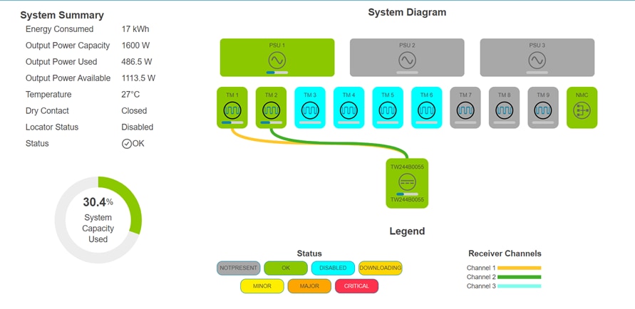
FMPS Management Interface Screenshots

Catalyst 9300 Show Command Outputs
show environment all
In the outputs below, power supply 1 is the 715-watt DC power supply, and power supply 2 is the 1900-watt AC power supply.
| Parameter |
State |
Reading |
| PS1 Vout |
GOOD |
56174 mV |
| PS1 Vin |
GOOD |
48688 mV |
| PS1 CURin |
GOOD |
2363 mA |
| PS1 CURout |
GOOD |
1719 mA |
| PS1 POWin |
GOOD |
116500 mW |
| PS1 POWout |
GOOD |
98250 mW |
| PS1 FAN |
GOOD |
6768 rpm |
| PS2 Vout |
GOOD |
56064 mV |
| PS2 Vin |
GOOD |
205000 mV |
| PS2 CURin |
GOOD |
1477 mA |
| PS2 CURout |
GOOD |
4672 mA |
| PS2 POWin |
GOOD |
299000 mW |
| PS2 POWout |
GOOD |
261500 mW |
| PS2 FAN |
GOOD |
4768 rpm |
show power detail
Power Supply Status
| Power Supply ID |
Status |
System Power |
PoE Power |
Watts |
| A |
OK |
Good |
Good |
715 |
| B |
OK |
Good |
Good |
1900 |
System Power Status
| Module |
State |
Budget |
Instantaneous |
| 1 |
accepted |
240 |
53 |
Power Summary
| Power Type |
Used |
Available |
| System Power |
240 |
455 |
| PoE Power |
323 |
2160 |
| Total Power |
563 |
2615 |
show power inline upoe-plus
| Interface |
Allocated Power |
Utilized Power |
| Gi 1/0/1 |
15.4 |
14.1 |
| Gi 1/0/2 |
15.4 |
14.1 |
| Gi 1/0/3 |
15.4 |
14.2 |
| Gi 1/0/4 |
15.4 |
14.2 |
| Gi 1/0/5 |
15.4 |
14.0 |
| Gi 1/0/6 |
15.4 |
14.0 |
| Gi 1/0/7 |
15.4 |
14.1 |
| Gi 1/0/8 |
15.4 |
13.9 |
| Gi 1/0/9 |
15.4 |
14.0 |
| Gi 1/0/10 |
15.4 |
14.1 |
| Gi 1/0/11 |
15.4 |
14.1 |
| Gi 1/0/12 |
15.4 |
14.0 |
| Gi 1/0/13 |
15.4 |
13.9 |
| Gi 1/0/14 |
15.4 |
13.9 |
| Gi 1/0/15 |
15.4 |
13.9 |
| Gi 1/0/16 |
15.4 |
13.9 |
| Gi 1/0/17 |
15.4 |
13.9 |
| Gi 1/0/18 |
15.4 |
13.9 |
| Gi 1/0/19 |
15.4 |
14.1 |
| Gi 1/0/20 |
15.4 |
13.9 |
| Gi 1/0/21 |
15.4 |
14.1 |
Test 3 with 15-Watt Endpoints and Loss of AC Power Supply
FMPS Management Interface Screenshots

Catalyst 9300 Show Command Outputs
show environment all
Power supply 2, the 1900-watt AC power supply, was removed from the equation to demonstrate FMPS’ capability to serve as a backup.
| Parameter |
State |
Reading |
| PS1 Vout |
GOOD |
56238 mV |
| PS1 Vin |
GOOD |
48125 mV |
| PS1 CURin |
GOOD |
8250 mA |
| PS1 CURout |
GOOD |
6508 mA |
| PS1 POWin |
GOOD |
396500 mW |
| PS1 POWout |
GOOD |
364000 mW |
| PS1 FAN |
GOOD |
6736 rpm |
| PS2 Vout |
FAULTY |
0 mV |
| PS2 Vin |
FAULTY |
0 mV |
| PS2 CURin |
FAULTY |
0 mA |
| PS2 CURout |
FAULTY |
0 mA |
| PS2 POWin |
FAULTY |
0 mW |
| PS2 POWout |
FAULTY |
0 mW |
| PS2 FAN |
FAULTY |
0 rpm |
show power detail
Power Supply Status
| Power Supply ID |
Status |
System Power |
PoE Power |
Watts |
| A |
OK |
Good |
Good |
715 |
| B |
No Input Power |
Bad |
Bad |
1900 |
System Power Status
| Module |
State |
Budget |
Instantaneous |
| 1 |
accepted |
240 |
70 |
Power Summary
| Power Type |
Used |
Available |
| System Power |
240 |
2140 |
| PoE Power |
323 |
475 |
| Total Power |
563 |
2615 |
show power inline upoe-plus
| Interface |
Allocated Power |
Utilized Power |
| Gi 1/0/1 |
15.4 |
14.1 |
| Gi 1/0/2 |
15.4 |
14.1 |
| Gi 1/0/3 |
15.4 |
14.2 |
| Gi 1/0/4 |
15.4 |
14.2 |
| Gi 1/0/5 |
15.4 |
14.0 |
| Gi 1/0/6 |
15.4 |
14.0 |
| Gi 1/0/7 |
15.4 |
14.1 |
| Gi 1/0/8 |
15.4 |
13.9 |
| Gi 1/0/9 |
15.4 |
14.0 |
| Gi 1/0/10 |
15.4 |
14.1 |
| Gi 1/0/11 |
15.4 |
14.1 |
| Gi 1/0/12 |
15.4 |
14.0 |
| Gi 1/0/13 |
15.4 |
13.9 |
| Gi 1/0/14 |
15.4 |
13.9 |
| Gi 1/0/15 |
15.4 |
13.9 |
| Gi 1/0/16 |
15.4 |
14.0 |
| Gi 1/0/17 |
15.4 |
14.0 |
| Gi 1/0/18 |
15.4 |
13.9 |
| Gi 1/0/19 |
15.4 |
14.1 |
| Gi 1/0/20 |
15.4 |
13.9 |
| Gi 1/0/21 |
15.4 |
14.1 |
Test 3 with 90-Watt Endpoints and Two Power Supplies
FMPS Management Interface Screenshots

Catalyst 9300 Show Command Outputs
show environment all
In the outputs below, power supply 1 is the 715-watt DC power supply, and power supply 2 is the 1900-watt AC power supply.
| Parameter |
State |
Reading |
| PS1 Vout |
GOOD |
56174 mV |
| PS1 Vin |
GOOD |
47563 mV |
| PS1 CURin |
GOOD |
11344 mA |
| PS1 CURout |
GOOD |
8563 mA |
| PS1 POWin |
GOOD |
540000 mW |
| PS1 POWout |
GOOD |
499500 mW |
| PS1 FAN |
GOOD |
5568 rpm |
| PS2 Vout |
GOOD |
56014 mV |
| PS2 Vin |
GOOD |
200500 mV |
| PS2 CURin |
GOOD |
6594 mA |
| PS2 CURout |
GOOD |
22250 mA |
| PS2 POWin |
GOOD |
1314000 mW |
| PS2 POWout |
GOOD |
1250000 mW |
| PS2 FAN |
GOOD |
10432 rpm |
show power detail
Power Supply Status
| Power Supply ID |
Status |
System Power |
PoE Power |
Watts |
| A |
OK |
Good |
Good |
715 |
| B |
OK |
Good |
Good |
1900 |
System Power Status
| Module |
State |
Budget |
Instantaneous |
| 1 |
accepted |
240 |
102 |
Power Summary
| Power Type |
Used |
Available |
| System Power |
240 |
455 |
| PoE Power |
1890 |
2160 |
| Total Power |
2130 |
2615 |
show power inline upoe-plus
| Interface |
Allocated Power |
Utilized Power |
| Gi 1/0/1 |
90.0 |
81.1 |
| Gi 1/0/2 |
90.0 |
81.3 |
| Gi 1/0/3 |
90.0 |
80.9 |
| Gi 1/0/4 |
90.0 |
81.0 |
| Gi 1/0/5 |
90.0 |
80.7 |
| Gi 1/0/6 |
90.0 |
81.4 |
| Gi 1/0/7 |
90.0 |
80.9 |
| Gi 1/0/8 |
90.0 |
80.4 |
| Gi 1/0/9 |
90.0 |
80.8 |
| Gi 1/0/10 |
90.0 |
80.4 |
| Gi 1/0/11 |
90.0 |
80.7 |
| Gi 1/0/12 |
90.0 |
80.5 |
| Gi 1/0/13 |
90.0 |
80.7 |
| Gi 1/0/14 |
90.0 |
80.4 |
| Gi 1/0/15 |
90.0 |
80.6 |
| Gi 1/0/16 |
90.0 |
80.7 |
| Gi 1/0/17 |
90.0 |
80.7 |
| Gi 1/0/18 |
90.0 |
80.4 |
| Gi 1/0/19 |
90.0 |
81.4 |
| Gi 1/0/20 |
90.0 |
80.4 |
| Gi 1/0/21 |
90.0 |
80.9 |
Test 3 with 90-Watt Endpoints and Loss of AC Power Supply
FMPS Management Interface Screenshots

Catalyst 9300 Show Command Outputs
show environment all
| Parameter |
State |
Reading |
| PS1 Vout |
GOOD |
56238 mV |
| PS1 Vin |
GOOD |
47875 mV |
| PS1 CURin |
GOOD |
7125 mA |
| PS1 CURout |
GOOD |
5594 mA |
| PS1 POWin |
GOOD |
342500 mW |
| PS1 POWout |
GOOD |
312500 mW |
| PS1 FAN |
GOOD |
5568 rpm |
| PS2 Vout |
FAULTY |
0 mV |
| PS2 Vin |
FAULTY |
0 mV |
| PS2 CURin |
FAULTY |
0 mA |
| PS2 CURout |
FAULTY |
0 mA |
| PS2 POWin |
FAULTY |
0 mW |
| PS2 POWout |
FAULTY |
0 mW |
| PS2 FAN |
FAULTY |
0 rpm |
show power detail
Power Supply Status
| Power Supply ID |
Status |
System Power |
PoE Power |
|
| A |
OK |
Good |
Good |
715 |
| B |
Unknown |
Bad |
Bad |
Unknown |
System Power Status
| Module |
State |
Budget |
Instantaneous |
| 1 |
accepted |
240 |
71 |
Power Summary
| Power Type |
Used |
Available |
| System Power |
240 |
2140 |
| PoE Power |
450 |
475 |
| Total Power |
690 |
2615 |
show power inline upoe-plus
| Interface |
Allocated Power |
Utilized Power |
| Gi 1/0/7 |
90.0 |
80.0 |
| Gi 1/0/10 |
90.0 |
80.1 |
| Gi 1/0/11 |
90.0 |
80.4 |
| Gi 1/0/12 |
90.0 |
80.3 |
| Gi 1/0/13 |
90.0 |
80.5 |
Test 3 was successful and validates FMPS successfully delivers the requisite 715 watts to the switch with the following parameters of the FMPS:
● 1 FMPS power supply, has capacity to provide 1600 watts, exceeding the required 715 watts
● 2 Transmitters, each Transmitter can only provide 600 watts, so requires two
● 1 Receiver, each Receiver has three input channels that can receive power from the Transmitters, only one required to receive input from two Transmitters
● 1000 meters of 16 AWG multiconductor cable
At 1000 meters, the FMPS delivered the full 715 watts required to load the power supply on the switch to maximum capacity. This performance was conclusively demonstrated by the power summary from the "show power detail" command as well as the FMPS management console.
When AC power was lost to the switch, FMPS sustained operations of the DC power supply to power both the switch and PoE endpoints, showing FMPS can serve as a solution to achieve power redundancy at remote locations.
When the load on the interfaces were increased to 90-watt endpoints, when AC power was lost, the switch remained operational, but power was shed and the interfaces where port priority was configured to high, interfaces 11, 12, and 13 in this test, those endpoints were unimpacted while the remaining wattage available was used to power the endpoints on interfaces 7 and 10.
A single FMPS Transmitter connected to a centralized UPS can support four distributed 9300 switches up to 1000 meters away from a centralized point. For more details, see the topic Scalability.
Dual Homing Power And Network Architecture
This architectural design is well-suited for critical applications where network uptime and reliability are paramount. From a power perspective, using two FMPS Receivers provides redundant power supply to two 9300 switches, where it reduces the risk of a single point of failure. It allows for maintenance on a Receiver without affecting the operation of the switch.
From a network perspective, using two 9300 switches helps ensure that a network remains operational even if one part of the network fails. It can also help manage network load by distributing traffic across multiple connects.
Having two switches will allow for more PoE devices to also be connected and powered by FMPS, should the need arise for additional endpoints to be deployed in a space.
Test 4: FMPS to DC Power Supply in Dual Homing Configuration
For Test 4, the FMPS will provide DC power to the C9300 in a dual homing configuration, where two Receivers will each power one dedicated power supply on the switch, so that one Receiver does not act as a single point of failure and the FMPS architecture provides power resiliency.
In conjunction with the power redundancy, the “power inline port priority high” command was used with the 90-watt endpoints to ensure that during the power shedding, the interfaces configured with high priority would remain unimpacted while the remainder of the interfaces connected to PoE endpoints would shed power and enter into a power-deny state as a result of loss of power.
The desired outcome for the test is:
● C9300 to successfully provide power to 21 PoE endpoints drawing 15 watts
◦ After a loss of power to one of the power supplies, the switch and PoE endpoints will be unimpacted
● C9300 to successfully provide power to 13 PoE endpoints drawing 90 watts
◦ After a loss of power to one of the power supplies, the switch and PoE endpoints connected to interfaces with high port priority remain unimpacted, while the others are shed due insufficient PoE power
Dual-homing architectures would be implemented in high-availability environments where continuous power is crucial for business operations, such as financial services, healthcare, and cloud service providers.
The dual homing configuration achieves redundancy by allowing the switches to be powered by two Receivers rather than one, alleviating the sole responsibility of powering the switch to one single Receiver.
|
|
|
|
| Chassis Quantity |
1 |
Chassis Quantity |
| Power Supply Quantity |
2 |
Power Supply Quantity |
| Transmitter Quantity |
6 |
Transmitter Quantity |
| Receivers |
2 |
Receivers |
| Cable Length |
450 m |
Cable Length |
| Cable Gauge |
16 AWG |
Cable Gauge |
| Power Supply Type |
DC |
Power Supply Type |
| Power Supply Quantity |
2 |
Power Supply Quantity |
| Homing Architecture |
dual |
Homing Architecture |
Bill of Materials Panduit
| Item Name |
PID |
Quantity |
| FMPS Chassis |
PXTC1ARA |
1 |
| FMPS Power Supply Unit |
PXU1AJANNNXX |
2 |
| FMPS Transmitter |
PXTM1AF |
6 |
| FMPS Receiver |
PXR1AJD |
2 |
| Class 4 Copper Cable |
PXUP316ARD-UQ |
1 |
Bill of Materials Cisco
| Item Name |
PID |
Quantity |
| Catalyst 9300-24H |
C9300-24H-E |
1 |
| 715 Watt DC Power Supply Unit |
PWR-C1-715WDC= |
4 |
Test 4 with 15-Watt Endpoints and Two Power Supplies
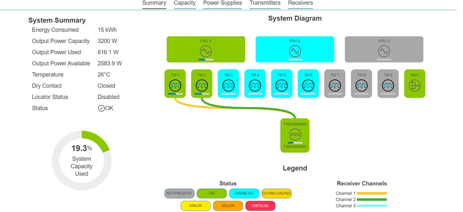
FMPS Management Interface Screenshots
Catalyst 9300 Show Command Outputs
show environment all
| Parameter |
State |
Reading |
| PS1 Vout |
GOOD |
56174 mV |
| PS1 Vin |
GOOD |
48500 mV |
| PS1 CURin |
GOOD |
4023 mA |
| PS1 CURout |
GOOD |
3047 mA |
| PS1 POWin |
GOOD |
193750 mW |
| PS1 POWout |
GOOD |
171000 mW |
| PS1 FAN |
GOOD |
6800 rpm |
| PS2 Vout |
GOOD |
56174 mV |
| PS2 Vin |
GOOD |
49500 mV |
| PS2 CURin |
GOOD |
4234 mA |
| PS2 CURout |
GOOD |
3438 mA |
| PS2 POWin |
GOOD |
217000 mW |
| PS2 POWout |
GOOD |
191250 mW |
| PS2 FAN |
GOOD |
5328 rpm |
show power detail
Power Supply Status
| Power Supply ID |
Status |
System Power |
PoE Power |
Watts |
| A |
OK |
Good |
Good |
715 |
| B |
OK |
Good |
Good |
715 |
System Power Status
| Module |
State |
Budget |
Instantaneous |
| 1 |
accepted |
240 |
67 |
Power Summary
| Power Type |
Used |
Available |
| System Power |
240 |
240 |
| PoE Power |
323 |
1190 |
| Total Power |
563 |
1430 |
show power inline upoe-plus
| Interface |
Allocated Power |
Utilized Power |
| Gi 1/0/1 |
15.4 |
12.8 |
| Gi 1/0/2 |
15.4 |
14.0 |
| Gi 1/0/3 |
15.4 |
14.2 |
| Gi 1/0/4 |
15.4 |
14.2 |
| Gi 1/0/5 |
15.4 |
14.1 |
| Gi 1/0/6 |
15.4 |
14.1 |
| Gi 1/0/7 |
15.4 |
14.1 |
| Gi 1/0/8 |
15.4 |
14.0 |
| Gi 1/0/9 |
15.4 |
14.0 |
| Gi 1/0/10 |
15.4 |
14.1 |
| Gi 1/0/11 |
15.4 |
14.1 |
| Gi 1/0/12 |
15.4 |
14.0 |
| Gi 1/0/13 |
15.4 |
13.9 |
| Gi 1/0/14 |
15.4 |
13.9 |
| Gi 1/0/15 |
15.4 |
13.9 |
| Gi 1/0/16 |
15.4 |
13.9 |
| Gi 1/0/17 |
15.4 |
13.9 |
| Gi 1/0/18 |
15.4 |
13.9 |
| Gi 1/0/19 |
15.4 |
14.1 |
| Gi 1/0/20 |
15.4 |
13.9 |
| Gi 1/0/21 |
15.4 |
14.0 |
Test 4 with 15-Watt Endpoints and Loss of One DC Power Supply
FMPS Management Interface Screenshots
Catalyst 9300 Show Command Outputs
show environment all
The output below shows the result of a simulated failure on the Receiver powering power supply 2.
| Parameter |
State |
Reading |
| PS1 Vout |
GOOD |
56238 mV |
| PS1 Vin |
GOOD |
48125 mV |
| PS1 CURin |
GOOD |
8219 mA |
| PS1 CURout |
GOOD |
6508 mA |
| PS1 POWin |
GOOD |
396500 mW |
| PS1 POWout |
GOOD |
365000 mW |
| PS1 FAN |
GOOD |
6800 rpm |
| PS2 Vout |
FAULTY |
0 mV |
| PS2 Vin |
FAULTY |
0 mV |
| PS2 CURin |
FAULTY |
0 mA |
| PS2 CURout |
FAULTY |
0 mA |
| PS2 POWin |
FAULTY |
0 mW |
| PS2 POWout |
FAULTY |
0 mW |
| PS2 FAN |
FAULTY |
0 rpm |
show power detail
Power Supply Status
| Power Supply ID |
Status |
System Power |
PoE Power |
Watts |
| A |
OK |
Good |
Good |
715 |
| B |
No Input Power |
Bad |
Bad |
715 |
System Power Status
| Module |
State |
Budget |
Instantaneous |
| 1 |
accepted |
240 |
70 |
Power Summary
| Power Type |
Used |
Available |
| System Power |
240 |
955 |
| PoE Power |
323 |
475 |
| Total Power |
563 |
1430 |
show power inline upoe-plus
| Interface |
Allocated Power |
Utilized Power |
| Gi 1/0/1 |
15.4 |
14.1 |
| Gi 1/0/2 |
15.4 |
14.1 |
| Gi 1/0/3 |
15.4 |
14.3 |
| Gi 1/0/4 |
15.4 |
14.2 |
| Gi 1/0/5 |
15.4 |
14.1 |
| Gi 1/0/6 |
15.4 |
14.1 |
| Gi 1/0/7 |
15.4 |
14.1 |
| Gi 1/0/8 |
15.4 |
13.9 |
| Gi 1/0/9 |
15.4 |
13.9 |
| Gi 1/0/10 |
15.4 |
14.1 |
| Gi 1/0/11 |
15.4 |
14.1 |
| Gi 1/0/12 |
15.4 |
14.1 |
| Gi 1/0/13 |
15.4 |
13.9 |
| Gi 1/0/14 |
15.4 |
13.9 |
| Gi 1/0/15 |
15.4 |
13.9 |
| Gi 1/0/16 |
15.4 |
13.9 |
| Gi 1/0/17 |
15.4 |
13.9 |
| Gi 1/0/18 |
15.4 |
13.9 |
| Gi 1/0/19 |
15.4 |
14.1 |
| Gi 1/0/20 |
15.4 |
13.9 |
| Gi 1/0/21 |
15.4 |
14.0 |
Test 4 with 90-Watt Endpoints and Two Power Supplies
FMPS Management Interface Screenshots
Catalyst 9300 Show Command Outputs
show environment all
| Parameter |
State |
Reading |
| PS1 Vout |
GOOD |
56432 mV |
| PS1 Vin |
GOOD |
47875 mV |
| PS1 CURin |
GOOD |
12422 mA |
| PS1 CURout |
GOOD |
9734 mA |
| PS1 POWin |
GOOD |
597000 mW |
| PS1 POWout |
GOOD |
545000 mW |
| PS1 FAN |
GOOD |
7456 rpm |
| PS2 Vout |
GOOD |
56238 mV |
| PS2 Vin |
GOOD |
47938 mV |
| PS2 CURin |
GOOD |
12922 mA |
| PS2 CURout |
GOOD |
10063 mA |
| PS2 POWin |
GOOD |
620000 mW |
| PS2 POWout |
GOOD |
566000 mW |
| PS2 FAN |
GOOD |
6736 rpm |
show power detail
Power Supply Status
| Power Supply ID |
Status |
System Power |
PoE Power |
Watts |
| A |
OK |
Good |
Good |
715 |
| B |
OK |
Good |
Good |
715 |
System Power Status
| Module |
State |
Budget |
Instantaneous |
| 1 |
accepted |
240 |
65 |
Power Summary
| Power Type |
Used |
Available |
| System Power |
240 |
240 |
| PoE Power |
1170 |
1190 |
| Total Power |
1410 |
1430 |
show power inline upoe-plus
| Interface |
Allocated Power |
Utilized Power |
| Gi 1/0/1 |
90.0 |
80.6 |
| Gi 1/0/2 |
90.0 |
80.9 |
| Gi 1/0/3 |
90.0 |
80.5 |
| Gi 1/0/4 |
90.0 |
80.6 |
| Gi 1/0/5 |
90.0 |
80.3 |
| Gi 1/0/6 |
90.0 |
80.9 |
| Gi 1/0/7 |
90.0 |
80.4 |
| Gi 1/0/8 |
90.0 |
80.0 |
| Gi 1/0/9 |
90.0 |
80.3 |
| Gi 1/0/10 |
90.0 |
80.0 |
| Gi 1/0/11 |
90.0 |
80.4 |
| Gi 1/0/12 |
90.0 |
80.0 |
| Gi 1/0/13 |
90.0 |
80.0 |
Test 4 with 90-Watt Endpoints and Loss of One DC Power Supply
FMPS Management Interface Screenshots
Catalyst 9300 Show Command Outputs
show environment all
The output below shows the result of a simulated failure on the Receiver powering power supply 2.
| Parameter |
State |
Reading |
| PS1 Vout |
GOOD |
56432 mV |
| PS1 Vin |
GOOD |
48750 mV |
| PS1 CURin |
GOOD |
7258 mA |
| PS1 CURout |
GOOD |
5555 mA |
| PS1 POWin |
GOOD |
352000 mW |
| PS1 POWout |
GOOD |
316000 mW |
| PS1 FAN |
GOOD |
11392 rpm |
| PS2 Vout |
FAULTY |
0 mV |
| PS2 Vin |
FAULTY |
0 mV |
| PS2 CURin |
FAULTY |
0 mA |
| PS2 CURout |
FAULTY |
0 mA |
| PS2 POWin |
FAULTY |
0 mW |
| PS2 POWout |
FAULTY |
0 mW |
| PS2 FAN |
FAULTY |
0 rpm |
show power detail
Power Supply Status
| Power Supply ID |
Status |
System Power |
PoE Power |
Watts |
| A |
OK |
Good |
Good |
715 |
| B |
No Input Power |
Bad |
Bad |
715 |
System Power Status
| Module |
State |
Budget |
Instantaneous |
| 1 |
accepted |
240 |
75 |
Power Summary
| Power Type |
Used |
Available |
| System Power |
240 |
955 |
| PoE Power |
450 |
475 |
| Total Power |
780 |
1430 |
show power inline upoe-plus
| Interface |
Allocated Power |
Utilized Power |
| Gi 1/0/11 |
90.0 |
80.4 |
| Gi 1/0/12 |
90.0 |
80.0 |
| Gi 1/0/13 |
90.0 |
80.0 |
Test 4 was successful and confirms FMPS is able to act as a backup solution to itself by using multiple Receivers to power a PoE switch with 1430 watts with the following parameters of the FMPS:
● 2 FMPS power supply, tested power redundancy, necessitating the use of two power supplies
● 6 Transmitters, each Transmitter can only provide 600 watts, simulated the use of two separate Receivers, requiring 6 Transmitters
● 2 Receivers, simulated power loss to single Receiver to demonstrate dual-homing architecture that one Receiver can power a power supply on multiple switches
● 450 meters of 16 AWG multiconductor cable,distance reduced to minimize power loss
Each Receiver in the FMPS was able to deliver all requisite 715 watts across 450 meters to load each power supply on the switch to full capacity, as evidenced by the power summary from the “show power detail” command as well as FMPS management console corroborating said state of PoE switches.
Power redundancy was successful in keeping the switch operational while also powering all the 15-watt endpoints when power to a DC power supply was lost through the failure of one Receiver.
When the load on the interfaces were increased to 90-watt endpoints, when one DC power supply lost power, the switch remained operational, but power was shed and the interfaces where port priority was configured to high, interfaces 11, 12, and 13 in this test, remained unimpacted.
The tests conducted and outcomes observed have shown the capability of FMPS to play an integral role in a PoE solution. The battery of tests conducted to validate its capabilities shows that so long as the requisite components and modules are present in the FMPS to ensure the Receiver can draw the necessary power, it can deliver it as required, as evidenced by the operations of both the C9300 as well as the PoE endpoints connected to it.
The amount of power expected to be delivered to the Receivers relative to the distance of the 16-AWG multiconductor cable in the graph referenced in Distance/Length of Cables was successfully delivered to the Receivers.
There are additional factors to consider when designing the power delivery infrastructure using FMPS. Such things include, but are not limited to:
● Selected cable must be UL 1400-2 certified and must be listed under the Panduit UL 1400-1 listing. Contact Panduit for the most up to date listed cables.
● Gauge of multiconductor cable connecting Transmitter to Receiver distance from headend/MDF to remote location where Receivers will be deployed environmental conditions to which FMPS components will be exposed to requirements such as redundancy and scalability.
As evidenced in the tests conducted, many of the factors can be adjusted to fit the needs of a deployment as simple as powering a single DC power supply on a PoE switch to power connected PoE endpoints, to as complex as implementing a dual-homing architecture to provide power redundancy to multiple switches to eliminate a single point of failure. The modularity and scalability of the individual components allows for FMPS to be deployed to meet immediate needs while permitting for growth in the future both near and distant.
Panduit's FMPS, combined with Cisco Catalyst 9300 PoE switches, extends network reach and delivers high-wattage power over long distances, allowing Cisco switches to maintain performance and utilize PoE features effectively. FMPS not only enhances network flexibility but also simplifies installation by reducing local power source requirements. The integrated power and network management tools support efficient distributed network architectures.