Cisco and Thinlabs Implementation Guide
Available Languages
Bias-Free Language
The documentation set for this product strives to use bias-free language. For the purposes of this documentation set, bias-free is defined as language that does not imply discrimination based on age, disability, gender, racial identity, ethnic identity, sexual orientation, socioeconomic status, and intersectionality. Exceptions may be present in the documentation due to language that is hardcoded in the user interfaces of the product software, language used based on RFP documentation, or language that is used by a referenced third-party product. Learn more about how Cisco is using Inclusive Language.
- US/Canada 800-553-2447
- Worldwide Support Phone Numbers
- All Tools
 Feedback
 Feedback
Purpose and Overview
PoE Displays and Computing Solutions by Thinlabs and Cisco
Overview:
Thinlabs, in collaboration with Cisco’s Engineering Alliance, delivers Power over Ethernet (PoE) compute and display solutions using Cisco’s PoE networking infrastructure. By integrating power and data transmission (including device management) over a single Ethernet cable, this partnership harnesses IEEE 802.3bt standards-based Cisco’s UPoE+ switches (providing up to 90 watts per interface) to power Thinlabs’ all-in-one computers and mini-PCs, enabling up to 75% (changed) energy efficiency, cost savings, and simplified deployment and management.
Problem Facing the Industry:
While essential electrical systems such as lighting, Wi-Fi, security, and HVAC controls increasingly utilize PoE, traditional computing units still depend on separate electrical wiring and infrastructure, leading to higher costs, complex material needs, and energy consumption.
How Thinlabs Solves the Problem:
With over 60,000 PoE computers deployed globally, Thinlabs eliminates the need for traditional electrical infrastructure, enhancing efficiency, safety, and sustainability. Their PoE-powered devices, including all-in-one computers (15" to 55" displays) and mini-PCs, consume roughly 25% of the power of conventional computers.
Key features include:
● Potential Energy Savings
● High Performance
◦ Up to 8-core processors, 64 GB RAM, and compatibility with Windows 11 Professional and other operating systems.
● Additional Benefits
◦ Lower cooling requirements due to reduced heat generation.
◦ Decreased dependency on UPS backups.
◦ Faster, more cost-effective reconfiguration of computing setups.
● Health, Safety, and Sustainability
◦ PoE solutions eliminate high-voltage wiring, improving workplace safety and significantly reducing carbon footprints by reducing the need of system power auxiliaries.
Implementation Guide Overview
This architecture validation seeks to provide guidelines to implement a PoE solution comprised of Thinlabs products and Cisco’s line of PoE switches to deliver the requisite power. The use cases covered in this document will be to power and operate a computer and display(s) over a standard Cat5e ethernet cable.
Intended Audience
The intended audience for this document is for all parties involved in considering, purchasing, designing, and implementing a PoE solution with Thinlabs’ hardware portfolio, including but not limited to the following:
● Project and/or account managers
● MEP (mechanical, electrical, plumbing) engineers and/or partners
● System integrators
● Supply vendors
Components Used for Validations
Thinlabs Components
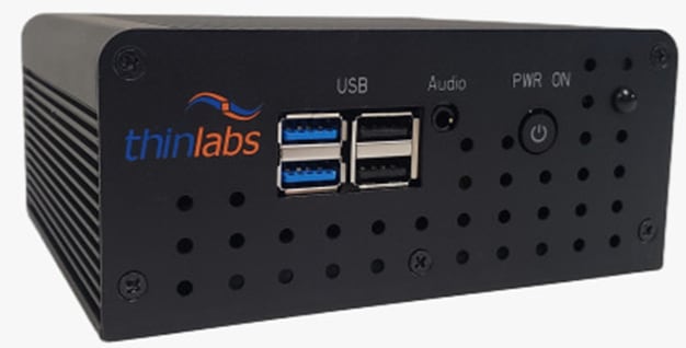
Nucleus Mini-PC
The Nucleus Mini-PC comes in a variety of configurations but the two selected to test in these validations are the TL1205P and the TL1215P. The storage and memory are modular and not directly soldered to the motherboard, so they can be configured to meet the needs of the user, however the processor, and the input output options are fixed.
The configurations of the Mini-PCs tested are listed in the table below:
Table 1. Thinlabs Nucleus Mini-PC Specifications Validated
| Model |
AMD Processor Model |
Cores |
Threads |
RAM (GB) |
Ports |
SSD Storage Capacity (GB) |
| TL1205P |
R1305G |
2 |
4 |
16 |
2 x USB 2.0 2 x USB 3.0 3 x USB-C to Power/Audio/Video output |
500 |
| TL1215P |
V2516 |
6 |
12 |
32 |
2 x USB 2.0 2 x USB 3.0 4 x USB-C to Power/Audio/Video output
|
500 |
Additional information regarding the Thinlabs Nucleus Mini-PC can be found in the link below:
https://us.thinlabs.com/product/nucleus-poe-fanless-mini-pc-solutions/
All-In-One PC
Thinlabs innovatively manufactures All-In-One PCs, seamlessly integrating the processing power and display into a unified chassis. This design streamlines setup and reduces cable clutter. Their TL2805P model, selected for testing, exemplifies this concept. It features a convenient 24-inch touch display housing the same internal specifications as their compact TL1205P Nucleus Mini-PC. The entire system is powered by a single Power over Ethernet (PoE) cable, further simplifying deployment and potentially reducing energy consumption.
There are a variety of configurations available to meet the solution needs where not only the specifications of the components, but also the size of the display. The displays range in size from 19 inches all the way to 55 inches, with more sizes coming in the near future.

Additional information regarding the Thinlabs All-In-One PC can be found in the link below:
https://us.thinlabs.com/product/single-dual-triple-screen-poe-computers/
PoE Displays
Thinlabs manufactures digital signage solutions that can be powered in three ways:
● The displays can be powered through built in PoE interfaces on the displays
● The displays can be powered via USB-C form factor cable connected to Thinlabs PC’s
● The displays can be powered through a 12V power adapter
The two displays tested are:
● 24-inch 1080p, TLM245
● 27-inch 2160p (4K), TL2736
They were both powered via passthrough using the USB-C form factor cable designed and made by Thinlabs.
In the same regard with the All-In-One PC’s, the PoE displays can be custom-tailored to meet the needs of the user with regards to resolution, power delivery, and display size.

Additional information regarding the Thinlabs PoE displays can be found in the link below:
https://us.thinlabs.com/product/digital-signage-solutions/
Cisco Components
The following section will outline the individual components from Cisco. It is important to note that the devices referenced below are manufactured by Cisco hence respective product identifiers (PID) and stock keeping units (SKU) provided by Cisco will be listed.
Cisco Catalyst 9300
Cisco Catalyst C9300-48H switch has been provisioned to provide UPoE+ power and 1 gigabit speed on data connectivity. This provisioning ensures that the Thinlabs devices under test can access up to 90 watts of power, compliant with the IEEE 802.3bt standard, thereby enabling comprehensive evaluation of their performance envelope.
Additional information regarding the Cisco Catalyst 9300 portfolio of switches can be found on Cisco’s C9300 products datasheet in the link below:
The switch is provisioned with IOS XE 17.15.2 software, for which the release notes can be found in the link below:
Power Supply
The selection of a power supply unit for the Catalyst 9300 is primarily governed by the aggregate power budget necessitated by the Power over Ethernet (PoE) solution/endpoints. The power supplies for Cisco Catalyst 9300 switches are available in both Alternating Current (AC) and Direct Current (DC) input configurations, with a spectrum of wattage ratings offered within the AC models.
It is important to note that the power supplies will always budget a certain portion of the total power available to power the switch hardware and software components, while the remainder will be made allocated to PoE budget that can be distributed to the PoE endpoints. The system power demands will be predicated by the model of the Catalyst 9300.
Additional information regarding the power supplies for the Catalyst 9300 portfolio of switches can be found on Cisco’s datasheet in the link below:
Power Budget Calculation
In the Catalyst 9300 datasheet linked above, table 4 provides the power available for PoE with the matching power supply configuration. In designing the power delivery architecture, some of the factors to consider when selecting the switch model and power supplies are:
● How many switch interfaces will be providing PoE power?
● What is the PoE class for each PoE endpoint?
● What is the total power requirement for all connected devices, including the Catalyst switch itself and the PoE-powered solutions to achieve the desired outcome?
● What is the highest power that the PoE solution can draw in a normal and max loads?
● How will the total available power be distributed to each interface based on PoE endpoint class?
● How many switches will be required to meet the total power requirement?
● Is redundancy required?
● Is the system scalable for immediate future needs?
Including the factors above, there are applicable building regulations, standards, and code that will influence the overall system design. Designing the PoE network will require strong collaboration to ensure that the DC PoE power can be effectively distributed to realize maximum value and achieve optimal efficiency, while remaining compliant with all the required regulations to operate safely.
Cabling Components
The following section outlines the cables used in conducting the validations for this document.
22AWG Cat5e Ethernet Cables
Based on the 802.3bt standards, many cable manufacturers have made ethernet cables optimized for PoE power delivery with thicker 22AWG cables that can minimize power loss over the length of the connection. In this setup we tested with two cat5e cables measured 5 meters and 100 meters in length. The 5 meters was used to demonstrate a shorter homerun that would experience near zero power loss, while 100 meters was used to demonstrate viability of a home run at the maximum length governed by the 802.3bt standards.
Thinlabs USB-C Form Factor Cables
Thinlabs proprietary USB-C cables are connectors that are capable of delivering both power and DisplayPort data from the PC to the displays. The means to deliver both power and DisplayPort data through the same USB-C form factor connection is patent-pending at the time of writing.
The USB-C standard enables the cables to deliver the power necessary to turn on the connected displays.
Note: Connecting a standard USB-C cable will not work with the solution given the proprietary nature of the cables used in Thinlabs PoE compute solutions.
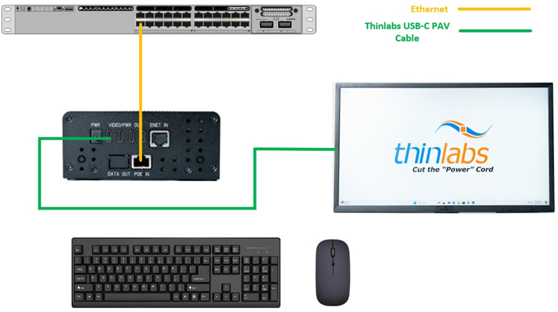
Reference Architecture
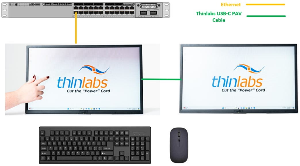
To demonstrate the simplicity, operability and viability of PoE computers as a viable solution in the PC market, the following elements were deployed:
● PC
◦ Either the Nucleus Mini-PC or All-In-One PC
● Thinlabs External display
● Generic keyboard and mouse
The diagram of the overall solution can be found below:
Validation Methodology
Functional Operation
To validate the functional operation, the desired outcomes are below:
● Sustained idle operations
◦ The computer will be in an idle state and maintain power and operations with no load on the computer
◦ The solution will have to remain intact for a period of 30 minutes to be successful
● Sustained processor-stressed operations
◦ The computer will be stressed using Prime95 as the load on the processor and solution will maintain power and operations
◦ The solution will have to remain intact for a period of 30 minutes to be successful
The solutions will be deployed using variables that could potentially influence the performance of the solution. The brightness of the displays will be tuned from the minimum brightness to the maximum brightness to influence the power draw of the solution accordingly.
Since Thinlabs’ PCs are certified to work in ambient temperatures between 41 and 95 degrees Fahrenheit, the tests will be conducted twice, once with ambient temperature of 60 degrees, and once more at 95 degrees.
Catalyst 9300 Switch PSE Operational State
For simplicity, the Catalyst 9300 switch command line interface will be used to confirm that the switch is allocating and delivering the required power to the Thinlabs computers under the 802.3bt standards. There are several commands where the outputs can verify the switch is allocating enough power to run its own systems as well as deliver power to the connected PoE endpoints, however the command “show power inline GigabitEthernet X/X/X detail” provides the near real-time power draw on the interface connected to the PoE computer that will provide the most conclusive evidence sought after in these tests.
Here are some insights the following command output provides:
● PoE Configuration and Status
● Power Allocation and Consumption
● Power Negotiation
● PoE Capabilities and Features
● PoE interface Counters and Statistics
These outputs will provide tremendous value when confirming actual power draw and help to effectively design and operate the PoE infrastructure effectively.
A sample of the output of the command is shown below:
Access9300#show power inline giga 1/0/2 detail
Interface: Gi1/0/2
Inline Power Mode: auto
Operational status (Alt-A,B): on,on
Device Detected: yes
Device Type: Ieee PD
Connection Check: SS
IEEE Class (Alt-A,B): 8
Physical Assigned Class (Alt-A,B): 8
Discovery mechanism used/configured: Ieee and Cisco
Police: off
Power Allocated
Admin Value: 90.0
Power drawn from the source: 90.0
Power available to the device: 90.0
Allocated Power (Alt-A,B): 90.0
Actual consumption
Measured at the port(watts) (Alt-A,B): 9.7
Maximum Power drawn by the device since powered on: 11.6
Absent Counter: 0
Over Current Counter: 0
Short Current Counter: 0
Invalid Signature Counter: 0
Power Denied Counter: 0
Power Negotiation Used: IEEE 802.3bt LLDP
LLDP Power Negotiation --Sent to PD-- --Rcvd from PD--
Power Type: Type 2 PSE Type 2 PD
Power Source: Primary PSE
Power Priority: high low
PD 4PID: 0 0
Requested Power(W): 71.3 71.3
Allocated Power(W): 71.3 71.3
Requested Power ModeA(W): 0.0 0.0
Allocated Power ModeA(W): 0.0 0.0
Requested Power ModeB(W): 0.0 0.0
Allocated Power ModeB(W): 0.0 0.0
PSE Powering Status: 4 pair SS PD Ignore
PD Powering Status: Ignore SS PD
PSE Power Pair ext: Both Alternatives Ignore
DS Class Mode A ext: SS PD Ignore
DS Class Mode B ext: SS PD Ignore
SS Class ext: Class 8 Class 8
PSE Type ext: Type 4 PSE Type 4 SS PD
PSE Max Avail Power: 71.3 0.0
PSE Auto Class Supp: No No
PD Auto Class Req: No No
PD Power Down Req: No No
PD Power Down Time(sec): 0 0
Four-Pair PoE Supported: Yes
Spare Pair Power Enabled: Yes
Four-Pair PD Architecture: Shared
Perpetual POE Enabled: TRUE
Fast POE Enabled: TRUE
The output shown above confirms that the switch (PSE) is successfully negotiating with the Thinlabs powered devices (PD) to allocate the desired power for PoE and also provide real-time power draw at the time the command was executed.
Additional information regarding the commands for software version 17.15.2 can be found below:
Catalyst 9300
This section provides implemented configuration on the switch (PSE).
Global Configurations
Global configuration on a Cisco switch refers to the mode in which you can configure settings that apply to the entire switch, rather than just a specific interface or feature.
This section will provide the recommended configurations at the global level of the switch.
Step 1. Configure a VLAN for PoE network
configure terminal
vlan 15
description Thinlabs PoE network
Step 2. Configure interface Vlan/SVI
configure terminal
interface vlan 15
description Thinlabs PoE network
ip address 10.254.17.17 255.255.255.240
Step 3. Enable lldp
configure terminal
lldp run
LLDP provides a standardized way for network devices to advertise their identity, capabilities, and other information to neighboring devices. In the context of PoE, LLDP (and especially LLDP-MED) adds significant intelligence.
Step 4. Enable cdp
configure terminal
cdp run
CDP provides similar basic PoE power negotiation and dynamic updates as LLDP.
The aforementioned configurations placed the Thinlabs devices in Vlan 15 with a 10.254.17.16/28 IP network. The configurations documented here are essentials for the Thinlabs device to operate with power and data connectivity, other configurations such as high availability, security can be added based on the overall network design.
Cisco Recommended Catalyst Switch Features to Consider
Cisco’s Catalyst 9300 switches have features developed for Smart Buildings and PoE specific use cases, especially PoE specific features that can optimize and enhance PoE solutions. This section will outline a few of these features.
StackPower
Cisco StackPower, a key feature of the Catalyst 9300 series, enables the aggregation of power from the operating power supplies of up to four stacked switches into a unified, larger power pool. This aggregated resource provides redundancy, ensuring that a switch and its connected PoE devices remain operational despite a catastrophic power supply failure within the stack.
For example, if a standalone Catalyst C9300-48H switch has two 1,100-watt power supplies, it will have 1,922 watts available for PoE power. If the switch is deployed in a PoE lighting solution where 15 interfaces are using 90 watts, the solution requires 1,350 watts for PoE and a single power supply would be insufficient, so power shedding will occur where the switch will begin to cut power to some interfaces in an effort to keep itself operational.
However, if StackPower is implemented and the switch belonged to a stack with another switch that also had two 1,100-watt power supplies, the total available power to the solution would be 4,400 watts. If both switches had the same PoE load, the combined PoE power requirement would be 2,700 watts. If a single power supply on either switch failed, the remaining three power supplies in the stack would be more than sufficient to keep both PoE lighting solutions operational.
Additional information regarding StackPower can be found below:
Port Priority
On Cisco Catalyst switches that support Power over Ethernet (PoE), PoE port priority is a feature that allows network admins to prioritize the allocation of PoE power to certain ports over others when the switch's total power budget is being exceeded.
In the event of power shedding, when the switch begins turning off loads to prioritize firstly the switches system power and PoE interfaces, the interfaces with low priority, which is the default value, will be the first to be turned off. However, if there’re critical devices that need to remain operational despite component failure, it is recommended to configure the port with the commands as shown below to increase the priority on that respective port to high.
configure terminal
interface GigabitEthernet X/X/X
power inline port priority high
Putting an interface to high priority will also configure the switch to prioritize allocating available PoE power to those with high priority before allocating power to those with low priority.
show power inline priority
Interface Admin Oper Admin
State State Priority
---------- ------ ---------- ----------
Gi1/0/1 auto on high
Gi1/0/2 auto off low
Gi1/0/3 auto off low
Gi1/0/4 auto off low
Gi1/0/5 auto off low
Gi1/0/6 auto off low
Gi1/0/7 auto off low
Gi1/0/8 auto off low
Gi1/0/9 auto off low
Gi1/0/10 auto off low
Gi1/0/11 auto off low
Perpetual PoE
Perpetual PoE is a feature in which power on the PoE port will remain ON while the switch goes for an admin triggered reload. The important thing to note here is that while the switch is reloading, it will naturally remain connected to a power source. However, if a switch loses power, perpetual PoE as a feature will not work.
Perpetual PoE feature enables administrators to carry out maintenance activities on the switch without impacting the PoE powered solutions wherever possible.
The commands below will enable perpetual PoE on the desired interfaces.
configure terminal
interface GigabitEthernet X/X/X
power inline port perpetual-poe-ha
Fast PoE
In conjunction with perpetual PoE, fast PoE can be configured to allow faster PoE recovery times in the event of a power failure. When fast PoE is applied to an interface, when a switch recovers from a power loss, rather than waiting for the entire system to come up and goes through entire 802.3af/at/bt detection process to allocate power to the interface, the switch will enable and allocate PoE power to interface as soon as power is restored thus allowing the connected powered device to receive DC power based on their previously negotiated power levels.
Note: For interfaces that exceed 30 watts, power allocated at initial power on will be capped because the powered device and switch need to negotiate for more power, so the full allocation will not occur until the software is fully operational and negotiations have successfully occurred.
The commands below will apply fast PoE to the desired interfaces.
configure terminal
interface GigabitEthernet X/X/X
power inline port perpetual-poe-ha
power inline port poe-ha
Note: In order to enable fast PoE on an interface, it is a Cisco switch configuration prerequisite to configure perpetual PoE. If perpetual PoE is not enabled first, the administrator will encounter an error notification to enable perpetual PoE.
Additional information regarding perpetual and fast PoE can be found at the link below:
Thinlabs Computer BIOS Considerations
At the time of testing, different revisions of BIOS had been tested that impacted the operation of the PoE compute solutions.
If a user finds that the computer continues to power cycle and the switch is throwing imax errors where the computer draws too much power and the switch interface shuts down and comes back up, the user should disable LLDP on that particular interface by running the commands below:
configure terminal
interface GigabitEthernet X/X/X
no lldp transmit
no lldp receive
no lldp tlv-select power-management
This will stop the power negotiations occurring and will allow the computer to turn on safely and keep the switch from entering into an imax error state.
Cisco Discovery Protocol
Under the alliance Thinlabs computers are equipped with cisco proprietary CDP (Cisco Discovery Protocol),
CDP automatically discovers and shares information about other directly connected Cisco devices. This simplifies network setup and management as there is no need to manually configure neighboring devices. Once a CDP capable device is powered on, it automatically starts sending CDP packets out of every active interface, this has enhanced Thinlabs’ devices to inform their connected cisco catalyst switches about the manufacturer, computer model, IP, MAC address, and version.
A sample of the output “show cdp neighbor gigabitEthernet X/X/X detail” can be found below:
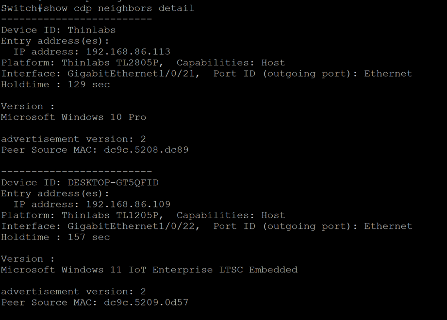
By supporting CDP natively, this allows the switch as well as its administrator to be aware of the devices that are directly connected to it, allowing for faster troubleshooting, provisioning, or auditing.
Integration with Identity Services Engine
Cisco Identity Services Engine (ISE) is a network access control solution. The Catalyst 9300 series of switches work seamlessly with ISE, 802.1X enabled switchports and Cisco Identity Services Engine (ISE) work together to provide a robust network access control solution. ISE can profile PoE devices based on their MAC address, protocols used, and other attributes.
Given the utility and importance of PoE use cases, the topic of security is always at the forefront due to the impact a breach could pose on a PoE solution. Especially for Thinlabs’ use cases, a compromised PoE network would have an immediate impact on the productivity of the users.
For Thinlabs and their customers in regulated industries (e.g., healthcare, finance), the combination of 802.1X and ISE can aid in meeting compliance requirements related to data security and access control. The detailed logging and policy enforcement capabilities provide evidence of secure network practices.
Since Thinlabs support a variety of operating systems, Thinlabs’ devices can utilize many features of ISE to deploy robust security solutions. Some of these features include but are not limited to:
● 802.1x authentication
● Endpoint posture compliance checks
● VLAN placement
● Dynamic access control lists
● Profiling
● Microsegmentation
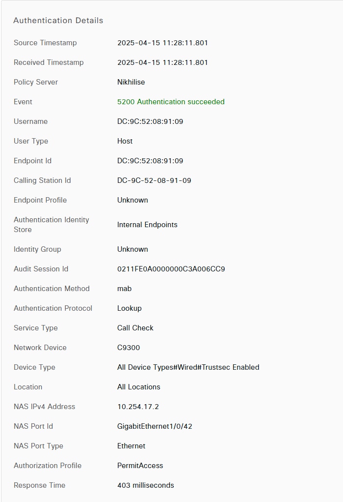
While Power over Ethernet use cases have broadened to include utilities such as lighting and building environmental controls, centralized security solutions such as ISE will play a critical role to ensure that all devices connecting to a network will undergo authentication, authorization, and accounting so that robust outcomes can be achieved without compromise.
A sample output of authentication details on ISE UI for a Thinlabs device connected to the Cisco switch can be seen below.
A sample output of the command “show authentication session interface GigabitEthernet X/X/X details” on the switch CLI is included below.
Access9300#show authentication session interface Gigabit 1/0/42 details
Interface: GigabitEthernet1/0/42
IIF-ID: 0x164E9744
MAC Address: dc9c.5208.9109
IPv6 Address: Unknown
IPv4 Address: Unknown
User-Name: DC-9C-52-08-91-09
Status: Authorized
Domain: DATA
Oper host mode: multi-auth
Oper control dir: both
Session timeout: N/A
Acct update timeout: 172800s (local), Remaining: 172698s
Common Session ID: 0211FE0A0000000F3F9CE43D
Acct Session ID: 0x00000009
Handle: 0xc1000005
Current Policy: Dot1x_MAB
Local Policies:
Service Template: DEFAULT_LINKSEC_POLICY_SHOULD_SECURE (priority 150)
Security Policy: Should Secure
Server Policies:
Method status list:
Method State
dot1x Stopped
mab Authc Success
Note: The outputs above are from very minimal and simple deployments and configurations.
Using ISE in conjunction with the Catalyst 9300 switches opens up a tremendous amount of information that can be gleaned from additional profiling probes sent by ISE to gather additional context about any endpoint. Furthermore, with a managed operating system and dot1x enabled network, Thinlabs’ computers are able to support more stringent protocols in the 802.1x standard for security such as EAP-TLS and MsCHAPv2.
Additional information about Identity Services Engine can be found in the link below:
https://www.cisco.com/site/us/en/products/security/identity-services-engine/index.html
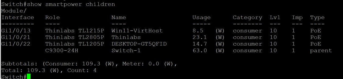
Thinlabs Endpoints with Cisco SmartPower Integration
Cisco SmartPower is an energy management framework developed by Cisco for future-proofed workspaces, where SmartPower provides policy and scheduling framework to reduce energy consumption across a SmartPower domain and its connected devices. The engineering alliance between the two companies led to integrate the framework into Thinlabs products to enable Power Monitoring and Reporting.
In the below picture we can see how the Thinlabs devices are joining a Cisco SmartPower domain and how their energy usage has been reported. This enables visibility and power policing by device type or group of devices.
Outcome of Validations
The following section outlines the outcome of the tests conducted.
Thinlabs Nucleus MiniC in Cisco Smart Buildings Validation
Each Nucleus Mini-PC, the TL1205P and the TL1215P, was connected to the switch (PSE) with a Cat5e ethernet cable.
The lengths of the cable tested were 5m and 100m. The 5m cables were tested to with the intent to minimize power loss and the 100m cables were tested to validate that the PoE solutions could meet the 100m distance specified in the 802.3bt standards.
The 24-inch 1080p monitor, and the TL 2736 27-inch 4K monitor were connected to validate that either monitor can be connected to the Mini-PC to be used as a display for the user.
The diagram above provides a depiction of the solution tested. The Catalyst C9300 has a single home run connected to the Mini-PC.
The Mini-PC then provides power, audio and video data to the display through Thinlabs’ PAV cable.
The keyboard and mouse are connected to the USB 3.0 port on the Mini-PC with a wireless receiver that enables communication between both the devices.
Table 2. Bill of Materials for Nucleus Mini-PC Use Case
| Cisco Product ID |
Description |
Quantity |
| C9300-48H-A |
Cisco Catalyst 9300 switch with 48 UPoE+ interfaces and DNAC Advantage license |
1 |
| PWR-C1-1900WAC-P |
1900-watt power supply for Catalyst 9300 series switch |
1 |
| Thinlabs Product ID |
Description |
Quantity |
| TL1205P |
2-core CPU Mini-PC |
1 |
| TL1215P |
6-core CPU Mini-PC |
1 |
| TLM245 |
Thinlabs 24-inch 1080P PoE monitor |
1 |
| TL2736 |
Thinlabs 27-inch 2160p (4K) PoE monitor |
1 |
| CAB-USBC |
Thinlabs USB-C cable for power, audio, and video |
1 |
A wireless keyboard and mouse were connected, but so long as they meet the USB 2.0 and USB 3.0 standard, peripherals from any manufacturer can realistically be connected to interface with the computer.
Variables Introduced in Tests
The variables introduced in the testing are as follows:
● Length of homerun
◦ 5m or 100m
● Ambient temperature
◦ 60 degrees or 95 degrees F
● Processor state
◦ Idle or stressed with Prime95
● Connected display
◦ TLM245 or TL2736
● Brightness of display
◦ Minimum or maximum
Results Summary of Nucleus Mini-PC Use Case
To summarize the findings of the tests conducted:
● The lowest power draw was 13 watts
◦ Where the 1215P was in an idle state with no load, and the 24-inch display was the dimmest
● The highest power draw was 51 watts
◦ Where the 1205P was stressed with Prime95, and the 27-inch display was brightest
● The length of the cable, whether 5m or 100m, had no influence on the power draw
● The ambient temperature, tested at 65°F and 95°F, had no influence on the power draw
Performance testing demonstrates that Cisco’s UPoE+ switches, compliant with IEEE 802.3bt standards, provide ample power capacity, delivering up to 90 watts per interface, to effectively support the operational requirements of Thinlabs’ PoE-enabled devices.
Detailed Results of Nucleus Mini-PC Use Case
The power draw measured at the interface under the “Actual consumption” section of the output from running “show power inline GigabitEthernet X/X/X detail” are below.
Note: Due to the fluctuations in power draw reading, the numbers displayed below are an average of readouts collected every minute for five minutes. The readouts were collected after allowing the systems to operate for 30 minutes.
The table below displays the results of the tests when connecting the TL1205P Mini-PC to the PSE with a Cat5e 22AWG cable measuring 5m.
Table 3. Power Draw Results from TL1205P with 5m Cat5e 22AWG Homerun
| Ambient Temperature (°F) |
Processor State |
Display Brightness Setting |
Power Draw |
|
| TLM245 |
65 |
Idle |
Minimum |
14.9 |
| Maximum |
21 |
|||
| Prime95 stressed |
Minimum |
23.4 |
||
| Maximum |
34.2 |
|||
| 95 |
Idle |
Minimum |
15.1 |
|
| Maximum |
21 |
|||
| Prime95 stressed |
Minimum |
23.4 |
||
| Maximum |
34.3 |
|||
| TL2736 |
65 |
Idle |
Minimum |
24.4 |
| Maximum |
40 |
|||
| Prime95 stressed |
Minimum |
36.7 |
||
| Maximum |
52.4 |
|||
| 95 |
Idle |
Minimum |
24.1 |
|
| Maximum |
40.4 |
|||
| Prime95 stressed |
Minimum |
36.3 |
||
| Maximum |
51 |
The table below displays the results of the tests when connecting the TL1215P Mini-PC to the PSE with a Cat5e 22AWG cable measuring 5m.
Table 4. Power Draw Results TL1215P with 5m Cat5e 22AWG Homerun
| Ambient Temperature (°F) |
Processor State |
Display Brightness Setting |
Power Draw |
|
| TLM245 |
65 |
Idle |
Minimum |
13 |
| Maximum |
17.8 |
|||
| Prime95 stressed |
Minimum |
23.4 |
||
| Maximum |
28.6 |
|||
| 95 |
Idle |
Minimum |
13 |
|
| Maximum |
18 |
|||
| Prime95 stressed |
Minimum |
23.7 |
||
| Maximum |
28.6 |
|||
| TL2736 |
65 |
Idle |
Minimum |
21.9 |
| Maximum |
34 |
|||
| Prime95 stressed |
Minimum |
32 |
||
| Maximum |
46.7 |
|||
| 95 |
Idle |
Minimum |
22 |
|
| Maximum |
34.2 |
|||
| Prime95 stressed |
Minimum |
31.9 |
||
| Maximum |
46.7 |
The table below displays the results of the tests when connecting the TL1205P Mini-PC to the PSE with a Cat5e 22AWG cable measuring 100m.
Table 5. Power Draw Results TL1205P with 100m Cat5e 22AWG Homerun
| Connected Display |
Ambient Temperature (°F) |
Processor State |
Display Brightness Setting |
Power Draw |
| TLM245 |
65 |
Idle |
Minimum |
15.2 |
| Maximum |
21.4 |
|||
| Prime95 stressed |
Minimum |
23.4 |
||
| Maximum |
34.9 |
|||
| 95 |
Idle |
Minimum |
15.1 |
|
| Maximum |
21.2 |
|||
| Prime95 stressed |
Minimum |
23.4 |
||
| Maximum |
35 |
|||
| TL2736 |
65 |
Idle |
Minimum |
24.4 |
| Maximum |
40 |
|||
| Prime95 stressed |
Minimum |
36.7 |
||
| Maximum |
52.4 |
|||
| 95 |
Idle |
Minimum |
24.5 |
|
| Maximum |
40.1 |
|||
| Prime95 stressed |
Minimum |
36.1 |
||
| Maximum |
51.9 |
The table below displays the results of the tests when connecting the TL1205P Mini-PC to the PSE with a Cat5e 22AWG cable measuring 100m.
Table 6. Power Draw Results TL1215P with 100m Cat5e 22AWG Homerun
| Connected Display |
Ambient Temperature (°F) |
Processor State |
Display Brightness Setting |
Power Draw |
| TLM245 |
65 |
Idle |
Minimum |
13.2 |
| Maximum |
18.4 |
|||
| Prime95 stressed |
Minimum |
23.1 |
||
| Maximum |
28.8 |
|||
| 95 |
Idle |
Minimum |
13.2 |
|
| Maximum |
18.4 |
|||
| Prime95 stressed |
Minimum |
23.1 |
||
| Maximum |
28.9 |
|||
| TL2736 |
65 |
Idle |
Minimum |
22.4 |
| Maximum |
34.2 |
|||
| Prime95 stressed |
Minimum |
32.5 |
||
| Maximum |
46.9 |
|||
| 95 |
Idle |
Minimum |
22.4 |
|
| Maximum |
34 |
|||
| Prime95 stressed |
Minimum |
33 |
||
| Maximum |
47.1 |
Nucleus Mini-PC Use Case Conclusion
The results of the tests show that Cisco’s UPoE+ switches have more than enough capacity to power Thinlabs’ mini-PC’s and provide users with the compute power and connectivity to be productive to meet a wide range of needs. The low power consumption by the mini-PC’s makes a tremendous amount of power available to be used elsewhere such as:
● Connecting more displays in the compute solution
● Substituting parts in computer with higher-performance components
● Distributing wattage to more interfaces on switch
Thinlabs’ mini-PC solutions offer a safer and simpler alternative that reduces time of deployment to the end user. Whereas traditional compute solutions that include an external display would require multiple high voltage alternating current (AC) outlets, Thinlabs’ solution accomplishes the same end goal with a single PoE homerun. The USB-C PAV cable further reduces the cable requirements by combining the functions of both display output and power into a single connection.
Thinlabs All-In-One PC in Cisco Smart Buildings Validation
The TL2805 All-In-One Helios Touchscreen PC was connected to the switch (PSE) with a Cat5e ethernet cable.
The lengths of each cable tested were 5m and 100m. The 5m cables were tested with the intent to minimize power loss and the 100m cables were tested to validate that the PoE compute use case could meet the 100m distance specified in the 802.3bt standards.
The TLM245 24-inch 1080p monitor, and the TL2736 27-inch 4K monitor were connected to validate that either monitor can be connected to the All-In-One PC to be used as a display for the user.
The diagram above provides a depiction of the solution tested. The Catalyst C9300 has a single home run connected to the All-In-One PC.
The All-In-One PC then provides power, audio and video data to the monitor through Thinlabs’ PAV cable.
The keyboard and mouse are connected to the USB 3.0 port on the Mini-PC with a wireless 2.4 GHz receiver that communicates with both devices.
Table 7. Bill of Materials for All-In-One PC Use Case
| Cisco Product ID |
Description |
Quantity |
| C9300-48H-A |
Cisco Catalyst 9300 switch with 48 UPoE+ interfaces and DNAC Advantage license |
1 |
| PWR-C1-1900WAC-P |
1900-watt power supply for Catalyst 9300 series switch |
1 |
| Thinlabs Product ID |
Description |
Quantity |
| TL2805 |
2-core CPU All-In-One PC with 24-inch 1080P display |
1 |
| TLM245 |
Thinlabs 24-inch 1080P PoE monitor |
1 |
| TL2736 |
Thinlabs 27-inch 2160p (4K) PoE monitor |
1 |
| CAB-USBC |
Thinlabs USB-C cable for power, audio, and video |
1 |
A wireless keyboard and mouse were connected, but so long as they meet the USB 2.0 and USB 3.0 standard, peripherals from any manufacturer can realistically be connected to interface with the computer.
Variables Introduced in Tests
The variables introduced in the testing are as follows:
● Length of homerun
◦ 5m or 100m
● Ambient temperature
◦ 60 degrees or 95 degrees F
● Processor state
◦ Idle or stressed with Prime95
● Connected display
◦ TLM245 or TL2736 or no connected display
● Brightness of built-in display
◦ Minimum or maximum
● Brightness of external display
◦ Minimum or maximum
Results Summary of All-In-One PC Use Case
To summarize the findings of the tests conducted:
● The lowest power draw was 23.9 watts
◦ Where the TL2805 was in an idle state with no load, the built-in display was dimmest, and no external display was connected
● The highest power draw was 57.9 watts
◦ Where the TL2805 was stressed with Prime95, the built-in display was brightest, and the connected 27-inch display was brightest
● The length of the cable, whether 5m or 100m, had no influence on the power draw
● The ambient temperature, tested at 65°F and 95°F, had no influence on the power draw
Testing results confirm that the power delivery performance of Cisco’s UPoE+ switches, compliant with IEEE 802.3bt standards, aligns closely with the established use case for the Thinlabs Nucleus Mini-PC. This evaluation focuses on the Thinlabs 1205P Mini-PC configured with both 24-inch and 27-inch displays under maximum load conditions.
All-In-One PC Test Results
In the max load scenario, the 1205P Mini-PC was subjected to intensive computational stress using Prime95, with both the 24-inch and 27-inch displays set to maximum brightness. The power consumption under these conditions remained well within the 90 watts allocated with Cisco UPoE+ connection. The results indicate sufficient residual power capacity to support the addition of another display, if required, without exceeding the power budget.
All-In-One PC Analysis
Consistent with the Nucleus Mini-PC use case, the tests demonstrate that a single UPoE+ connection is all it takes to reliably power and connect the 1205P Mini-PC and multiple displays. The robust power margin ensures scalability, accommodating expanded configurations such as additional displays or peripherals without compromising performance.
All-In-one PC Conclusion
Based on the comprehensive testing conducted, the solution has demonstrably met or exceeded all Cisco smart Building PoE solution requirements for Future-proofed workspaces. Specifically, the Thinlabs 1205P Mini-PC with multiple displays, powered by Cisco UPoE+ switches have demonstrated its operational simplicity, stability, performance, and sustainability aspects even under demanding conditions.
Detailed Results of All-In-One PC Use Case
The power draw measured at the interface under the “Actual consumption” section of the output from running “show power inline GigabitEthernet X/X/X detail” are below.
Note: Due to the fluctuations in power draw reading, the numbers displayed below are an average of readouts collected every minute for five minutes. The readouts were collected after allowing the systems to operate for 30 minutes.
The table below displays the results of the tests when connecting the TL2805 All-In-One PC to the PSE with a Cat5e 22AWG cable measuring 5m.
Table 8. Power Draw Results TL2805 with 5m Cat5e 22AWG Homerun
| Connected Display |
Ambient Temperature (°F) |
Built-In Display Brightness Setting |
Processor State |
External Display Brightness Setting |
Power Draw |
| TLM245 |
65 |
Minimum |
Idle |
Minimum |
30 |
| Maximum |
34.2 |
||||
| Prime95 stressed |
Minimum |
30.8 |
|||
| Maximum |
35.1 |
||||
| Maximum |
Idle |
Minimum |
32.9 |
||
| Maximum |
38.6 |
||||
| Prime95 stressed |
Minimum |
34.4 |
|||
| Maximum |
40 |
||||
| 95 |
Maximum |
Idle |
Minimum |
30.1 |
|
| Maximum |
33.7 |
||||
| Prime95 stressed |
Minimum |
30.7 |
|||
| Maximum |
34.8 |
||||
| Maximum |
Idle |
Minimum |
33.4 |
||
| Maximum |
38.9 |
||||
| Prime95 stressed |
Minimum |
34.3 |
|||
| Maximum |
39.9 |
||||
| TL2736 |
65 |
Minimum |
Idle |
Minimum |
33.9 |
| Maximum |
49.8 |
||||
| Prime95 stressed |
Minimum |
37 |
|||
| Maximum |
53 |
||||
| Maximum |
Idle |
Minimum |
36.6 |
||
| Maximum |
53.2 |
||||
| Prime95 stressed |
Minimum |
41.7 |
|||
| Maximum |
57.4 |
||||
| 95 |
Maximum |
Idle |
Minimum |
34 |
|
| Maximum |
50.2 |
||||
| Prime95 stressed |
Minimum |
36.9 |
|||
| Maximum |
53.1 |
||||
| Maximum |
Idle |
Minimum |
36.8 |
||
| Maximum |
53 |
||||
| Prime95 stressed |
Minimum |
41.8 |
|||
| Maximum |
57.4 |
The table below displays the results of the tests when connecting the TL2805 All-In-One PC to the PSE with a Cat5e 22AWG cable measuring 100m.
Table 9. Power Draw Results TL2805 with 100m Cat5e 22AWG Homerun
| Connected Display |
Ambient Temperature (°F) |
Built-In Display Brightness Setting |
Processor State |
External Display Brightness Setting |
Power Draw |
| TLM245 |
65 |
Minimum |
Idle |
Minimum |
30.2 |
| Maximum |
34 |
||||
| Prime95 stressed |
Minimum |
30.8 |
|||
| Maximum |
35.1 |
||||
| Maximum |
Idle |
Minimum |
33.7 |
||
| Maximum |
38.7 |
||||
| Prime95 stressed |
Minimum |
34.3 |
|||
| Maximum |
39.4 |
||||
| 95 |
Maximum |
Idle |
Minimum |
30.1 |
|
| Maximum |
34 |
||||
| Prime95 stressed |
Minimum |
31.1 |
|||
| Maximum |
35 |
||||
| Maximum |
Idle |
Minimum |
33.7 |
||
| Maximum |
38.8 |
||||
| Prime95 stressed |
Minimum |
34.4 |
|||
| Maximum |
39.4 |
||||
| TL2736 |
65 |
Minimum |
Idle |
Minimum |
33.9 |
| Maximum |
50 |
||||
| Prime95 stressed |
Minimum |
37 |
|||
| Maximum |
52.7 |
||||
| Maximum |
Idle |
Minimum |
36.6 |
||
| Maximum |
53.2 |
||||
| Prime95 stressed |
Minimum |
41.7 |
|||
| Maximum |
57.9 |
||||
| 95 |
Maximum |
Idle |
Minimum |
33.9 |
|
| Maximum |
50.2 |
||||
| Prime95 stressed |
Minimum |
37 |
|||
| Maximum |
52.7 |
||||
| Maximum |
Idle |
Minimum |
36.6 |
||
| Maximum |
53.2 |
||||
| Prime95 stressed |
Minimum |
41.4 |
|||
| Maximum |
57.9 |
The table below displays the results of the tests when connecting the TL2805 All-In-One PC to the PSE with a Cat5e 22AWG cable measuring 5m, but with no external display connected.
Table 10. Power Draw Results TL2805 with 5m Cat5e 22AWG Homerun, without external display
| Ambient Temperature (°F) |
Processor State |
Built-In Display Brightness Setting |
Power Draw |
| 65 |
Idle |
Minimum |
23.9 |
| Maximum |
28 |
||
| Prime95 stressed |
Minimum |
24.5 |
|
| Maximum |
28.7 |
||
| 95 |
Idle |
Minimum |
24 |
| Maximum |
28 |
||
| Prime95 stressed |
Minimum |
25.1 |
|
| Maximum |
29 |
The table below displays the results of the tests when connecting the TL2805 All-In-One PC to the PSE with a Cat5e 22AWG cable measuring 5m, but with no external display connected.
Table 11. Power Draw Results TL2805 with 100m Cat5e 22AWG Homerun, without external display
| Ambient Temperature (°F) |
Processor State |
Built-In Display Brightness Setting |
Power Draw |
| 65 |
Idle |
Minimum |
24 |
| Maximum |
28 |
||
| Prime95 stressed |
Minimum |
24.4 |
|
| Maximum |
28.7 |
||
| 95 |
Idle |
Minimum |
24.1 |
| Maximum |
28.2 |
||
| Prime95 stressed |
Minimum |
24.5 |
|
| Maximum |
28.8 |
Technical Evaluation
Power Delivery Performance of Cisco UPoE+ Switches for Thinlabs All-In-One PC and Nucleus Mini-PC
Testing conducted on the integration of Cisco UPoE+ Catalyst switches with Thinlabs’ Nucleus Mini-PC and All-In-One PC validates the consistent power delivery and data connectivity capabilities under various operating conditions. The Cisco UPoE+ switch, adhering to IEEE 802.3bt standards, consistently provided sufficient power to operate the All-In-One PC, an external 27-inch display, and associated peripherals, aligning with performance expectations established by the Nucleus Mini-PC.
Test Results
Under maximum load conditions, which included setting both the integrated display and the 27-inch external display to peak brightness and subjecting the system to intensive computational stress using Prime95, the total power consumption reached a maximum of 57.9 watts. This value is well within the 90-watt capacity per interface of the Cisco UPoE+ switch, indicating a substantial power margin for additional components or peripherals.
Power Budget Flexibility
The significant unused power capacity allows for scalability in system configurations. Users can incorporate additional displays or higher-performance components without exceeding the power budget. Furthermore, the Cisco UPoE+ switch supports dynamic power reallocation, enabling unutilized wattage from one interface to be redistributed to other interfaces, thereby optimizing power delivery across connected devices.
Simplified System Architecture
In scenarios requiring a single display, the All-In-One PC streamlines deployment by integrating compute components directly into the display, eliminating the need for a USB-C Power and Video (PAV) cable. For multi-display configurations, additional monitors can be seamlessly connected to the All-In-One PC via USB-C PAV cables, reducing cabling complexity compared to traditional setups requiring separate power and display cables.
Technical Evaluation Conclusion
The Cisco UPoE+ switch and smart buildings feature integrations such as CDP, ISE demonstrates robust and efficient power delivery for Thinlabs’ All-In-One PC and Nucleus Mini-PC, supporting demanding workloads while maintaining flexibility for expanded configurations. The ability to reallocate power dynamically and simplify cabling enhances the scalability and practicality of this PoE-based computing solution.
Efficacy and Sustainability of Thinlabs and Cisco Computing Solutions
Testing has substantiated that Thinlabs’ Power over Ethernet (PoE) compute and display solutions, integrated with Cisco’s UPoE+ switches, provide a robust and efficient alternative to conventional high-voltage computing infrastructure. This collaboration, facilitated through Cisco’s Engineering Alliance, leverages IEEE 802.3bt-compliant PoE technology to deliver power and data over a single Ethernet cable, significantly enhancing deployment flexibility and sustainability.
Reduction in Material and Infrastructure Requirements
The adoption of PoE eliminates the need for extensive high-voltage cabling and conduit installations, resulting in a substantial reduction in material usage. Thinlabs’ computers require only a single PoE connection to the PSE for power and data, with display connectivity achieved via USB-C Power and Video (PAV) cables. This minimalist cabling architecture simplifies deployment and reduces the environmental footprint associated with infrastructure development.
Enhanced Resiliency and Simplified Maintenance
PoE-based systems streamline resiliency measures by centralizing power management at the PSE. Implementing uninterruptible power supply (UPS) solutions at the switch level ensures continuous operation of connected compute devices during power disruptions, eliminating the need for individual AC power backups. This centralized approach enhances system reliability and reduces the complexity and cost of maintaining resiliency across distributed endpoints.
Integration with Cisco Discovery Protocol (CDP)
Thinlabs’ devices are fully compatible with the Cisco Discovery Protocol (CDP), enabling seamless integration with Cisco’s PoE infrastructure. CDP facilitates optimized power allocation by allowing the PSE to dynamically negotiate power requirements with Thinlabs’ devices, ensuring efficient energy use. Additionally, CDP supports Real-Time Transport Protocol (RTP) for streamlined device configuration and provides diagnostic capabilities enhancing system reliability and simplifying troubleshooting. This compatibility maximizes the efficiency and manageability of the PoE ecosystem, reinforcing the robustness of the Thinlabs-Cisco solution.
Contribution to Sustainability Goals
The partnership between Thinlabs and the Cisco Engineering Alliance advances Power over Ethernet (PoE) technology to support global net-zero utility consumption goals by delivering energy-efficient computing solutions. By integrating Thinlabs’ low-power PoE computers and displays with Cisco’s high-efficiency PoE switches and smart buildings framework, the collaboration reduces electrical demand, simplifies infrastructure, and enhances deployment flexibility. These scalable and resilient solutions meet diverse computing needs while minimizing ecological impact, aligning with sustainability initiatives and providing measurable benefits for organizations seeking operational efficiency and future-proofed, environmentally responsible Cisco workspaces.