Cisco and MHT Implementation Guide
Available Languages
Bias-Free Language
The documentation set for this product strives to use bias-free language. For the purposes of this documentation set, bias-free is defined as language that does not imply discrimination based on age, disability, gender, racial identity, ethnic identity, sexual orientation, socioeconomic status, and intersectionality. Exceptions may be present in the documentation due to language that is hardcoded in the user interfaces of the product software, language used based on RFP documentation, or language that is used by a referenced third-party product. Learn more about how Cisco is using Inclusive Language.
- US/Canada 800-553-2447
- Worldwide Support Phone Numbers
- All Tools
 Feedback
 Feedback
Purpose and Overview
Overview
MHT, a leader in innovative lighting solutions with its MHT Technologies portfolio, has partnered with Cisco’s Engineering Alliance to deliver cutting-edge smart building solutions, leveraging Cisco’s future-proofed workspaces framework and related features developed by Cisco. This collaboration integrates power and data delivery over a single Ethernet cable, enabling efficient, scalable, and future-ready building management systems. By combining MHT’s Inspextor hardware portfolio, including MHT Technologies, with Cisco’s PoE switches, this solution transforms traditional building systems into intelligent, energy-efficient ecosystems.
Power over Ethernet Advancements
The IEEE 802.3bt standard has significantly expanded PoE capabilities beyond its original applications, such as powering wireless access points and IP phones. Cisco’s Universal Power over Ethernet Plus (UPoE+) capable switches deliver up to 90 watts of power per port, enabling a wide range of devices to be powered and controlled over Ethernet infrastructure. This advancement supports innovative use cases, including advanced lighting systems, automated shades, height-adjustable desks, and PoE-powered displays.
Benefits of PoE Solutions
Ability to deliver data and Power over Ethernet offers a flexible, safe, and energy-efficient alternative to traditional high-voltage systems. Key advantages include:
● Energy Efficiency
PoE's inherent design allows for dynamic power allocation, ensuring that devices only utilize energy during operation, which contrasts with the static and potentially wasteful power delivery of traditional high-voltage systems.
● Simplified Infrastructure
A single Ethernet cable delivers both power and data, reducing installation complexity and costs.
● Sustainability
Simplified PoE solutions eliminate a tremendous amount of steel conduits which is a standard for line voltage cabling thus reducing carbon footprint and contributing to net-zero energy goals by further optimizing power consumption and minimizing electrical circuit demands.
● Safety
By employing low-voltage DC power delivery, PoE mitigates many of the electrical safety risks inherent in high-voltage installations.
Architecture Validation and Use Cases
● Lighting
Intelligent, PoE-powered lighting systems, featuring MHT Technologies, for dynamic control and energy savings.
● Automated Shades
Motorized shading systems integrated with building automation for optimized light and temperature management.
● Height-Adjustable Electronic Desks
Ergonomic workstations powered and controlled via PoE for flexible office environments.
● PoE-Powered Displays
Digital signage and monitors by PoE for streamlined deployment and maintenance.
Target Audience
● Project and account managers
● Mechanical, electrical, and plumbing (MEP) engineers and partners
● System integrators
● Installers
● Supply chain vendors
Introduction Summary
The collaboration between MHT and Cisco leverages enhanced PoE technologies to deliver scalable, efficient, and resilient smart building solutions. By integrating MHT’s Inspextor hardware with Cisco’s UPoE+ switching infrastructure and their unique features, this partnership enables organizations to modernize building systems, reduce energy footprint, and achieve operational and user experiences while nurturing healthy and productive workforces.
Components Used for Validations
The components detailed in this section were specifically chosen from the extensive MHT PoE and Cisco UPoE+ switching product lines to validate the presented use cases. It should be understood that this is a small subset of the available products and only represents what was used for this feasibility study.
MHT Inspextor Components
The following section will outline the individual components manufactured by MHT. It is important to note that the devices referenced below are considered first-party products with MHT product identifiers (PID) and stock keeping unit (SKU).
Aida Management Software
Formerly known as Inspextor, Aida is the software that manages the MHT’s PoE solution. Aida can be deployed on a physical appliance, or a virtual machine, and the hardware requirements are as follows:
● CPU: 2 cores with a minimum clock speed of 2.5 GHz
● Memory: 4 GB of RAM
● Storage: 350 GB of hard disk
The software package is installed on an Ubuntu Linux version 20.04 LTS operating system.
The Linux machine requires connectivity to the internet as well as layer 2, internal connectivity to the nodes which Aida will be managing. The required ports to communicate on the network with Aida are as follows:
● 22, secure shell (SSH)
◦ For remote console access to Aida
● 69, trivial file transfer protocol (TFTP)
◦ For transferring files to and from Aida
● 80, hypertext transfer protocol (HTTP)
◦ For browser access to Aida
● 5683, Constrained Application Protocol (COAP)
◦ To communicate with all devices encompassing the PoE solution
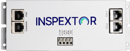
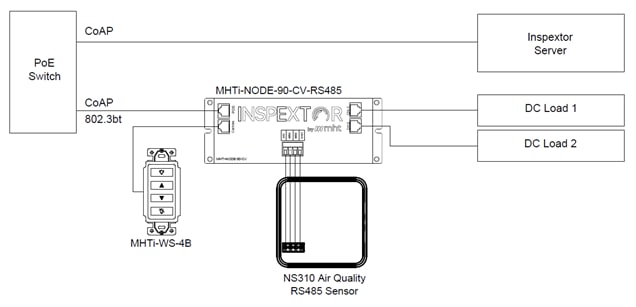
MHTi-NODE-90
The MHTi-NODE-90 (node) is the workhorse of MHT’s PoE solutions. It connects to the PoE switch with an Ethernet cable (more on this later in this document) and then powers downstream devices, allocating power according to MHT’s management software or its default configuration. The nodes are available in a variety of configurations to meet the needs of the solutions such as constant current and/or voltage, various maximum current values based on voltage, and presence of a springe cage connector with their own variety of specifications.
The spring cage connector allows for communications with third-party end devices that may not fall under the MHT Inspextor PoE portfolio, such as an NS310 air quality sensor, or an NS311 occupancy sensor. Allowing additional devices to connect to the PoE network via the spring cage connector enables a variety of capabilities such as collecting data from sensors to act on said data or delivering power to end devices that do not interface with ethernet cables as MHT devices do.
In the validations conducted, the nodes primarily acted as the method to deliver the direct current (DC) power from the Catalyst 9300 switch to the devices connected to achieve the desired outcome.
Additional information regarding the MHTi-NODE-90 can be found on MHT’s product page in the link below.
https://mht-technologies.com/wp-content/uploads/2024/11/MHT-NODE-90-Consolidated-v2.pdf
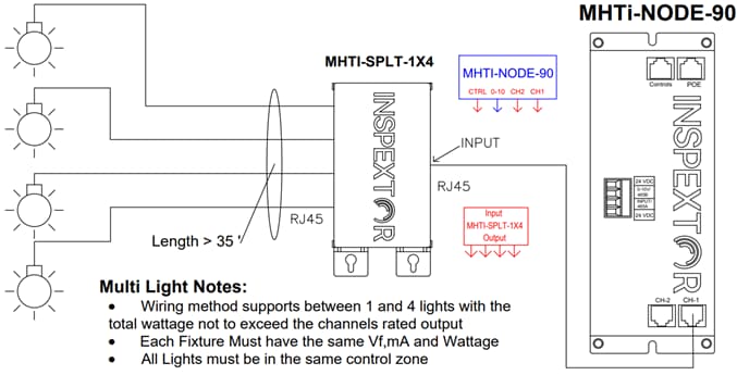
PoE Splitter Box
The PoE splitter box allows for multiple end devices to be connected to any interface on a node except for the PoE interface. This allows for flexibility in PoE solutions by effectively utilizing the node to its full potential by acting as a mechanism to connect as many devices as the node will allow.
By connecting the splitter box to the control interface, the control mechanisms can be distributed to multiple devices such as wall switches, or sensors that can trigger actions such as moving automated shades and adjusting the brightness and color temperature of a space. The illustrations below are taken from the product page for the splitter box published by MHT, which will have a link at the end of this section.
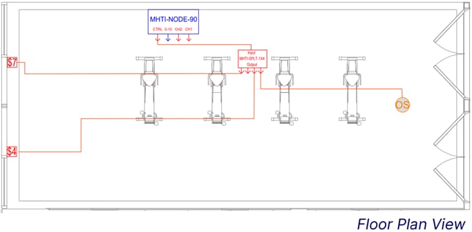
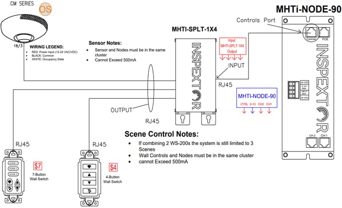
The splitter box can also be connected to a power output channel to distribute the power available to each channel. The illustrations below are taken from the product page for the splitter box published by MHT, which will have a link at the end of this section.

Top View
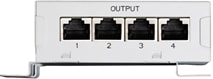
Output-Side View
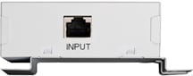
Input-Side View
In the validations conducted, the splitter box was used to connect as many devices as possible to the output channels to maximize the power draw from the node.
Additional information regarding the PoE Splitter Box can be found on MHT’s product page in the link below.
https://mht-technologies.com/wp-content/uploads/2024/02/MHTi-SPLT-1X4-Spec-Sheet.pdf
Wall Switch
The MHTi-WS wall switch allows users to control PoE-powered devices according to their preferences or settings. For example, in lighting applications, it enables them to increase or decrease the power to adjust fixture brightness.
In some use cases, such as with automated shades, it is not simply a matter of increasing or decreasing the power draw but also sending data to the devices downstream from the node. For PoE shades solutions, the node will respond to inputs from the wall switch by:
● providing power to the motors so that they will move
● instructing the motors to turn in the desired direction to move the shades to achieve the desired outcome
Devices such as the wall switch afford users the agency to fine tune PoE solutions, thereby enabling customization to address individual needs that may not be fully satisfied by default or pre-set configurations.
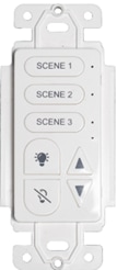
To provide the user with flexibility, MHT wall switches comes in two different configurations:
● 4-button with the following buttons:
◦ On
◦ Up
◦ Down
◦ Off
● 7-button with the following buttons:
◦ Scene 1
◦ Scene 2
◦ Scene 3
◦ On
◦ Up
◦ Down
◦ Off
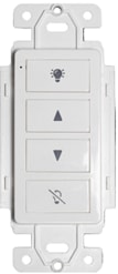
When testing the lighting use case, the four-button wall switch was used and the “off” button was programmed to turn the fixtures off.
The “on” button would restore the last state of the output channels prior to being turned off. As an example, if the light fixtures were at 70% brightness and they were turned off, pressing the “on” button restored them back to the same brightness.
The “up” and “down” buttons were programmed to provide incremental controls to the lights where the “up” and “down” buttons increased or decreased the brightness respectively.
In the automated shades use case, the “off” button lowered the shades to the bottom-most position, and the “on” button raised the shades to the top-most position. The “up” and “down” buttons moved the shades in the corresponding direction.
On the 7-button switch, each “scene” button can be programmed to a preset configuration so that the desired outcome can be achieved with a single button press rather than pressing “up” and “down” buttons incrementally until it reaches the same outcome.
It is important to note that the buttons on all the switches can be programmed to achieve different outcomes than the ones that intuitively come to mind. As an example in the automated shades use case, the four-button wall switch can be programmed in the following manner to move the shades in predetermined positions, rather than incremental control:
● “On” button moves the shades to top-most position
● “Up” button moves the shades to 1/3 way down
● “Down” button moves the shades to 2/3 way down
● “Off” button moves the shades to bottom-most position
The administrator can manipulate the outcome of the wall switch inputs as desired or needed.
Additional information regarding the various wall switches can be found on MHT’s product page in the link below.
https://mht-technologies.com/wp-content/uploads/2024/02/MHTi-WS-Spec-Sheet.pdf
MHTi-RJM/RJF
MHT manufactures cables to connect their nodes to all manner of devices to operate on DC power. RJ45 connectors are manufactured in a variety of configurations that include but are not limited to:
● Male vs Female connector
● Straight vs Right-angle connector
● 1 to 8 wire cables
● RJ45 to DC barrel plug
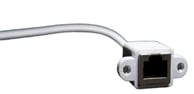
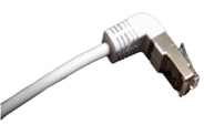
Providing a variety of cable terminations enables Aida and the nodes to interface with a tremendous number of DC devices that fall outside of MHT’s portfolio. As an example, one of the use cases which required such a cable was powering an external monitor with a node. A 27-inch 4K monitor was powered via PoE by connecting the monitor to a node using a cable with an RJ45 connector on the end that connected to the node, and a DC barrel plug that was inserted into the monitor.
This flexibility of terminating cables with different connectors allows MHT to deliver DC power to any device that can connect to the node.
Additional information regarding the RJ45 terminations can be found on MHT’s product page in the link below.
https://mht-technologies.com/wp-content/uploads/2024/02/MHT-RJF_RJM-Spec-Sheet-1.pdf
MHTi-SMD-KIT – Smart Desk Kit
The MHT Smart Desk Kit is a bundle that can be purchased with the elements desired to deploy in a height-adjustable desk solution. The product identification numbers and their descriptions as listed by MHT are below:
● MHTi-SMD-INT-L
◦ Smart Desk Sensor Interface Linak
● MHTi-NODE-90-CV-USBC-8
◦ RW from 90W CV RS485 Rev8 to USBC
● MHTi-NODE-90-CV-RS485-8
◦ 90W Constant Voltage with RS485-Rev8
● MHTi-LINAK-CAB0965388-1800
◦ 6 FT DC Cable for D2D
● MHTi-CAT5-6FT-PC-B
◦ Case5e Ethernet Cable – 6 ft – Black – Patch Cable – Molded Cat5e Cable – Short Network Cable -Ethernet Cord – Cat 5e Cable – 6ft (M45PATCH6BK)
● MHTi-LINAK-CHUSBC2A1-000
◦ Desk2Device – USB-C Charger
● MHTi-RJM-2Wire-5.5-2.5mm-P
◦ RJ45 male to DC Power jack male 5.5-2.5mm (Task Light)
● MHTi-RJ45-DC-P
◦ Silicone 110Pcs Ethernet Hub Port RJ45 Anti-Dust Cover Plugs Protector Stopper Cap for Female Port Black for TV, Computer, Other Devices
● MHTi-1.5ft-MRJ45-MRJ45-90
◦ Cat5 Ethernet Cable, RJ45 Male to Male 90 Degree Internet Network LAN Cable Patch Cord
● MHTi-LINAK-1018w1218-A
◦ Mounting Adhesive
● MHTi-PoE-Cradle_TrayKit
◦ Cradle/Tray Kit (no electrics)
● MHTi-RJM90-2PMF-DC
◦ RJM90 to 2wire mini fit Jr. plug
● MHTi-INSP-NODE
◦ Inspextor Software – Per Node Charge
Below is a sample PoE height adjustable desk solution diagram that can be found on MHT’s Smart Desk Interface product page.
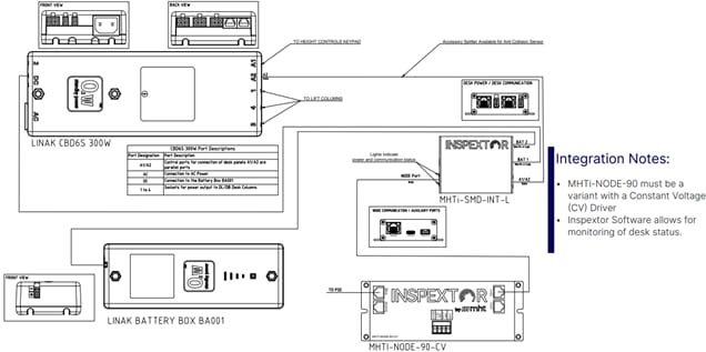
Additional information regarding the MHT Smart Desk Interface can be found on their product in the link below.
https://mht-technologies.com/wp-content/uploads/2024/07/MHT-SMD-INT-Spec-Sheet_V2_7.14.24-2.pdf
Cisco Components
The following section will outline the individual components manufactured by Cisco. It is important to note that the devices referenced below are considered first-party products with Cisco product identifiers (PID) and stock keeping unit (SKU).
Cisco Catalyst 9300
The Catalyst C9300-48H-A was provisioned for this validation because of the UPoE+ capabilities of the switch. This will allow the MHT node to display its full potential by being permitted to negotiate for the full power outlined in the 802.3bt standards.
Additional information regarding the Cisco Catalyst 9300 portfolio of switches can be found on Cisco’s switch datasheet in the link below.
The switch will be running software version Cisco IOS XE 17.15.2, for which the release notes can be found in the link below:
Power Supply
The selection of a power supply unit for the Catalyst 9300 is primarily governed by the aggregate power budget necessitated by the Power over Ethernet (PoE) solution/endpoints. The power supplies for Cisco Catalyst 9300 switches are available in both Alternating Current (AC) and Direct Current (DC) input configurations, with a spectrum of wattage ratings offered within the AC models.
It is important to note that the power supplies will always budget a certain portion of the total power available to power the switch hardware and software components, while the remainder will be made allocated to PoE budget that can be distributed to the PoE endpoints. The system power demands will be predicated by the model of the Catalyst 9300.
Additional information regarding the power supplies for the Catalyst 9300 portfolio of switches can be found on Cisco’s datasheet in the link below:
Power Budget Calculation
In the Catalyst 9300 datasheet linked above, table 4 provides the power available for PoE with the matching power supply configuration. In designing the PoE based power delivery architecture, some of the factors to consider when selecting the switch model and power supplies are:
● How many switch interfaces will be providing PoE power?
● What is the PoE class for each PoE endpoint?
● What is the total power requirement for all connected devices, including the Catalyst switch itself and the PoE-powered solutions to achieve the desired outcome?
● What is the highest power that the PoE solution can draw in a normal and max loads?
● How will the total available power be distributed to each interface based on PoE endpoint class?
● How many switches will be required to meet the total power requirement?
● Is redundancy required?
● Is the system scalable for immediate future needs?
Including the factors above, there are applicable building regulations, standards, and code that will influence the overall system design. Designing the PoE network will require strong collaboration to ensure that the DC PoE power can be effectively distributed to realize maximum value and achieve optimal efficiency, while remaining compliant with all the required regulations to operate safely.
Cabling Components
The following section outlines the cables used in conducting the validations for this document.
22AWG Cat5e Ethernet Cables
Based on the 802.3bt standards, many cable manufacturers have made ethernet cables optimized for PoE power delivery with thicker 22AWG cables that can minimize power loss over the length of the connection. In this setup we tested with two cat5e cables measured 5 meters and 100 meters in length. The 5 meters was used to demonstrate a shorter homerun that would experience near zero power loss, while 100 meters was used to demonstrate viability of a home run at the maximum length governed by the 802.3bt standards.
23AWG Cat6 Ethernet Cables
To reflect the more commonplace brownfield deployments of existing network infrastructures, Cat6 cables were also chosen to validate the use cases. These tests aimed to verify that these pre-existing infrastructures could deliver the power necessary to enable UPoE+ use cases, thus avoiding the need for entirely new cabling. As with the Cat5e cables, two Cat6 cables, one 5 meters long and another 100 meters long, were used in conducting these tests.
Reference Architecture
This section will outline the reference architecture used to conduct the testing.
High-Level Diagram of PoE Network
There are components that are fundamentally required in all the tests. Being that they’re required, the components present in all of them are:
● Aida, PoE solution management software
A virtual machine was deployed in a hypervisor that was installed to a Cisco UCS C220 M6 server with the hardware specifications below:
◦ 4 vCPU
◦ 16 GB of RAM
◦ 200 GB of thin provisioned hard disk space
● Power Sourcing Equipment (PSE), the Cisco Catalyst C9300-48H in this case
● An MHTi-NODE-90 node
A diagram of the shared connectivity architecture is represented below, with the node enlarged in scale to represent the homerun connection back to the PSE from the PoE interface on the node.
Note: Due care is strongly recommended when connecting the node to the switch. The newest revisions of the nodes are intelligent enough to prevent damage, but older revisions may not be and connecting the switch to the wrong interface will cause damage to the node.
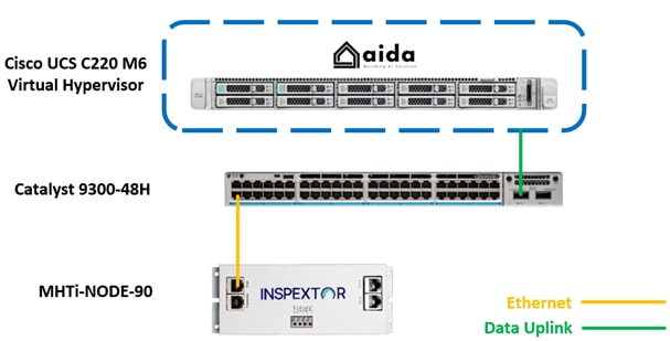
The data uplink connection in the diagram above between Hypervisor and network switch can be either a copper or fiber connection. The physical medium of connecting Aida to the network is irrelevant because the only requirement for Aida to manage the nodes is to be in the same network they are to communicate over layer 2.
Validation Methodology
Functional Operation
To validate the functional operation, the desired outcomes for the listed use cases are as follows:
● Lighting
◦ The square downlights connected to the power output interfaces are all able to be turned on
◦ The wall switch connected to the controls interface will be able to adjust the brightness
● Automated Shades
◦ The two motors connected to the node will operate to move the shades up and down the window
◦ The wall switch connected to the controls interface will be able to move the shades up, down, and stop as intended
● Height Adjustable Desks
◦ The battery can be charged by the PoE solution to provide sufficient power to the legs to adjust the height of the tabletop with a load of 300 pounds
◦ The intent of this solution is not for the node to directly run the motor to adjust the height, bur rather to charge the battery that powers the motor during operations
● External Display
◦ The 27-inch 4K monitor powered by PoE will turn on and operate across minimum and maximum brightness
If every use case yields the desired outcome, it will be considered as a successful validation.
Catalyst 9300 Switch PSE Operational State
For simplicity, the Catalyst 9300 switch command line interface will be used to confirm that the switch is allocating and delivering the required power to the MHT solution under the 802.3bt standards. There are several commands where the outputs can verify the switch is allocating enough power to run its own systems as well as deliver power to the connected PoE endpoints, however the command “show power inline GigabitEthernet X/X/X detail” provides the near real-time power draw on the interface connected to the PoE computer that will provide the most conclusive evidence sought after in these tests.
Here are some insights the following command output provides:
● PoE Configuration and Status
● Power Allocation and Consumption
● Power Negotiation
● PoE Capabilities and Features
● PoE interface Counters and Statistics
These outputs will provide tremendous value when confirming actual power draw and helps to effectively design and operate the PoE infrastructure effectively.
A sample of the output of the command is shown below:
Access9300#show power inline gigabitEthernet 1/0/21 detail
Interface: Gi1/0/21
Inline Power Mode: auto
Operational status (Alt-A,B): on,on
Device Detected: yes
Device Type: Ieee PD
Connection Check: SS
IEEE Class (Alt-A,B): 8
Physical Assigned Class (Alt-A,B): 8
Discovery mechanism used/configured: Ieee and Cisco
Police: off
Power Allocated
Admin Value: 90.0
Power drawn from the source: 90.0
Power available to the device: 90.0
Allocated Power (Alt-A,B): 90.0
Actual consumption
Measured at the port(watts) (Alt-A,B): 18.3
Maximum Power drawn by the device since powered on: 22.5
Absent Counter: 0
Over Current Counter: 0
Short Current Counter: 0
Invalid Signature Counter: 0
Power Denied Counter: 0
Power Negotiation Used: IEEE 802.3bt LLDP
LLDP Power Negotiation --Sent to PD-- --Rcvd from PD--
Power Type: Type 2 PSE Type 2 PD
Power Source: Primary PSE
Power Priority: high low
PD 4PID: 0 0
Requested Power(W): 71.3 71.3
Allocated Power(W): 71.3 71.3
Requested Power ModeA(W): 0.0 0.0
Allocated Power ModeA(W): 0.0 0.0
Requested Power ModeB(W): 0.0 0.0
Allocated Power ModeB(W): 0.0 0.0
PSE Powering Status: 4 pair SS PD Ignore
PD Powering Status: Ignore SS PD
PSE Power Pair ext: Both Alternatives Ignore
DS Class Mode A ext: SS PD Ignore
DS Class Mode B ext: SS PD Ignore
SS Class ext: Class 8 Class 8
PSE Type ext: Type 4 PSE Type 4 SS PD
PSE Max Avail Power: 71.3 0.0
PSE Auto Class Supp: No No
PD Auto Class Req: No No
PD Power Down Req: No No
PD Power Down Time(sec): 0 0
Four-Pair PoE Supported: Yes
Spare Pair Power Enabled: Yes
Four-Pair PD Architecture: Shared
Perpetual POE Enabled: TRUE
Fast POE Enabled: TRUE
The output shown above confirms that the switch is successfully negotiating with the node to allocate the desired power for PoE as well as actual power draw at the time the command was executed.
Additional information regarding the commands for software version 17.15.2 can be found at:
Catalyst 9300
This section provides implemented configurations on the switch.
Global Configurations
Global configuration on a Cisco switch refers to the mode in which you can configure settings that apply to the entire switch, rather than just a specific interface or feature.
This section will provide the recommended configurations at the global level of the switch.
Step 1. Configure a VLAN for PoE network
configure terminal
vlan 15
description MHT PoE network
Step 2. Configure interface Vlan/SVI
configure terminal
interface vlan 15
description MHT Networks
ip address 10.254.17.17 255.255.255.240
Step 3. Enable lldp
configure terminal
lldp run
Step 4. Enable CDP
CDP provides similar basic PoE power negotiation and dynamic updates as LLDP.
configure terminal
cdp run
The aforementioned configurations placed the MHT devices in Vlan 15 with a 10.254.17.16/28 IP network. The configurations documented here are essentials for the MHT device to operate with power and data connectivity, other configurations such as high availability, security can be added based on the overall network design.
For the nodes to communicate with Aida, they must be assigned IP addresses. In this validation, per-port IP address assignment was used where the switch acted as the DHCP server and any device that connected to a configured interface is set to receive the same IP.
Step 5. Configure IP DHCP Scope
configure terminal
ip dhcp pool MHT_Lights
network 10.254.17.16 255.255.255.240
address 10.254.17.20 client-id "Gi1/0/2" ascii
address 10.254.17.21 client-id "Gi1/0/3" ascii
address 10.254.17.22 client-id "Gi1/0/4" ascii
address 10.254.17.23 client-id "Gi1/0/5" ascii
Step 6. Configure interfaces to user parameters configured in DHCP pool
configure terminal
interface range GigbitEthernet 1/0/2-5
switchport mode access
switchport access vlan 15
ip dhcp server use subscriber-id client-id
LLDP Considerations
It is imperative that lldp is running and operational so that a node connecting to the switch can negotiate for all 90 watts to be allocated to the connected interface.
To validate that negotiations are successful, an administrator can run “show lldp neighbor GigabitEthernet X/X/X detail” for the desired interface.
A sample output for the command after successful negotiations can be found below.
Access9300#show lldp neighbors gig 1/0/37 detail
------------------------------------------------
Local Intf: Gi1/0/37
Chassis id: fc0f.e7c1.eab7
Port id: POE PD
Port Description: inspeXtor
System Name - not advertised
System Description:
sysDescr.0 = STRING: <<Port_Desc: inspeXtor; HW_REV: Rev 120219.0; VENDOR: inspeXtor; SERIAL_NUM: 32670; MODEL: 90-watt; FW_REV: Rev 120219.0>>
Time remaining: 108 seconds
System Capabilities - not advertised
Enabled Capabilities - not advertised
Management Addresses:
IP: 10.254.17.26
Auto Negotiation - supported, enabled
Physical media capabilities:
1000baseT(FD)
100base-TX(FD)
100base-TX(HD)
10base-T(FD)
10base-T(HD)
Media Attachment Unit type: 1
Vlan ID: - not advertised
Peer Source MAC: fc0f.e7c1.eab7
UPOE/UPOE+ Power-via-MDI TLV:
Power Pair: Ignore
Power Class: Class 8
Power Device Type: Type 4 SS PD
Power Source: PSE
Power Priority: low
Power Requested: 71300 mW
Power Allocated: 71300 mW
MED Information:
MED Codes:
(NP) Network Policy, (LI) Location Identification
(PS) Power Source Entity, (PD) Power Device
(IN) Inventory
H/W revision: Rev 120
F/W revision: Rev 120
S/W revision: Rev 120
Serial number: 32670
Manufacturer: inspeXtor
Model: 90-watt
Asset id: V1234
Capabilities: PD
Device type: Network connectivity
Network Policies - not advertised
PD device, Power source: PSE, Power Priority: Critical, Wattage: 25.5
Location - not advertised
Total entries displayed: 1
Cisco Recommended Switch Features to Consider
Cisco’s Catalyst 9300 switches have features developed for Smart Buildings and POE specific use cases. especially PoE specific features that can optimize and enhance PoE solutions. This section will outline a few of these features.
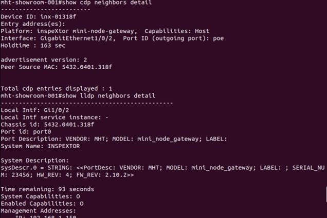
Cisco Discovery Protocol
Under the alliance MHT PoE nodes are now equipped with Cisco proprietary CDP (Cisco Discovery Protocol). CDP automatically discovers and shares information about other directly connected CDP capable devices. This simplifies network setup and management as there is no need to manually configure neighboring devices. Once a CDP capable device is powered on, it automatically starts sending CDP packets out of every active interface, this has enhanced MHT devices to inform their connected cisco catalyst switches about the manufacturer, computer model, IP, MAC address, and version.
A sample of the output “show cdp neighbor gigabitEthernet X/X/X detail” can be found below:
StackPower
Cisco StackPower, a key feature of the Catalyst 9300 series, enables the aggregation of power from the operating power supplies of up to four stacked switches into a unified, larger power pool. This aggregated resource provides redundancy, ensuring that a switch and its connected PoE devices remain operational despite a catastrophic power supply failure within the stack.
In the absence of StackPower, a failed power supply may drastically reduce the available PoE power.
For example, if a standalone Catalyst C9300-48H switch has two 1,100-watt power supplies, it will have 1,922 watts available for PoE power. If the switch is deployed in a PoE lighting solution where 15 interfaces are using 90 watts, the solution requires 1,350 watts for PoE and a single power supply would be insufficient, so power shedding will occur where the switch will begin to cut power to some interfaces in an effort to keep itself operational.
However, if StackPower is implemented and the switch belonged to a stack with another switch that also had two 1,100-watt power supplies, the total available power to the solution would be 4,400 watts. If both switches had the same PoE load, the combined PoE power requirement would be 2,700 watts. If a single power supply on either switch failed, the remaining three power supplies in the stack would be more than sufficient to keep both PoE lighting solutions operational.
Additional information regarding StackPower can be found below:
Port Priority
On Cisco Catalyst switches that support Power over Ethernet (PoE), PoE port priority is a feature that allows network admins to prioritize the allocation of PoE power to certain ports over others when the switch's total power budget is being exceeded.
In the event of power shedding, when the switch begins turning off loads to prioritize firstly the switch system power and PoE interfaces, the interfaces with low priority, which is the default value, will be the first to be turned off. However, if there’re critical devices that need to remain operational despite component failure, it is recommended to configure the port with the commands as shown below to increase the priority on that respective port to high.
configure terminal
interface GigabitEthernet X/X/X
power inline port priority high
Putting an interface to high priority will also configure the switch to prioritize allocating available PoE power to those with high priority before allocating power to those with low priority.
show power inline priority
Interface Admin Oper Admin
State State Priority
---------- ------ ---------- ----------
Gi1/0/1 auto on high
Gi1/0/2 auto off low
Gi1/0/3 auto off low
Gi1/0/4 auto off low
Gi1/0/5 auto off low
Gi1/0/6 auto off low
Gi1/0/7 auto off low
Gi1/0/8 auto off low
Gi1/0/9 auto off low
Gi1/0/10 auto off low
Gi1/0/11 auto off low
Perpetual PoE
Perpetual PoE is a feature in which power on the PoE port will remain ON while the switch goes for an admin triggered reload. The important thing to note here is that while the switch is reloading, it will naturally remain connected to a power source. However, if a switch loses power, perpetual PoE as a feature will not work.
The commands below will enable perpetual PoE on the desired interfaces.
configure terminal
interface GigabitEthernet X/X/X
power inline port perpetual-poe-ha
Fast PoE
In conjunction with perpetual PoE, fast PoE can be configured to allow faster PoE recovery times in the event of a power failure. When fast PoE is applied to an interface, when a switch recovers from a power loss, rather than waiting for the entire system to come up and goes through entire 802.3af/at/bt detection process to allocate power to the interface, the switch will enable and allocate PoE power to interface as soon as power is restored thus allowing the connected powered device to receive DC power based on their previously negotiated power levels.
Note: For interfaces that exceed 30 watts, power allocated at initial power on will be capped because the powered device and switch need to negotiate for power, so the full allocation will not occur until the software is fully operational and negotiations have successfully occurred.
The commands below will apply fast PoE to the desired interfaces.
configure terminal
interface GigabitEthernet X/X/X
power inline port perpetual-poe-ha
power inline port poe-ha
Note: In order to enable fast PoE on an interface, it is a cisco switch configuration prerequisite to configure perpetual PoE. If perpetual PoE is not enabled first, the administrator will encounter an error notification to enable perpetual PoE.
Additional information regarding perpetual and fast PoE can be found at the link below:
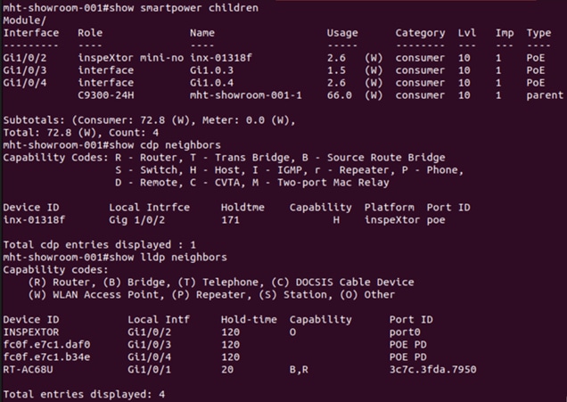
MHT Node with Cisco SmartPower Integration
Cisco SmartPower is a technology developed by Cisco for future-proofed workspaces. SmartPower provides a framework to manage and reduce energy consumption across a SmartPower domain and its connected devices. The engineering alliance between the two companies led to integrate the framework into MHT products to enable Power Monitoring and Reporting, Policy-Based Power Management leading to Energy usage Reduction with switch being the Power provider and smart Control Platform.
In the below picture, we can see how the MHT devices are joining Cisco SmartPower domain and their energy usage has been reported. This enables power policing by device type or group of devices.
Node Management Considerations
Native Functionality of PoE Solution
MHT’s PoE solutions will work natively right out of the box with their default configurations. Even without an Aida management solution, a node can still deliver DC power to supported devices. The following caveats will remain in place until a management solution such as Aida is deployed:
● Nodes by default distribute 72 watts equally across the two output channels
● Wall switches connected to the controls interface of a node will only manipulate the behavior of the output channels on the connected node only
To validate proper installation without Aida, the following features were built-in to help installers validate proper operations of the nodes:
● Connections from the output channels to downstream devices will remain solid if power is distributed correctly indicating a good connection, or will blink in the event there is a fault in the connection and power cannot be properly distributed
● If the LED indicators on the PoE interface are off but the remaining interfaces are operational, this indicates a networking issue where the node does not have an IP address assigned
● If the control interface blinks rapidly, no lldp negotiations have occurred on the node, but if blinking slowly, then lldp has successfully negotiated to configured power draw
Aida Commissioned PoE Solution
After successfully installing the cables and connecting them to the nodes, Aida provides administrators with powerful tools to manage and monitor the entire PoE solution.
Administrators can manage the PoE solution leveraging the following feature:
● Controls devices connected to any node can be used to manipulate the behavior of other nodes on the PoE network
◦ In a large space, where inevitably multiple nodes will be required to illuminate, a wall switch connected to a remote node can manipulate the behavior of output channels on other nodes by creating node clusters, whereas if Aida was not a part of the solution, a single controls device would be unable to control the behavior of remote output channels
Aida also affords administrators the following monitoring capabilities:
● Historical and real-time power draw of PoE solution
◦ Data can be provided down to the node all the way up to the entire solution
● If capable sensors are deployed:
◦ Occupancy
◦ Environmental, including but not limited to:
Temperature
Humidity
Air quality
Ambient lighting
Outcome of Validations
The following section outlines the use cases tested and the outcomes of those tests.
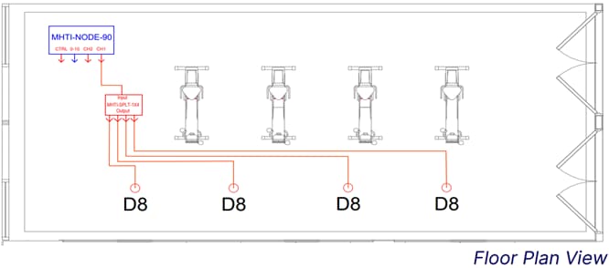
Lighting
Lighting has become a very popular use case for PoE. The tests conducted in the following section will demonstrate that MHT’s end to end lighting solution, from the PSE out to the fixtures, can provide a safe, flexible, and efficient method to illuminate a room.
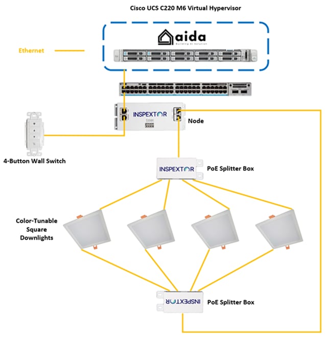
The diagram above provides a depiction of the lighting solution tested. The Catalyst C9300 ethernet switch has a single port connected to MHT node.
The node has downlinks connected to a 4-button wall switch that allows the user to adjust the brightness of the solution.
The node also has a splitter box connected to each output channel.
Each of the color-tunable square downlights have two channels, one for 2700K color temperature, and another for 5700K. The channel for 2700K on each of the four fixtures were connected to one splitter, and the 5700K channel were all connected to the other splitter. This allows for uniformity across all the fixtures to have the same color temperature.
Table 1. Bill of Materials for Lighting Use Case
| Description |
Quantity |
|
| C9300-48H-A |
Cisco Catalyst 9300 switch with 48 UPoE+ interfaces and DNAC Advantage license |
1 |
| PWR-C1-1900WAC-P |
1900-watt power supply for Catalyst 9300 series switch |
1 |
| Description |
Quantity |
|
| MHTi-NODE-90-CC |
Constant current 90-watt PoE node |
1 |
| MHTi-SPLT |
Splitter box 1 input to 4 output |
2 |
| MHTi-WS-4B |
4-button PoE wall switch |
1 |
| Aida |
MHT Aida PoE management software virtual machine |
1 |
| MHTi-DL-BARILE-SC-6-14W-AT |
MHT 6-inch, 14-watt, color-tunable square droplight |
4 |
Variables Altering Power Draw for Lighting Use Case
The variable that impacts PoE lighting solutions the most is the brightness of the fixtures. The brighter the lights are, the more power will be drawn from the PSE.
The 4-button wall switch was used to adjust the power draw up and down as necessary. For the sake of this validation, the minimum and maximum power draw were measured to gather the minimum operational power draw, as well as a worst-case scenario.
Power Draw Results for PoE Lighting
Note: Due to the fluctuations in power draw reading, the numbers displayed below are an average of readouts from “show power inline interface detail” collected every minute for five minutes.
The table below displays the results of the test cases when connecting the node to the PSE with a Cat 5e 22AWG cable of the listed length and brightness setting of the lighting fixtures.
Table 2. Power Draw Results with Cat5e 22AWG Homerun
| Homerun Length (m) |
Fixture Brightness Setting |
Average Power Draw (W) |
| 5 |
Minimum |
2 |
| 5 |
Maximum |
70 |
| 100 |
Minimum |
2 |
| 100 |
Maximum |
70 |
The table below displays the results of the test cases when connecting the node to the PSE with a Cat 6 23AWG cable of the listed length and brightness setting of the lighting fixtures.
Table 3. Power Draw Results with Cat6 23AWG Homerun
| Homerun Length (m) |
Fixture Brightness Setting |
Average Power Draw (W) |
| 5 |
Minimum |
2 |
| 5 |
Maximum |
70 |
| 100 |
Minimum |
2 |
| 100 |
Maximum |
70 |
Lighting Use Case Conclusion
The tests showed that the MHT nodes successfully delivered nearly all 71.3 watts available on the interface to the lighting fixtures. This validated that MHT’s PoE lighting solution can illuminate a space with the required lumens by using a combination of nodes to deliver the power to the connected light fixtures.
The nodes were able to receive all 70 watts across both Cat 5e and Cat 6 cables even at 100m. This shows that an optimally placed PSE can provide illumination across a large square footage of space with nodes installed using cables 100m long.
Even though the 802.3bt standard outlines the expected power at the end of a 100m, MHT will support PoE solutions that utilize cables exceeding 100m.
Furthermore, using a splitter box allows for great flexibility in how the devices are connected to the node and permits creative expressions for the occupants to utilize the 71.3 watts as they see fit.
Automated Shades
PoE as an industry continues to move forward and advancements made in both the delivery and utilization of DC power have made PoE powered automated shades a reality. The tests conducted in the following section will show that MHT nodes can effectively power and communicate with the motors to provide occupants with a comfortable environment by providing the means to alter the shade configuration to achieve desired outcomes such as daylight harvesting or supplemental cooling by blocking sunlight.
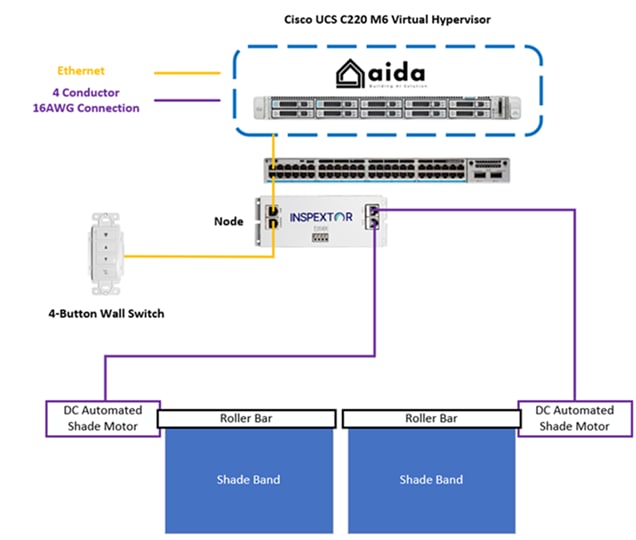
The diagram above provides a depiction of the automated shades solution tested. The Catalyst C9300 has a single home run connected to one node.
The node is connected to a 4-button wall switch that allows the user to move the shades up and down.
Each output channel is connected to a DC shade motor connected to a roller bar attached to a shade band that will roll or unroll as desired.
Table 4. Bill of Materials for Automated Shades Use Case
| Cisco Product ID |
Description |
Quantity |
| C9300-48H-A |
Cisco Catalyst 9300 switch with 48 UPoE+ interfaces and DNAC Advantage license |
1 |
| PWR-C1-1900WAC-P |
1900-watt power supply for Catalyst 9300 series switch |
1 |
| MHT Product ID |
Description |
Quantity |
| MHTi-NODE-90-CC |
Constant current 90-watt PoE node |
1 |
| MHTi-WS-4B |
4-button PoE wall switch |
1 |
| Aida |
MHT Aida PoE management software virtual machine |
1 |
The remaining components in the automated shades solution are deployed by another vendor whose components are as follows:
● DC PoE Motor Hub x 1
● DC PoE Motor x 2
● Shade Roller x 2
● Shade Bands x 5
Images of the automated shade solution in its open and closed states are below.


MHT’s technology and its product partners for third-party PoE solutions that are integrated for interoperability with Aida can be found in their partner page below.
https://mht-technologies.com/inspextor/inspextor-ecosystem/compatible-products/
Variables Altering Power Draw for Automated Shades Use Case
The variable that impacts automated shades solutions the most is the weight of the shade bands that the motors will be lifting. The shade motors will require more power to lift a larger and heavier band as opposed to smaller and lighter ones.
Due to the size and material of the bands, they were very light and did not draw considerable amount of power in their standard operating conditions. As a result, weights were attached to the bands and lifted using the 4-button wall switch until the shades would no longer move, which would be a max weight for roller, and that was found to be of an additional 40 pounds.
The show command was executed while the shades were in motion upward to measure the power draw required by the automated shades solution.
Power Draw Results for PoE Automated Shades
Note: Due to the fluctuations in power draw reading, the numbers displayed below are an average of readouts from “show power inline interface detail” collected once during each of five attempts to move the shades upward.
The table below displays the results of the test cases when connecting the node to the PSE with a Cat 5e 22AWG cable of the listed length and brightness setting of the lighting fixtures.
Table 5. Power Draw Results with Cat5e 22AWG Homerun
| Homerun Length (m) |
Weight Attached to Bands (lbs) |
Average Power Draw (W) |
| 5 |
0 |
11.9 |
| 5 |
40 |
69.1 |
| 100 |
0 |
12 |
| 100 |
40 |
70 |
The table below displays the results of the test cases when connecting the node to the PSE with a Cat 6 23AWG cable of the listed length and brightness setting of the lighting fixtures.
Table 6. Power Draw Results with Cat6 23AWG Homerun
| Homerun Length (m) |
Weight Attached to Bands (lbs) |
Average Power Draw (W) |
| 5 |
0 |
11.8 |
| 5 |
40 |
70 |
| 100 |
0 |
12 |
| 100 |
40 |
70 |
Automated Shades Use Case Conclusion
These tests prove that the node can successfully deliver the required power to operate the motors in a PoE shade solution. Advancements made by both MHT as well the shade vendors have allowed PoE shade solutions to become larger in scale by delivering power across longer distances, and in conjunction with motors becoming more efficient, more modern solutions can move larger and heavier shade bands.
The shade bands in the solution tested are comprised of five bands that are 55 inches by 60 inches. The electrical and mechanical components are capable of supporting shades significantly larger as evidenced by the solution’s capability to lift an additional 40 pounds.
The nodes are not only capable of providing the required power to the motors, but they are able to intelligently communicate with them to change their behavior as desired by the occupant. The shades can respond to a multitude of inputs such as:
● Inputs from wall switches
● Response to data collected from daylight sensors to achieve desired illumination
● Response to data collected from air quality sensors to achieve desired temperature
● Inputs from software to act on a schedule
The node proves itself capable of not only effectively providing power to the motors, but also to communicate with it to achieve desired outcomes.
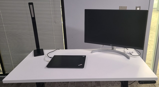
Height-Adjustable Desks
MHT offers a smart desk bundle kit that charges a battery capable of running the motors in the legs of an electronic height adjustable desk. The kit has a cradle where several of the components can be mounted. The cradle with all the components can then be mounted to the bottom of a desk for a streamlined appearance and the only external connections to it are the homeruns to the nodes under the desk.
Alternatively, if the tabletop mounted to the legs can support it, all the components can be mounted directly to the top instead of the cradle. The kit provided by MHT for this validation contained only the components required to adjust the height of the desk, to be depicted in the remainder of this section.
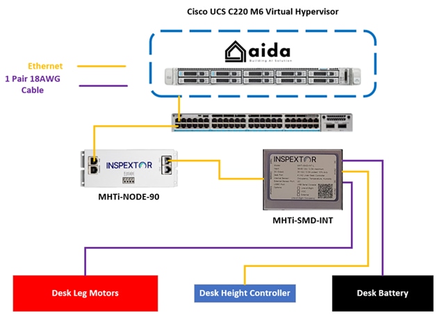
The diagram above provides a depiction of the height adjustable desk solution tested. The Catalyst C9300 switch has a single home run connected to one node.
The node is connected to a smart desk interface.
The smart desk interface is also connected to a battery which will provide the power to the motors on the legs to move the desk up and down.
The smart desk interface is also connected to a controller, which a user will use to manually adjust the height.
The smart desk interface has one last connection to the motors on the legs that will move in response to input.
Table 7. Bill of Materials for Height-Adjustable Desk Use Case
| Cisco Product ID |
Description |
Quantity |
| C9300-48H-A |
Cisco Catalyst 9300 switch with 48 UPoE+ interfaces and DNAC Advantage license |
1 |
| PWR-C1-1900WAC-P |
1900-watt power supply for Catalyst 9300 series switch |
1 |
| MHT Product ID |
Description |
Quantity |
| MHTi-NODE-90-CV |
Constant voltage 90-watt PoE node |
1 |
| MHTi-1.5ft-MRJ45-MRJ45-90 |
1.5 ft patch cord with 90-degree termination on one end |
1 |
| MHTi-RJM90-2PMF-DC |
DC cable terminated on both ends by 2-pin mini fit Jr. plug |
2 |
| MHTi-SMD-INT-L |
MHT Smart Desk Interface |
1 |
| Aida |
MHT Aida PoE management software virtual machine |
1 |
| MHTi-PoE-Cradle_TrayKit |
Mounting cradle for smart desk kit to attach under tabletop |
1 |
The remaining components of the PoE height adjustable desk solution are deployed by another vendor whose components are as follows:
● Tabletop x 1
● Height Adjustable Leg and Motor x 2
● Desk Height Controller x 1
MHT’s technology and product partners for third-party PoE solutions that can be integrated for interoperability with Aida can be found in their partner page below.
https://mht-technologies.com/inspextor/inspextor-ecosystem/compatible-products/
Variables Altering Power Draw for Height-Adjustable Desk Use Case
The variable that impacts height adjustable desk solutions the most is the charge held by the battery. The nodes themselves do not directly provide power to the motors in the legs but rather charge the battery where the motors will draw power from so as to move to the desired position.
In an effort to preserve the life of the battery, when the charge is below 50%, the smart desk interface will increase the power draw from the node to charge the battery faster. Once it reaches 50%, the interface decreases the power draw.
The battery component of the smart desk kit has an indicator light to show the charge state. Between 0% and 50% charge, the node provided more power to charge the battery quicker. When the battery was above 50%, the node reduced the provided power to charge the battery at a slower pace.
Power Draw Results for PoE Height-Adjustable Desks
Note: Due to the fluctuations in power draw reading, the numbers displayed below are an average of readouts from “show power inline interface detail” collected every five minutes across 25 minutes during the battery charge state.
The table below displays the results of the test cases when connecting the node to the PSE with a Cat 5e 22AWG cable of the listed length and brightness setting of the lighting fixtures.
Table 8. Power Draw Results with Cat5e 22AWG Homerun
| Homerun Length (m) |
Battery Charge State |
Average Power Draw (W) |
| 5 |
Below 50% |
13 |
| 5 |
Above 50% |
9 |
| 100 |
Below 50% |
13 |
| 100 |
Above 50% |
9 |
The table below displays the results of the test cases when connecting the node to the PSE with a Cat 6 23AWG cable of the listed length and brightness setting of the lighting fixtures.
Table 9. Power Draw Results with Cat6 23AWG Homerun
| Homerun Length (m) |
Battery Charge State |
Average Power Draw (W) |
| 5 |
Below 50% |
13 |
| 5 |
Above 50% |
9 |
| 100 |
Below 50% |
13 |
| 100 |
Above 50% |
9 |
Height-Adjustable Desk Use Case Conclusion
The smart desk kit works around the limitations of low voltage power by utilizing a battery to act as an energy store and the main power source to drive the motors rather than having the node directly power the motors. Given how infrequently the motors are used, the manufacturers expect the solution to be able to service the needs of the occupants and always have power available to adjust the height.
As the tests have shown, this leaves a great deal of allocated power still available to be utilized elsewhere. Especially with MHT’s variety of supported cables, other devices can be added to this solution such as a desk lamp or mobile device charger.
Furthermore, the cradle can support multiple nodes so that even more DC power can be available for use by the occupant.
The modularity of the smart desk kit lends itself very well to meet the needs of a workspace to maximize both the comfort and utility of an occupant.
External Displays
External displays can receive DC power by directly connecting to the node using a cable that is terminated with an RJ45 connector on one end, and a DC barrel plug on the other. This test will verify that the node can safely and sufficiently power the monitor across a wide variety of settings.
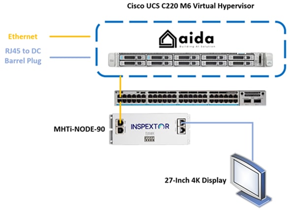
The diagram above provides a depiction of the DC powered external display. The Catalyst C9300 has a single home run connected to one node.
The node is connected to the monitor using the RJ45 to DC barrel plug cable.
Table 10. Bill of Materials for External Display Use Case
| Cisco Product ID |
Description |
Quantity |
| C9300-48H-A |
Cisco Catalyst 9300 switch with 48 UPoE+ interfaces and DNAC Advantage license |
1 |
| PWR-C1-1900WAC-P |
1900-watt power supply for Catalyst 9300 series switch |
1 |
| MHT Product ID |
Description |
Quantity |
| MHTi-NODE-90-CC |
Constant current 90-watt PoE node |
1 |
| MHTi-RJM-2Wire-2.5-2.5mm-P |
RJ45 to DC barrel plug cable |
1 |
| Aida |
MHT Aida PoE management software virtual machine |
1 |
The monitor powered by the node is a third-party display that was 27 inches with a 2180p resolution.
MHT manufacturers adapters that enables the barrel plug cable to be inserted into a variety of plug sizes and standards to provide power.
Variables Altering Power Draw for External Display Use Case
The variable that impacts DC powered external display solutions the most is the brightness of the display.
Power Draw Results for PoE External Display
Note: Due to the fluctuations in power draw reading, the numbers displayed below are an average of readouts from “show power inline interface detail” collected every minute for five minutes.
The table below displays the results of the test cases when connecting the node to the PSE with a Cat 5e 22AWG cable of the listed length and brightness setting of the lighting fixtures.
Table 11. Power Draw Results with Cat5e 22AWG Homerun
| Homerun Length (m) |
Display Brightness Setting |
Average Power Draw (W) |
| 5 |
Minimum |
14.7 |
| 5 |
Maximum |
35.7 |
| 100 |
Minimum |
14.9 |
| 100 |
Maximum |
35.4 |
The table below displays the results of the test cases when connecting the node to the PSE with a Cat 6 23AWG cable of the listed length and brightness setting of the lighting fixtures.
Table 12. Power Draw Results with Cat6 23AWG Homerun
| Homerun Length (m) |
Display Brightness Setting |
Average Power Draw (W) |
| 5 |
Minimum |
14.6 |
| 5 |
Maximum |
35.6 |
| 100 |
Minimum |
15 |
| 100 |
Maximum |
35.8 |
External Display Use Case Conclusion
The results of this test show that the node can successfully deliver DC power over the cable to the barrel plug to turn on the monitor. Even across the variables of the cable type, and length, the node displays amazing consistency in power draw from the monitor from the dimmest of settings to the brightest. This external display solution is intended to be a part of the overall Smart Desk Kit. In the test conducted in the previous section, the cradle that was mounted below the desk can support another node, which could power the monitor and add an additional PoE element to the overall desk kit.
Even if the monitor was not a part of the desk kit, the node is more than capable of powering the monitor for use by an occupant.
Conclusion
The validation tests confirm that Cisco’s Universal Power over Ethernet Plus (UPoE+) switches effectively deliver up to 90 watts of power to the MHTi-NODE-90, enabling DC power distribution to a diverse range of connected devices. This integration of MHT’s Inspextor portfolio with Cisco’s PoE infrastructure demonstrates the versatility and efficiency of PoE-based smart building solutions.
Test Results and Supported Use Cases
Comprehensive testing of the MHTi-NODE-90 showcases its ability to power multiple device types through a single node, supporting a variety of smart building applications. Devices successfully powered during the validation include:
● Light fixtures
● Height-adjustable desk batteries
● External monitors
● Control devices
● Shade motors
These results represent only a subset of the potential applications, as the MHTi-NODE-90 can deliver DC power to a broad array of devices, unlocking extensive possibilities for smart building deployments.
Cisco UPoE+ Switch Features
Cisco’s UPoE+ switches provide a robust foundation for PoE solutions, offering advanced features to enhance reliability, efficiency, and flexibility:
● Perpetual PoE
◦ Maintains power delivery to PoE devices during network maintenance, ensuring uninterrupted operation
● Fast PoE
◦ Accelerates recovery of PoE devices after power disruptions, minimizing downtime
● StackPower
◦ Enables intelligent power distribution and redundancy across stacked switches for optimized resource allocation
● Manual PoE Power Allocation
◦ Allows dynamic power distribution across multiple interfaces, overcoming limitations of static power assignments
● DHCP Support
◦ Offers extensive DHCP configuration options, providing administrators with greater control over network communication
MHT Inspextor Portfolio Capabilities
The MHT Inspextor portfolio, anchored by the MHTi-NODE-90, delivers advanced, flexible, and data-driven solutions for PoE-based smart building deployments. Designed to maximize the potential of Cisco’s UPoE+ infrastructure, the portfolio enables seamless integration, scalability, and actionable insights. Key capabilities include:
● Versatile Power Delivery and Connectivity
◦ Distributes DC power to a wide range of devices, including lighting systems, motorized shades, and ergonomic furniture, using multiple cable types such as Ethernet, coaxial, or custom connectors.
◦ Supports customizable power output configurations to match the specific voltage and wattage requirements of connected devices, ensuring compatibility and efficiency.
● Power Optimization with Splitter Box
◦ Utilizes a modular splitter box to distribute the full 90 watts of power received from Cisco UPoE+ switches across multiple devices, overcoming the physical port limitations of the MHTi-NODE-90.
◦ Enables dynamic power allocation to prioritize critical devices, enhancing system reliability and scalability.
● Advanced Data Integration and Sensor Support
◦ Collects and processes data from both MHT proprietary sensors and third-party sensors via flexible connection options, including shielded cables or RS485 spring cage connectors.
◦ Supports a variety of sensor types, such as temperature, humidity, motion, and CO2 sensors, for comprehensive environmental monitoring and control.
● Occupancy Sensors
◦ Enable real-time utility optimization by adjusting lighting, HVAC, and other systems based on occupancy detection.
◦ Generate detailed utilization reports to identify trends, optimize space planning, and reduce energy waste in underutilized areas.
● Air Quality Sensors
◦ Monitor environmental parameters, including volatile organic compounds (VOCs) and particulate matter, to maintain safe and comfortable indoor conditions.
◦ Integrate with building management systems to trigger ventilation or filtration adjustments, enhancing occupant health and safety.
● Daylight Harvesting
◦ Combines data from daylight and air quality sensors to dynamically adjust automated shades, balancing natural light intake with thermal comfort.
◦ Reduces reliance on artificial lighting by optimizing window shading, contributing to energy savings and occupant well-being.
● Real-Time and Historical Monitoring
◦ Provides a centralized dashboard for real-time monitoring of PoE solution performance, including power consumption, device status, and environmental conditions.
◦ Stores historical data for trend analysis, enabling predictive maintenance and resource optimization based on usage patterns.
● Interoperability and Scalability
◦ Integrates seamlessly with third-party building management systems (BMS) and IoT platforms via standard protocols such as MQTT, BACnet, or REST APIs.
◦ Supports modular expansion, allowing additional MHTi-NODE-90 units or sensors to be added as building requirements evolve.
These capabilities empower system integrators, facility managers, and engineers to design tailored PoE solutions that enhance operational efficiency, occupant comfort, and sustainability.
Strategic Impact
The strategic alliance between MHT and Cisco, enabled by the Cisco Engineering Alliance, creates a pathway towards more sustainable and productive environments. By integrating MHT's innovative PoE hardware with Cisco's advanced UPoE+ switches and third-party integrations, the partnership delivers scalable, energy-efficient PoE solutions. These solutions not only improve user productivity and efficiency but also drive progress towards net-zero energy goals through greater automation and enhanced user experiences.