Non-Disruptive SAN Migration from Brocade to Cisco
Available Languages
Bias-Free Language
The documentation set for this product strives to use bias-free language. For the purposes of this documentation set, bias-free is defined as language that does not imply discrimination based on age, disability, gender, racial identity, ethnic identity, sexual orientation, socioeconomic status, and intersectionality. Exceptions may be present in the documentation due to language that is hardcoded in the user interfaces of the product software, language used based on RFP documentation, or language that is used by a referenced third-party product. Learn more about how Cisco is using Inclusive Language.
- US/Canada 800-553-2447
- Worldwide Support Phone Numbers
- All Tools
 Feedback
 Feedback
Introduction
Today’s SAN administrators are faced with an increasing need for storage as time progresses. Per a survey done by ESG in March 2020, more than 71% organizations are looking at deploying or have already deployed NVMe-based solid-state or flash storage technology. To support the burst of this technology, they require high performance and redundant SAN networks that can both meet their current demands and scale for growth in the future. To accommodate these new requirements, SAN administrators often migrate or upgrade from their existing storage networks.
Included below is information on similar topics like why, what, and how to choose new MDS 9000 series fabric switches, their features, competitive advantages and finally the migration plan from Brocade to Cisco SAN switches.
What you will learn?
This document provides an overview of,
● Cisco MDS 9000 series switches and Cisco NX-OS software features
● Competitive features of Cisco MDS 9000 series switches
● SAN Migration planning, process, strategies, and execution
● Limitations, precautions, and verifications
● SAN technology concepts and terms
Why migrate to Cisco SAN Switches? (Top-of-mind questions)
What comes to your mind when you think about switching our SAN vendor? Some of those criteria are:
1. Total cost of ownership and Investment protection
2. Future software and hardware upgrade support
3. Interoperability, redundancy and high availability (the famous 5x 9s of Data Centre)
4. Flexibility (Multi-protocol support, link aggregation, etc.)
5. Security (How secure our data is in the new environment)
6. Management (New management platform, new licenses, learning curve, etc.)
7. Operations and administration (ease of troubleshooting, Technical support, etc.)
8. Feature support (trunking, security, FICON, Port license, etc.)
Cisco® MDS 9000 Family SAN switches are recognized across the data center industry for their reliability, flexibility, performance, and investment protection since 2002. The Cisco MDS 9000 Family portfolio includes the Cisco MDS 9700 Series Multilayer Directors, the multiprotocol Cisco MDS 9200 Series Multiservice Switches, and the fixed form-factor Cisco MDS 9300 and 9100 Multilayer Fabric Switches. These switches provide industry unique features in security, flexibility, visibility, redundancy, high availability, and high performance at the core and edge levels, with room for future growth.
The 64G Fibre channel MDS 9700 directors, along with 32G Fibre Channel fabric switches include some of the hardware-based features, integrated with software to enhance security, deep frame level visibility and built-in redundancy. We will take a deep dive to discuss some of these features in detail. And to take advantage of some of these unique technology features, Brocade customers have to go through cycles of migrating storage network switching from Brocade to Cisco MDS 9000 series switches. When we talk about SAN migration, customers are concerned about disruption to their existing (Brocade) SAN environment, adopting new technology, and daily operations. They may have questions like:
1. Is this (SAN migration) a disruptive process?
2. How much time and how many maintenance windows we will need to schedule?
3. What sort of migration strategy I can apply and how to migrate?
4. Are there any Cisco verified resources to help us with migration from Brocade to Cisco SAN switches?
5. Do we have any labs / demos to have hands-on practice with Cisco SAN switches, along with GUI management?
The SAN migration can be relatively easy and painless process if performed with appropriate planning, design, and execution.
This document helps you evaluate options for SAN migration including third-party solutions as well as the Cisco MDS 9000 series-based SAN switching family. At the same time, we will also briefly talk about some of tools to help with daily administration of Cisco MDS switches-based SAN.
But before we dive into those specific migration details, let’s take a look at the Cisco MDS 9000 series SAN switching portfolio and what it has to offer.
Brief overview of Cisco MDS SAN Switches
This section contains the following topics:
● MDS 9000 Series FC Fabric Switches
● MDS 9000 Series Multilayer Fabric Switches
● Cisco NX-OS Software Features
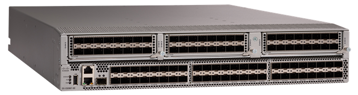
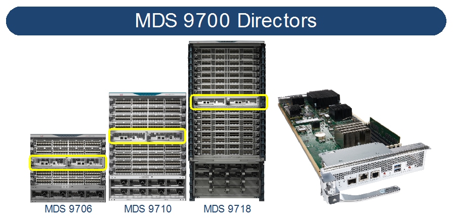
Cisco MDS 9700 Series Multilayer Directors deliver superior performance, a fault-tolerant design, and multiprotocol flexibility support with nonstop operations. The Cisco MDS director switches are qualified for NVMe-ready today. This platform has three different models: MDS 9706, MDS 9710, and MDS 9718.
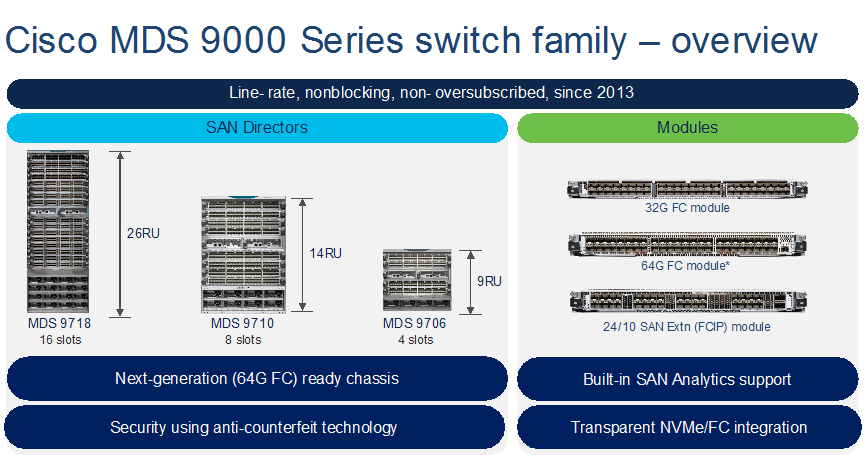
MDS 9706
Launched in 2015, MDS 9706 can support up to 24Tbps of chassis bandwidth using 192 ports @2/4/8/10/16/32/64G FC line-rate speeds. This is the ideal chassis for those looking at fabric switch consolidations in a small director chassis. It comes with 4-linecard slots, 4-power supply slots and up to 6-fabric module slots. A single 42RU rack can accommodate up to 4x MDS 9706, ideal for smaller footprint, smaller storage networks and for pod-based data center infrastructure. MDS 9706 can provide flexible port-density with a lower rack space (9RU), along with higher scalability, N:N GRID level power supply redundancy and non-disruptive software and hardware upgrades.
MDS 9710
Launched in 2013, the first chassis in 9700 series directors is MDS 9710. It can support up to 48Tbps of chassis bandwidth using 384 ports @2/4/8/10/16/32/64G FC line-rate speeds. One of the best-selling directors in the industry, this is the chassis for those looking for redundancy, flexibility, future growth and increased scalability. This chassis has 8-linecard slots, 8-PSU slots and up to 6-fabric module capacity. MDS 9710 can provide all the benefits of MDS 9706, along with higher port density and N+2:N+2 GRID level power supply redundancy.
MDS 9718
In 2016, MDS 9718, industry’s highest port-density director was launched. This is the only director in its class across the industry that can support up to 768 port linerate ports 2/4/8/10/16/32/64G FC speeds. With up to 96Tbps of chassis bandwidth, it is the ideal candidate for consolidating multiple smaller directors or fabric switches. Two 8-slot chassis or Four 4-slot chassis can be consolidated into single MDS 9718. . This is the ideal chassis for customers looking at multiple directors and fabric switch consolidations in a single director class chassis. It simplifies the cost, management, and reduces cabling by large extent. MDS 9718 has 16-linecard modules, 6x fabric modules and 16-power supply slots to provide industry’s higher port-density in a single chassis with N+4:N+4 PSU redundancy.
To support MDS 9700 directors, there are multiple modules. 48-port 16G-linecard module, 48-port 32G-linecard module, 48-port 10GE FCOE module, 24-port 40GE FCoE modules, and 24/10 SAN Extension module that supports 24x 16G FC ports and up to 40GE FCIP connectivity. 16G-linecard, 10GE FCoE linecard and 40GE FCoE linecards are end-of-sale as of today. Customers looking at FCoE connectivity options should look at Nexus 9000 series switches which has built-in FCoE support. Now, let’s look at the currently available linecards for MDS 9700 directors briefly.
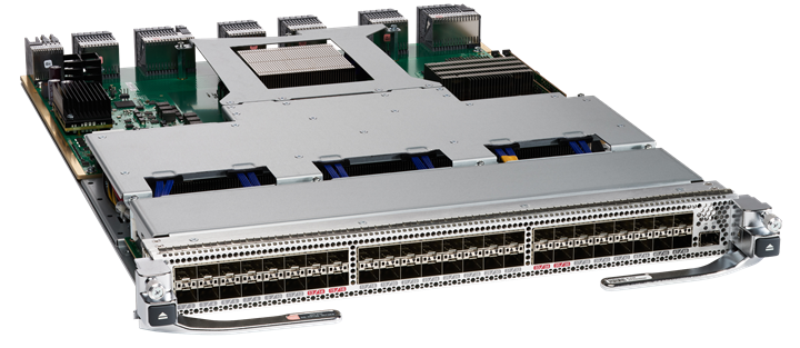
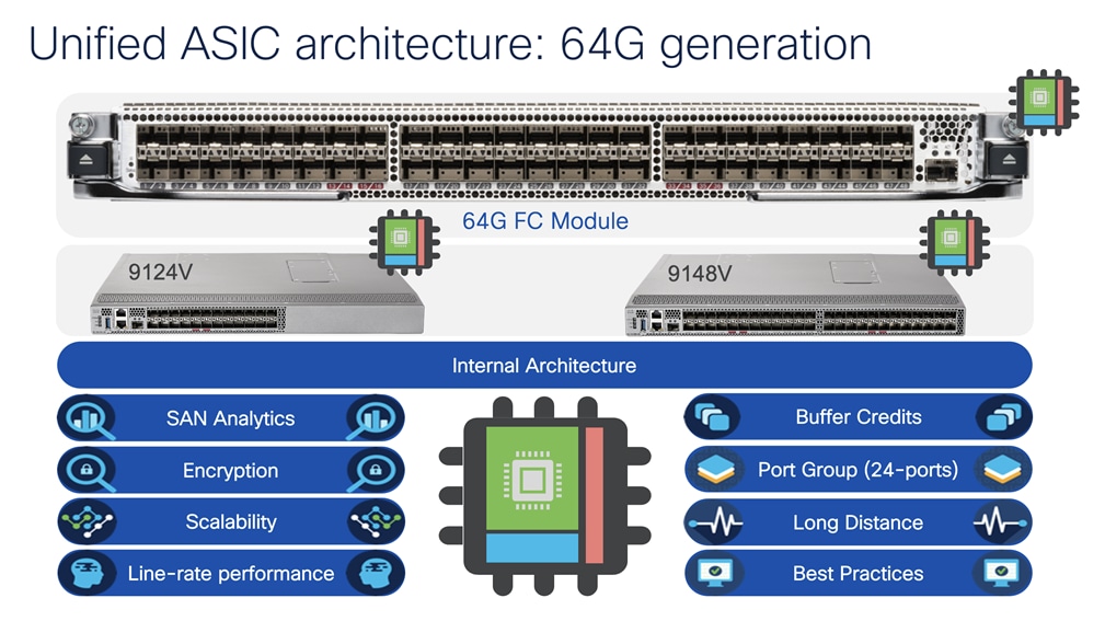
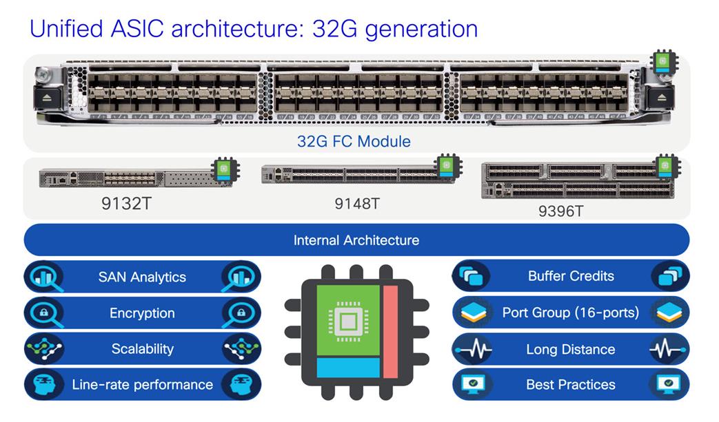
48-port 64G FC module
With 48-port density, this module supports linerate 8/16/32/64G FC speeds. Using 32G optics, you can achieve 8/16/32G FC speed & using 64G optics, customers can achieve 16/32/64G FC speeds at line rate performance. This module has enhanced SAN Analytics feature to provide the packet visibility in high density SCSI / NVMe environment. This module can provide multiple interfaces that can send any FC packet @ 64G speed to more than 500KMs. This module also supports new innovative features like Dynamic congestion control using DIRL, Anticounterfeit security with secure boot technology, and few more.
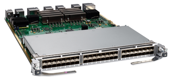
48-port 32G FC module
With 48-port density, this module supports linerate 4/8/16/32G FC speeds. Using 16G optics, customers can achieve 4/8/16G FC speed & using 32G optics, customers can achieve 8/16/32G FC speeds at line rate performance. This module has built-in Network Processing Unit to support hardware-based SAN Analytics. With up to 24,900 buffer credit support, this module can provide multiple interfaces that can send any FC packet @ 32G speed to more than 500KMs. This module also supports new, innovative features like Dynamic Congestion Control using DIRL, Anticounterfeit Security with secure boot technology, and few more.
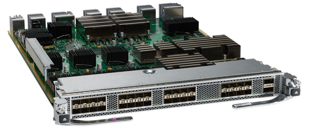
24/10-SAN extension module
This module has multiple unique use cases of extending fibre channel connectivity across multiple DCs, located at very large distances. Because we are sending FC packet over IP, we are no more limited by buffer credits or DWDM circuits. We can say goodbye to high cost, high maintenance DWDM circuits and start consolidating our FC network across DCs over IP WAN. This module can provide up to 80Gbps un-compressed throughout using its 8x10GE / 2x40GE interfaces. It can also support FC speed of 2G an 10G for legacy device connectivity.
MDS 9000 Series FC Fabric Switches
Similar to MDS 9700 directors, we have different flavors of 64G & 32G FC fabric switches. Let’s look at them one-by-one.
MDS 9124V
With up to 24-port density, this 1RU switch comes with the base license of 8-port activation, with incremental 8-port upgrade license. You can upgrade this switch from 8-port to 16- & 24-port, as and when needed. This helps to plan out budget and spread cost over the time. This switch includes the enhanced F64 ASIC to support low power, high performance, along with enhanced Analytics capability. This switch comes with bidirectional airflow support as well, with hot-swappable power supplies and fan trays.
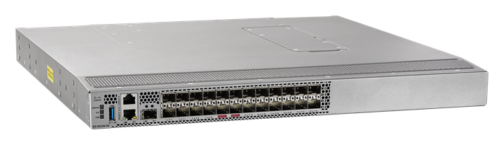
The Cisco MDS 9124V Fibre Channel switch provides state-of-art SAN Analytics and telemetry capability built into its next-generation Application-Specific Integrated Circuit (ASIC) platform. The Non-Volatile Memory express (NVMe)-ready switch allows seamless transition to Fibre Channel Non-Volatile Memory Express (NVMe/FC) workloads whenever available without any hardware upgrade in the SAN. This switch empowers small, and midsize enterprises that are rapidly deploying cloud-scale applications using extremely dense virtualized servers, providing the benefits of greater bandwidth, scale, and consolidation.
MDS 9148V
The Cisco MDS 9148V supports up to 48-port density. This 1RU switch comes with the base license of 24-port activation and incremental 8-port upgrade license. We can upgrade this switch from 24-port to 32- , 40- & 48-port, as and when needed. This helps to plan out budget and spread cost over the time. This switch includes the enhanced F64 ASIC to support low power, high performance, along with enhanced Analytics capability. This switch comes with bidirectional airflow support as well, with hot-swappable power supplies and fan trays.
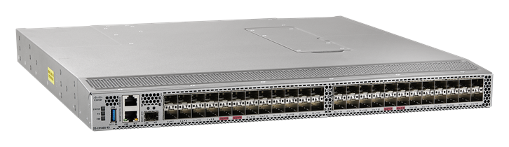
The Cisco MDS 9148V Fibre Channel switch provides state-of-art SAN Analytics and telemetry capability built into its next-generation Application-Specific Integrated Circuit (ASIC) platform. The Non-Volatile Memory express (NVMe)-ready switch allows seamless transition to Fibre Channel Non-Volatile Memory Express (NVMe/FC) workloads whenever available without any hardware upgrade in the SAN. This switch empowers small, and midsize enterprises that are rapidly deploying cloud-scale applications using extremely dense virtualized servers, providing the benefits of greater bandwidth, scale, and consolidation.
MDS 9132T
The Cisco MDS 9132T 32-Gbps 32-Port Fibre Channel switch provides high-speed Fibre Channel connectivity from the server rack to the SAN core. It empowers small, midsize, and large enterprises that are rapidly deploying cloud-scale applications using extremely dense virtualized servers, providing the dual benefits of greater bandwidth and consolidation. Small-scale SAN architectures can be built from the foundation using this low-cost, low-power, nonblocking, line-rate, and low-latency, bidirectional-airflow-capable, fixed standalone SAN switch connecting both storage and host ports. Medium-size to large-scale SAN architectures built with SAN core directors can expand 32-Gbps connectivity to the server rack using these switches either in switch mode or Network Port Virtualization (NPV) mode.
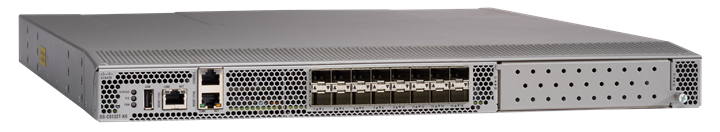
This 1RU switch can start with 8-port base license, can scale up to 32-port density. This switch has 8-port port expansion license and an additional 16-port Logical Expansion (LEM) module that adds 16 physical ports to the switch. With built-in SAN Analytics, this is an ideal candidate for a very small SAN, with the lowest price point. This switch supports bi-directional airflow support with hot swappable and redundant components like power supplies and fan trays.
MDS 9148T
With up to 48-port density, this 1RU switch starts with 24-port base license with incremental 8-port license. You can upgrade this switch from 24-port to 32-, 40-, 48port, as and when needed. This helps to plan out budget and spread cost over the time. This switch comes with bidirectional airflow support as well, with hot-swappable power supplies and fan trays. The Cisco MDS 9148T Fibre Channel switch provides state-of-art SAN Analytics and telemetry capability built into its next-generation Application-Specific Integrated Circuit (ASIC) platform.
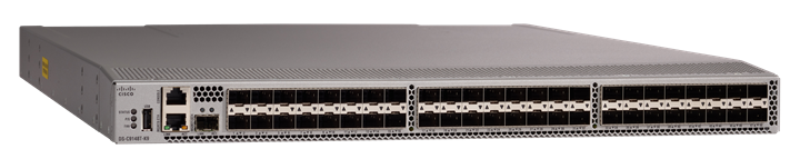
The Non-Volatile Memory express (NVMe)-ready switch allows seamless transition to Fibre Channel Non-Volatile Memory Express (NVMe/FC) workloads whenever available without any hardware upgrade in the SAN. This switch empowers small, midsize, and large enterprises that are rapidly deploying cloud-scale applications using extremely dense virtualized servers, providing the benefits of greater bandwidth, scale, and consolidation.
MDS 9396T
This 2RU switch as 96-port density and start with 48-port base license with 16-port addon licenses to move the port density from 48-port 64-port 80-port 96-port density. Again, with bidirectional airflow support and hot swappable and redundant components like power supplies and fan trays, it has built-in redundancy and flexibility to address higher port density in just 2RU space requirement. This switch is an ideal candidate where customers have limited rack space and can’t fit in the director chassis. The Cisco MDS 9396T Fibre Channel switch provides state-of-art SAN Analytics and telemetry capability built into its next-generation Application-Specific Integrated Circuit (ASIC) platform.
The Non-Volatile Memory express (NVMe)-ready switch allows seamless transition to Fibre Channel Nonvolatile Memory Express (NVMe/FC) workloads whenever available without any hardware upgrade in the SAN. This 96-port high-density, highly reliable and scalable, enterprise-class switch is ideal for medium to large departmental SANs.
MDS 9000 Series Multilayer Fabric Switches
MDS 9250i
The only 16G fabric switch which supports FC, FCIP and FCoE in a small 2RU space. This switch has 40x 16G FC ports, 8x 10GE FCoE ports and 2x 10GE FCIP ports. This switch is an ideal candidate for creating business continuity or disaster recovery solution with multiple data centers. It can send the FC packet over IP and can do active-passive failover for building redundancy. The FCoE ports can connect to ethernet switches/FCoE targets or hosts for convergence, FC ports can connect to FC hosts / storage devices and FCIP can send the packet to remote data center for data replication. The switch comes with 20x 16G FC ports, 8x10GE FCoE ports and 2x 1/10GE FCIP ports enabled with base license. There is additional 20x16G FC port license. The FCIP ports are enabled by default with 1/10GE speed support.
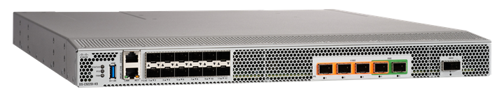
MDS 9220i
The latest generation FCIP switch comes in 1RU format with 12x 32G FC ports and 4x1/10GE or 2/25GE or 1x40GE FCIP ports. The switch comes with redundant hot swappable components and support bidirectional airflow support. The 32G FC ports can connect to any FC hosts / storage ports while FCIP ports can provide IP connectivity to remote data centers for FC traffic at 1/10/40GE speeds. The switch comes with 2x 1GE FCIP ports, 4x32G FC ports enabled with base license. Additional port upgrade license can be applied to enabled rest of the FCIP ports and FC ports.
Customers buying Cisco MDS SAN switches have some of the unique software features as well. There are lot of common features but for now, let’s briefly look at some the key features.
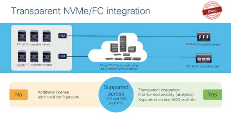
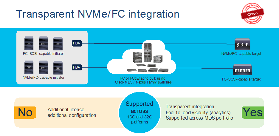
NVMe/FC support
NVMe/FC is supported across the current Cisco MDS 9000 series switches. Without adding any license or enabling any feature, MDS 9000 series switches are ready to support NVMe based devices (servers or storage arrays) using any NX-OS 8.x release.
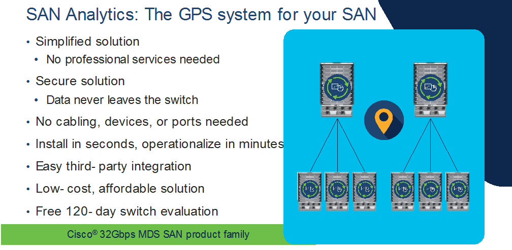
SAN Analytics
Cisco MDS 32G platform (including fabric switches and directors) switches are capable of providing deep packet visibility for SCSI and NVMe workloads simultaneously. SAN Analytics can provide fabric level visibility from three different perspectives – server / storage / ISLs (Bird’s eye view). It can present deep level visibility across initiator to target to LUN. The ports can operate at any speed – 4/8/16/32G and can use either 16G or 32G optics. SAN Analytics can provide more than 70+ different metrics across the fabric and can be a useful tool to troubleshoot any physical level to application-level issue. Each 32G hardware has built-in Network Processing Unit (NPU) which looks at headers of any/all packets traversing through switches. SAN Analytics is a hardware-based solution. Means it does not consume memory or switching CPU cycles to perform functions / calculations. Plus, there is a dedicated processor to perform analytics functionality. This will free up the resources for regular switching tasks. This is a secured tool as it doesn’t look at the data payload of the packet. The NPU analyzes everything using FC header information and will present information such as latency / bandwidth consumption and several other parameters at any time across the fabric. From the header information, it can identify the source, destination, bandwidth, Data-access latency, fabric latency, etc. at a click of a button. The metrics information is streamed from management port of switch in gRPC format and can be presented using DCNM or any 3rd party tool like Virtana’s Virtual Wisdom, etc.
For more details about SAN Analytics, click here.
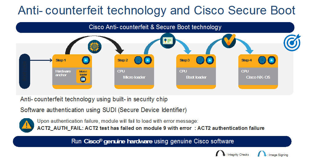
Security
Cisco MDS 9700 directors have a unique security feature called Anticounterfeit Security with secure boot. This feature helps validate genuine Cisco hardware running genuine Cisco software at bootup. This is a non-intrusive feature for customer, no configs or any additional license needed. It verifies the hardware and software at the bootup and makes sure the digital fingerprint matches internally before getting into operational mode.
AutoZone
The AutoZone feature takes care of the most tedious task of Fibre channel – creating zones automatically. It is a mechanism to automate zoning of devices (initiators to targets only). This feature is very useful in smaller single switch fabric, with less than 250 devices. This can be a day-zero or day-one tool to help with fresh install. The zones created by AutoZone are also resource efficient as they save TCAM memory and other resources by not creating zone entries for initiator-to-initiator or target-to- target. This feature is available only in single switch fabric. If the switch detects any ISLs / E-ports, it will disable this feature automatically. For more details, click here.
Unified feature capabilities across Cisco MDS 9000 series fabric switches and modules
MDS 64G & 32G FC fabric switches have some of the unique but common feature set among themselves. These switches use the same port ASIC from 64G / 32G FC linecard from MDS 9700 directors. Which means, these switches are small but provides similar capacity as of a 64G / 32G FC linecard in a director switch per port group. Each 64G fabric switch has 24-port port group with the capacity of up to 24576 buffer credits for each port group, Can assign up top 16000 buffer credits to a single port out of any port group. Each 32G fabric switch has 16-port port group, with the capacity of up to 8300 buffer credits per port group or assigning up to 8270 buffer credits to a single port out of any port group. These switches also come with built-in hardware to support SAN Analytics. The Anticounterfeit security helps to make sure our customers are running Cisco genuine hardware with Cisco genuine software in their data centers. Using the same port ASIC, these switches can provide similar number of encryption strength per port group.
Cisco NX-OS: Cisco NX-OS pioneered new operating system for the Cisco data center switches. NX-OS was known as SAN-OS in the earlier days (prior to 3.x release). It is built with much more resiliency, ease to operate, troubleshoot and secure. It is less vulnerable to security issues due to separation of Linux OS kernel and NX-OS. Cisco NX-OS also provides single and flat command line structure set for multiple VSANs compared to multiple different partitions and sets for each Fabric-ID in Brocade FOS.
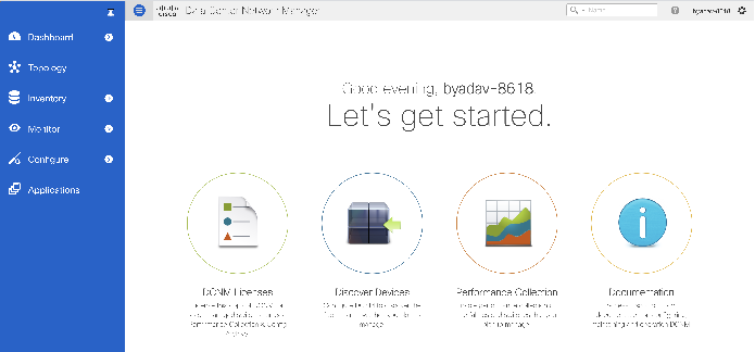
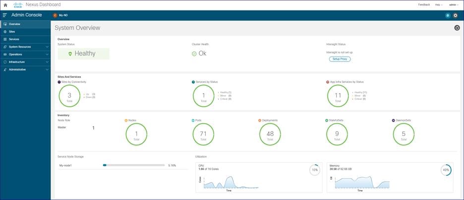
Cisco SAN Management – Nexus Dashboard Fabric Controller (NDFC)
Cisco Nexus Dashboard Fabric Controller aka NDFC (formerly known as Data Center Network Manager aka DCNM) runs exclusively as an application service on top of the Cisco Nexus Dashboard Cluster. Nexus Dashboard cluster uses Kubernetes at its core with customized extensions, thereby realizing secure and scaled-out platform for deployment of microservices-based applications. Nexus Dashboard Cluster provides Active/Active HA (High Availability) for all applications running on top of that cluster. Cisco Nexus dashboard fabric controller is the new management platform for Cisco SAN switches. We can manage Cisco MDS 9000 Series Switches using NDFC. Cisco NDFC enables you to manage multiple devices, multiple fabrics across multiple locations while providing ready-to-use capabilities, such as, control, automation, monitoring, visualization, and troubleshooting.
Competitive Advantages of Cisco MDS 9000 Series Switches
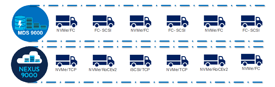
NVMe Anywhere
Cisco’s Nexus data center product switching family which supports Ethernet, FC and FCoE. Cisco MDS 9000 series switches support FC and FCoE. Nexus and MDS both support NVMe. Nexus switching family can support NVMe/RoCEv2, NVMe/TCP, NVMe/FC or NVMeoF and MDS can support NVMe/FC. In other words, the new rise of NVMe storage protocol is compatible with Cisco’s data center switches, irrespective of the transport protocol. Such a transport agnostic solution from Cisco Data center switches is unique because:
Same NX-OS is used in both switching families and same management software – DCNM can be used to manage individual fabrics, comprising of Nexus / MDS SAN switches.
As a result, this reduces complexity in deployment, operational and administration cycle, providing single pane of glass and full visibility across the data center.
Another advantage is, Nexus can be integrated in ACI / NX-OS based fabric thus enables the converged solution for customers, helping them streamline their operations across data center.
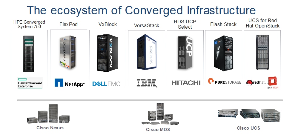
Wider Ecosystem Integration
Cisco MDS 9000 series switches are part of converged infrastructure solutions from different vendors. This helps streamline deployment and operations across multiple vendors and provides flexibility to customer, to provide transparent Cisco MDS SAN switch integration in any selected converged system. Converged infrastructure solutions are designed for various workloads using Cisco MDS 9000 SAN switches, Cisco Nexus data center switches and Cisco Unified compute system. More Cisco validated Designs (CVDs) can be found here for some of the converged infrastructure vendors.
Investment Protection
Investment for Chassis: This is one of the key benefits for Cisco MDS 9000 series directors and switches. Initially, when announced in 2013, the Cisco MDS 9700 directors supported 16G FC speed at linerate (during 2013 timeframe). In 2017, same directors were able to support 32G linerate performance. And since September 2019, these directors are now capable of supporting 64G module at linerate performance in the same chassis.
Table 1. Estimated investment for each generation upgrade in MDS 9700 chassis
| Chassis Component |
Speed upgrade: 16G to 32G FC |
Speed upgrade: 32G to 64G FC |
| Chassis |
None |
None |
| 16G Modules |
None |
None |
| 16G Optics |
None |
None |
| 32G Modules |
As needed, when needed |
None |
| 32G FC optics |
As needed, when needed |
None |
| 64G Modules |
None |
As needed, when needed |
| 64G FC optics |
None |
As needed, when needed |
| Fabric Module |
None |
May be |
| Supervisor Module |
None |
May be |
| FAN trays |
None |
None |
| Power supplies |
None |
None |
| Optical Fiber cables |
None |
None |
| NDFC licensing |
None |
None |
| Chassis Licensing |
None |
None |
The fabric switches also provide investment protection as they use the same port ASIC that is used in 32G director module. In other words, the long-distance connectivity, encryption capacity, amount of buffer credits supported across the port-group remains same. This helps SAN architecture and other administrators to buy something they need from actual usage perspective, irrespective of the features they need.
Investment protection for Optics:
Cisco MDS 9000 series switches also support existing optics support. For example, customer can continue using 16G and 32G optics in the same chassis, in the same or newer modules. Off course, the speed will be determined by SFP supported but there is no need to buy new optics, if you don’t need them. The existing optics will be supported on the newer platform as well. More details on transceiver compatibility can be found here: https://www.cisco.com/c/en/us/products/collateral/storage-networking/mds-9000-series-multilayer-switches/product_data_sheet09186a00801bc698.html
And the investment protection continues with management platform as well.
SAN Analytics
One of the unique features of Cisco MDS 9000 series switches is its deep packet visibility. SAN Analytics provides deep packet visibility which helps to find the data access latency, throughput, number of IOPS, frame size, etc. across the fabric. This is a hardware-based feature, supported across 32G and future hardware. We can turn ON / Off Analytics on any port, across any module at any time without interrupting the regular switching traffic. SAN Analytics provides information for SCSI as well as NVMe flows. Further, this is a very secured feature as the analytics engine will only look inside the header of every frame, not inside the data portion of the frame. So, the data remains intact, without anyone touching it.
Security
Anticounterfeit Technology using Secure Boot: Cisco MDS 9000 series switches provide enhanced Anticounterfeit technology based secure boot process. This feature makes sure that the hardware and software mounted on top of hardware are Cisco genuine and authenticated. If any one of the components is corrupt or tampered with or malware impacted, it will throw ACT authentication failure during bootup sequence for the bad component. for more details, see https://blogs.cisco.com/datacenter/cisco-mds-9000-series-switches-security-is-better-when-it-is-built-in-not-bolted-on.
VSAN and Smart Zoning
VSAN are Virtual SAN fabrics that can span, across a single fabric. This will cater to isolate traffic between each VSAN, while leveraging the same hardware resources. Inter VSAN Routing (IVR) allow to share valuable resource (i.e.) tapes across multiple logical fabrics by protecting their integrity. To optimize hardware resources and to facilitate zoning operations, Cisco has developed a unique zoning feature called Smart Zoning. Each WWN will be identified as either initiator or target, automatically by switch. And will create zoning configuration based on this database. Now, even having multiple targets and initiators in a single zone, single initiator/target zoning will be applied. This helps us optimize the TCAM memory and other resources across multiple switches and fabric.
Dynamic Ingress Rate Limiting (DIRL)
Dynamic Ingress Rate Limiting (DIRL) is used to automatically limit the rate of ingress commands to reduce the egress traffic that can cause congestion due to high link utilization of buffer credit starvation leading into slow drain. DIRL eliminates the congestion that can occur in the egress direction. DIRL does this by reducing the rate of IO solicitations such that the data generated by these IO solicitations matches the ability of the end device to actually process the data generated by these IO solicitations matches the ability of the end device to actually process the data without causing any congestion. As the device's ability to handle the amount of solicited data changes, DIRL, will dynamically adjust seeking to supply it the maximum amount of data possible without the end device causing congestion. After the end device recovers from congestion, DIRL will automatically stop limiting the traffic that is sent to the switch port. DIRL is comprised of two functions and can perform equally well on congestion caused both slow drain and over utilization:
Fabric Performance Monitor (FPM)
DIRL actions are taken by FPM as notified by port monitor. On detecting a rising threshold from port monitor, FPM does rate reduction causing the rate of ingress traffic to be reduced. On detecting the value of a counter being below the falling threshold continuously for the DIRL recovery interval, FPM does rate recovery.
Redundancy
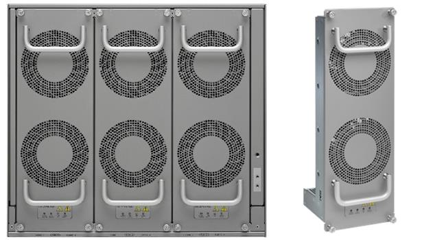
Cisco MDS 9000 series switches have redundant components like power supply, fabric modules, and supervisor modules. These components help us provide non-stop operations for the switches. All of the power supplies used in Cisco MDS series switches are 80Plus Platinum certified.
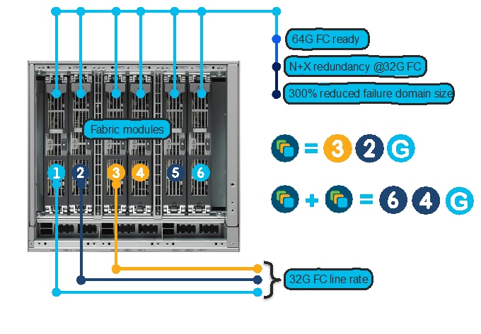
Fabric Modules
Fabric modules provide backplane connectivity for all modules through the backplane. Fabric modules are fitted vertically inside the chassis (in the back side, behind fan trays) while line cards are fitted horizontally inside the chassis, from the front side. This way, every fabric module has connection to every linecard in the chassis. This provides the redundancy in case of any linecard or fabric module failure. There are six fabric modules in the back on the chassis. In case of lost fabric module, it will only impact about 17% bandwidth performance of the chassis. Having at least 3x Fabric-3 modules in any MDS 9700 chassis will provide linerate 32G performance. But having 6x fabric-3 modules in a chassis provides N:N redundancy. For 48-port 64G FC module to operate at linerate, all 6x Fabric-3 modules are needed.
Port Channels
The architecture used in Cisco MDS 9000 series switches provide more redundancy between multiple ASICs, modules, and chassis. Port-channel feature allows aggregation of up to 16 ISLs between any MDS switches. use Any port from any fabric switch and any port on module in a director switch can be used to create a port channel between chassis. Using 16x 32G ISL members, it can provide up to 512G of aggregated bandwidth, or up to 1TB of aggregated bandwidth using 16x 64G ports.
Power Supply
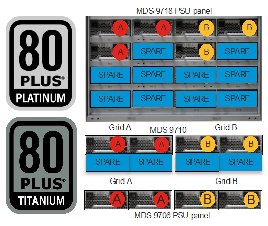
MDS 9000 series fabric switches have redundant power supplies, redundant fan-trays, and bi-directional airflow support. MDS 9700 series director switches have GRID level power supply redundancy. MDS 9706 has N:N, MDS 9706 has N+2:N+2 and MDS 9718 has N+4:N+4. With fully populated power supply bays, MDS 9710 and MDS 9718s can afford to lose up to 2 / 4 PSUs from any GRID and continue to provide GRID level redundancy. Further, MDS 9700s can support HVDC circuits and also AC/DC PSUs in same chassis. Having GIRD level power redundancy helps provide non-stop operations to SAN fabric. This is a huge benefit as without GRID redundancy, single power spike can result in reboot of director class chassis which tan take 20-45 minutes to come back online. These director chassis use only needed power and rest is maintained in reserve. The AC power supplies are 80Plus platinum certified and DC power supplies are 80Plus Titanium certified.
Dual Supervisor Modules
Every director comes with dual supervisor module. Means any single supervisor module failure, will keep chassis running its control plane functionality (zoning, configuration, etc.). The supervisor module is only managing the switches and doesn’t sit in the data path.
Hot Swappable Fan Trays
MDS 9700s have multiple fan trays, and each fan-tray has multiple fans, with each FAN having redundant power and control plane connectivity. This helps to maintain the temperature within MDS 9700 directors.
Cisco MDS 9000 series switches are designed to meet 99.9999% uptime SLA to meet critical data center demands. Due to built-in redundancy in its legacy platform which continues in new 16G/32G/64G MDS SAN switches as well, these switches are capable of providing non-stop operations.
Non-disruptive Software Upgrades/Downgrades
In-service software upgrade (ISSU) or In-service software downgrade (ISSD) is one of the features that’s been around for long time. This feature helps with non-disruptive software upgrade or downgrade on any MDS fabric switch – director switch. Customers can major release software upgrades or minor release software upgrades / downgrades using this feature. This is supported across MDS fabric switches and director switches.
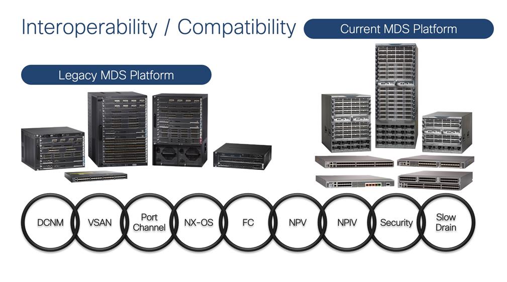
Interoperability (within MDS)
MDS legacy platforms: Because Cisco MDS switches are using same architecture since this platform was launched in 2002, they are easy to interoperate between multiple generations. Now end-of-sale 48-port 16G FC module, 48-port 10GE FCoE module and 24-port 40GE FCoE modules are also supported on any of the MDS 9700 chassis. The same chassis supports 48-port 32G FC module, and 64G FC module at linerate speed. In other words, any MDS 9700 chassis can support six different modules, mix and match as per the requirement. This is a great flexibility for customers as MDS 9700 can support any legacy devices running at 2G speed and newer NVMe arrays @ 64G speeds, all at the same time, in same chassis. From FCIP connectivity perspective, Cisco can also offer a 40GE FCIP link between 24/10 SAN Extension module on MDS 9700 chassis and MDS 9220i or a 10G FCIP link to MDS 9250i.
Optics/Transceivers
Cisco MDS 9000 series switches support multiple generations of optics / transceivers. Each generation of transceiver supports three different speeds. Like 16G FC optics can support 4/8/16G FC speed, 32G FC optics can support 8/16/32G speed and 64G FC optics can support 16/32/64G FC speeds. These are common optics across multiple generations of linecards / modules. More details about the transceiver compatibility with different linecards can be found here: https://www.cisco.com/c/en/us/products/collateral/storage-networking/mds-9000-series-multilayer-switches/product_data_sheet09186a00801bc698.html
Cisco MDS 9000 Switch Selection
When we have such a broader SAN switching portfolio, it is better to have some selection criteria. We can use the online tool to select right switch: https://www.cisco.com/c/en/us/products/switches/switch-selector.html?guide=data_center|santype.
Or we can also use the criteria flow chart below to select right switch for our customers.
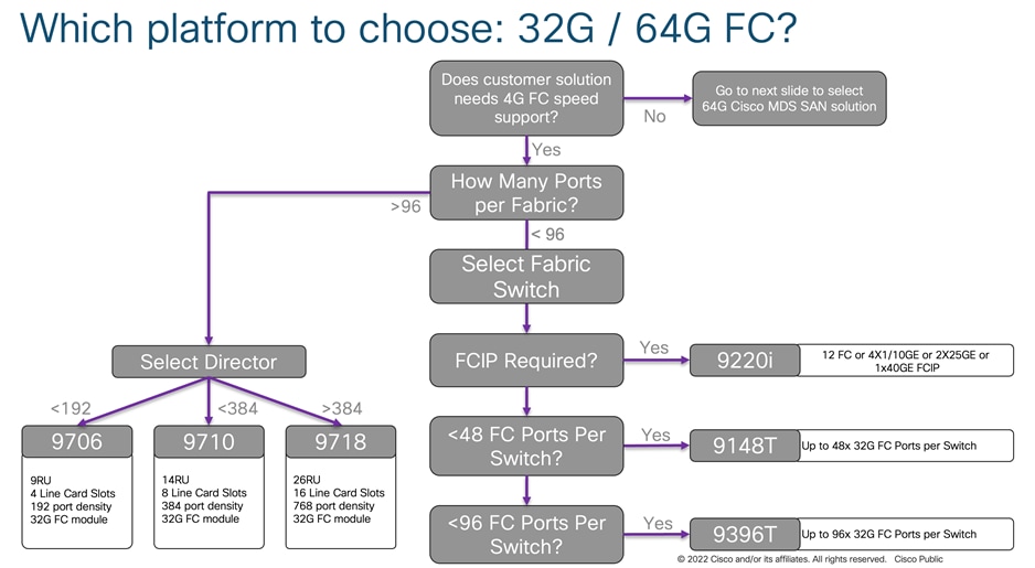
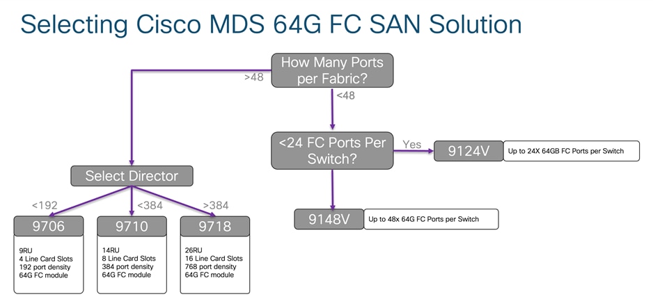
Depending upon the required physical FC port count, we can select the switch we need for our use case. As we discussed before in this paper, 32G FC fabric switches and 32G directors have similar feature capability like encryption, port group configuration, buffer credits per port group, maximum distance coverage over dark fiber using DWDM device. So, we have to select switch based upon the physical port requirement. If you are looking for FCIP connectivity option, use the table given below.
When migrating to a Cisco MDS 9000 family–based SAN, there are several migration methods: Remove & Replace, Cap & grow, and Interoperate. The choice of migration method is determined by several criteria, like how the new switches are going to be installed in SAN (new or existing one), risk mitigation needs, migration timeline, connectivity requirements, overall fabric capacity during the migration process, and whether you want a single-vendor or mixed-vendor operation.
Remove and replace
As the name suggest, with this approach you simply replace fabric-wide Brocade switches with preconfigured Cisco MDS 9000 Family switches. In almost all installations of SAN, we always have dual fabrics. Performing one fabric upgrade at a time will provide non-disruptive upgrade process, as second fabric will take over the load during migration window.
Cap and Grow
This process is ideal when customers are installing new storage fabrics, along with new server farms. In some cases, when customers want to clean up their older (legacy) hardware, they prefer to start from scratch. So, they purchase new storage arrays, along with new servers which will be connected to new Cisco MDS SAN switches.
Interoperate
In this process, Cisco MDS 9000 Family switches are connected to Brocade switches using interoperate mode (on Cisco MDS switches) in the fabric. Both vendor’s products work together for a brief period of time during maintenance window before the Brocade SAN switches are removed from the fabric.
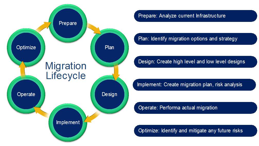
Migrating or upgrading SAN from one vendor to the Cisco MDS 9000 Family product line can be relatively easy if proper guidelines are followed. Explanations are included for some of these technical terms at the end of the paper, in the Appendix. For ease of migration, the migration process is divided into multiple steps, narrowing the change window required, focusing the tasks, and helping mitigate risk and ease deployment. These are the main steps:
Prepare
Analyze the current storage, server and switching infrastructure, business requirements, and risks. Identify critical servers, storage subsystems, servers and applications. Pay special attention to critical applications, still running on legacy infrastructure. Prepare a rollback plan in case rollback is required. Prepare or update the SAN and storage diagram to meet new requirements. Prepare all device configurations (zone conversion, VSAN configuration, etc.) in advance and have them readily available during the migration window. Depending on migration method used, most of the configuration can be done ahead of time.
Plan and Design
Identify migration options and create a migration strategy. Identify any new additions and future requirements for the SAN fabric at this stage. This step will require the SAN administrators to consider redundancy, flexibility, and future growth requirements to sustain this environment for the longer duration. Cisco best practices should be applied of fabric designing during this process to make it more resilient. When migrating from third party to a Cisco MDS9000 SAN, a new port layout (port-mapping, cable plan) needs to be document that considers high redundant design. In principle it must consider the members from E or F-port-channels across multiple modules. The same model should be also applied to storage and host ports. Whichever migration process will be chosen, we should always execute a dry run of our migration plan. This is an important step to make sure nothing is missed out on the actual day of migration. We can also verify / test our config and clean up our steps, to ease the actual migration process during this step. It is important to test this environment for key requirements from connectivity perspective, some of the application performance and before putting it into production. This will minimize any un-expected issues during actual migration window. Once testing is done, it’s time to move the new Cisco MDS 9000 switches in production.
Implement
Perform the actual migration by moving cables, connecting SFPs, and activating the final configuration of switches, verified in planning and design step. Connect the right SFPs as required by speed and distance, and activating the final configuration of switches, verified in previous step. Also, verify power budget required by SFPs received and make sure this is in the expected range. It is always a good practice to polish the cable before reconnecting it to the new MDS switch.
Operate
After the migration is complete, verify the migration at multiple points:
1. Application response time
2. Dual path redundancy check
3. Bandwidth utilization across fabric
4. Load balancing across port channel members
5. Resource utilization across the switches
We can use Data Center Network Manager (DCNM) or SAN Insights Discovery (SID) tool to perform above tasks.
Optimize
After migration is complete, as a best practice, you should implement continuous monitoring and optimization to identify and mitigate risk and tune the infrastructure to accommodate new projects and applications as the need arises. Following white papers have been published, detailing some of the best practices to operate and optimize Cisco MDS 9000 series–based SAN:
· Monitoring and Alerting in Cisco MDS Fabric White Paper
· Cisco MDS 9000 Family Diagnostics, Error Recovery, Troubleshooting, and Serviceability Features
The designing, planning, and preparation stages are very critical to a successful and painless migration. The better the design, in-depth planning, and preparation, easier the final implementation of the migration will be. Now, let’s go further deep into each phase.
Preparation
The process of SAN migration starts with preparation. This step will help us define, scale, and meet our end goals of high performing, resilient and redundant fabric, ready to meet our future requirements.
Inventory your network
Prepare a list of host enclosures, hosts, storage enclosures, targets, switches, optics, applications, hardware features currently implemented, software features currently in use, and firmware versions of everything. Everything that we can think of in our rack needs to be considered in this inventory, including optics, cables, length of existing cables, etc. Cisco’s NDFC SAN management software and SAN Insight Discovery (SID) tool can help you inventory your Cisco or Brocade fabric. We will discuss NDFC and SID tool in more detail later in this document.
Verify Compatibility
Verify your inventory with the software- and hardware-compatibility matrix and switch-interoperability matrix. Here is the interoperability matrix that Cisco maintains with some vendors: Cisco Data Center Interoperability Support Matrix. In the interoperability-matrix document, you will also find the vendors we support and have tested in our interoperability lab. The document includes links to other storage, server, and HBA vendors that you can reach out to for more details about their solutions. If you cannot find hardware or software features that you need help with, please connect with your Cisco sales team for further assistance.
Upgrade Components
You may need to upgrade a few components to meet the requirements of the support matrices. Upgrading will reduce the likelihood that incompatible hardware or conflicts with existing software will delay the migration process. You may have to upgrade the hardware and software on the list you prepared in the previous steps. Please make sure to
Assess the SAN
Before starting the migration, collect current metrics and future metrics requirements for proper assessment. The assessment should include anything and everything we can think of. E.g., current bandwidth consumption, actual port usage for each fabric, the speed they are currently running at, trunk / port-channel configurations, VSAN / logical SAN configurations. Statistics such as bandwidth requirements (based on existing and new needs) and projected growth for bandwidth, targets, hosts, etc., can help you gauge the right set of requirements. This step will help you avoid bottlenecks later in the migration process or in the immediate future, once the migration is done.
Validate Applications
To set Service-Level Agreements (SLAs), application validation is essential. You need to consider current and expected future latency or delays associated with growth. In addition, multipath connectivity is required for non-disruptive migration. If the multipath connectivity is broken, it may be disruptive for applications. Cisco Data Center Network Manager (DCNM) for SAN can help perform a dual path host redundancy check for each server or storage array. Multipathing checks can be performed at an OS level.
As a best practice, it is also desirable to do some pretesting to validate hardware or software upgrades to test application-level connectivity between the fabrics along with the intended initiator-target pairs. When required, this testing should also be conducted on important features and functions for any site-to-site replication, data mobility, etc. However, exhaustive feature and function testing is not always practical because it may require dedicated test ports in the production fabric and storage subsystems, but such exercise will boost confidence in the migration for the operation team.
The following information about the existing SAN network for each fabric will also help you define an appropriate migration plan:
● Total number of host and server ports
● Total number of storage (flash, disk, and tape) ports
● Total bandwidth requirements from the host edge
● Total bandwidth requirements from the storage edge
● Current oversubscription ratio from the host to storage
● Expected oversubscription ratio from the host to storage
● List of Brocade features in use
● List of various feature-based licenses in use
The planning and design phases involve both physical and architectural elements.
Physical Planning
Physical planning includes identification of space, cooling, airflow direction, power, Power Distribution Unit (PDU), cabling, and cable rack requirements. Different chassis from different vendors have their own set of requirements. More details about specific Cisco MDS 9000 Family chassis can be found in the individual data sheets. Some of the important hardware components that should be considered are discussed here.
Chassis Power, Cooling, and Airflow
For the new SAN switches, verify that you have the correct amount of AC and DC power for proper operation, correct power cord connectors, and PDUs along with Uninterruptible Power Supplies (UPSs) with the appropriate capacity. The Cisco site preparation checklist includes more information about power requirements in the technical specification sections of the respective hardware installation guides.
Power planning for the chassis requires information about the total number of power supplies in the chassis, the type of power source (AC/DC), etc. to achieve GRID redundancy. Cisco MDS 9700 Series Multilayer Directors support AC and DC power supplies in the same chassis. They also provide GRID level power redundancy. The chassis’ cooling characteristics and the proper spacing needed for airflow are important for efficient operation of the chassis. For Cisco MDS 9000 Family switches, the hardware installation guide provides details about the height, width, and depth of the chassis.
The Cisco MDS 9700 directors have a front-to-back airflow direction, whereas any of the Cisco MDS 9000 Series 32G Multilayer Fabric Switch family can be in either direction (port-side intake or port-side exhaust airflow). Customers can select the type of airflow required during the purchasing process. For more details about airflow direction, see the following table.
Table 2. Direction of Airflow
| Cisco chassis name |
Airflow direction support |
| Cisco MDS 9700 Multilayer Directors |
Port-side intake |
| Cisco MDS 9396T 32G FC fabric switch |
Bidirectional |
| Cisco MDS 9148T 32G FC fabric switch |
Bidirectional |
| Cisco MDS 9132T 32G FC fabric switch |
Bidirectional |
| Cisco MDS 9220i Multiservice fabric switch |
Bidirectional |
| Cisco MDS 9148S 16G FC fabric switch |
Port-side exhaust |
| Cisco MDS 9396S 16G FC fabric switch |
Port-side exhaust |
| Cisco MDS 9250i Multiservice fabric switch |
Port-side intake |
For more information, please refer to the hardware installation guides for each platform.
Architectural Planning
Architectural planning includes all design-related details, including network topology, cable diagrams, cabling techniques, cable management, power-plug connections and positions, cabling mechanisms for different chassis, PDU placement, air conditioning, air circulation requirements, and any future requirements. Architectural planning requires more information and analysis than physical planning, including information about:
● Power cable connections to the chassis (Some chassis have front-end, and some have back-end connections.)
● PDU connectors and types (high-voltage AC/DC, power cable connector types, etc.)
● Space for new hardware (form factors and rack unit size and depth)
● Cable-length specifications
● Air space requirement around the chassis for proper airflow
● Airflow direction of the new switches
● Placement of PDUs and power-cable connections for the chassis
● Console connections to the chassis
● Front-door placement and space required at the front of the chassis
● Space required for maintenance (for example, for pulling out the line card or replacing the fan tray in the Cisco MDS 9700 director chassis)
Port Planning (Mapping)
This is one of the very critical steps in migration. We should pay close attention to physical port mapping from each host to edge switch, each storage port to modular switch and ISLs between core and edge switch. After looking at the logs from existing SAN, we should be able to find how each host / storage ports are connected, the ISL connections between chassis, oversubscription ratio, etc. During migration, we can refine or work out a better way to map physical HBA connections to switch port. This is a key point as we will assign physical ports to HBAs and add them to selected VSAN to manage traffic between host and storage. The final assignment of physical port mapping will help us achieve our goal of efficient cabling and ease of troubleshooting in the future. Here are some of the ideas, considering some of the best practices as well to efficiently use the buffer credits and other port-level resources.
Vertical Port Assignment
Use first set of sequential ports on each module, to connect to storage ports. Last set of sequential ports on each module, to be used as ISLs or to host ports.
Horizontal Port Assignment
Use first set of sequential ports on first module to connect to storage ports, last set of sequential ports on last module to be used as ISL or host ports.
To help migrate Brocade SAN switching config to Cisco SAN switches, we have resource pool of various tools and methods.
Zone migration tool: This tool can convert the Brocade FOS based zoning config to MDS NX-OS based configuration. Anyone can download and use this tool.
SAN Insights Discovery tool: This is a very comprehensive tool for taking snapshot inventory of each fabric. Migration configuration is one part of this tool. This tool can provide comparable MDS part number, convert zoning configuration to NX-OS equivalent and also help us convert the non-zoning configuration as well to NX-OS format. This is a cloud-based tool where you generate fabric report using a standalone program and upload the generated report file to Cisco Cloud for further visibility and inspection. Though this is a cloud-based tool, it is fully secured, and the reports are accessible to the account owner. Account owner can than give selected access to anyone that needs to see it. SID tool can identify both - Cisco and Brocade switches and fabrics.
Now, let’s look at these tools one by one.
Zone Migration Tool
To migrate SAN from Brocade SAN switches to a Cisco MDS 9000 SAN switches, Cisco has provided a Windows-based utility to easily migrate the zoning configuration. The Cisco Zone Migration tool can be downloaded from GitHub or the Cisco.com software download page.
GitHub link: https://github.com/CiscoMDS/ZoneMigratorTool
Cisco software download link:
https://software.cisco.com/download/home/283453013/type/282088132/release/8.2.1
Using Cisco Zone Migration tool
The Cisco MDS zone-migration tool helps to convert Brocade zoning configuration to Cisco NX-OS–compatible zoning configuration. The zip file contains a small windows program along with a readme.txt file with additional instructions and information.
Here is the step-by-step process to convert a Brocade zoning configuration to a Cisco MDS NX-OS–compatible zoning configuration.
Topology: The sample lab topology that we will be using for better explanation of this tool.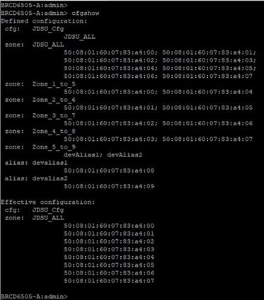
Step 1. Run “cfgshow” CLI command on principal (core) Brocade switch. Sample “cfgshow” file:
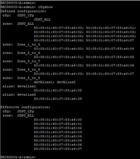
Step 2. Save output of “cfgshow” as a pure text file.
Step 3. Load the Zone Migrator tool that you downloaded from GitHub or Cisco’s download page.
Step 4. Point the Zone Migrator tool to the text file you saved in Step 2 (with Brocade “cfgshow” output).
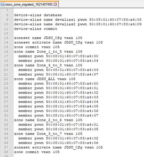
Step 5. Within a few seconds, it will generate a Cisco NX-OS equivalent zoning configuration file.
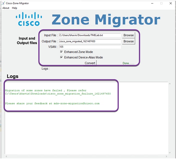
A sample NX-OS equivalent converted configuration file with zoning configuration. This tool will generate NX-OS compatible zoning configuration file saved in the output file path shown on the screen. At the same time, it will also show up any errors, it may have encountered during the conversion. e.g., any zones without any entries, any mis-match device alias mapping, etc. or anything that the tool may not have been able to parse or verify for any reason.
Step 6. Verify the zoning configuration text file. (You can also delete dead or extra or unwanted zones from this file.)
Step 7. Copy this zoning configuration on the Cisco MDS switch over CLI using the console or through an SSH/telnet connection through a management port.
Step 8. Give a final check to the configuration on the Cisco MDS switch.
Step 9. The Cisco MDS switch is now ready to take over as a core SAN switch in the production network.
Step 10. Place newly configured Cisco MDS switch in the rack and move the cables from Brocade to Cisco MDS switch.
Important Notes
1. Cisco Zone Migrator is a Windows-based utility, supported only over Windows 10 or Windows 7, 64-bit version.
2. The Windows workstation where you run the script should not have any pre-installed Python running on it. The program may give a runtime or library error if it finds any Python installation.
3. Ensure that the Brocade fabric switch is running Brocade Fabric OS v7.x.x or later.
4. Cisco Zone Migrator does not support domain-based or port-based zone conversion. If any zone member types are unknown in the Brocade configuration, please change them manually before taking the “cfgshow” output. If the tool finds any domain-based or port-based zoning configuration in the “cfgshow” output, it will create a log file with error messages for domain-based and port-based zone members.
5. During the conversion process, you can select enhanced zone mode or enhanced device-alias mode or both. This will help reduce payload sizes as the zones are referenced.
6. This tool will autogenerate and save the config with the filename: cisco_zone_migrated_<time-stamp>.txt in a predefined path, verified from the tool window.
7. The tool may also generate following files (in text format):
8. Cisco_Migration_log_<time_stamp>: Original Brocade config file
9. cisco_zone_migrated_<time_stamp>: NX-OS equivalent zone configuration file that can be used on MDS switches
10. cisco_zone_migration_failure_<time_stamp>: Error log of zoning configuration that could not be converted properly for any reason. This file will help us find any issues that happened during the zone conversion.
11. Now, configure Cisco MDS switch with management ip, and any other non-zoning related configuration (like AAA authentication, SNMP, Callhome setup, etc.).
12. If Brocade SAN has multiple FIDs (LSANs) / virtual fabrics, run this tool for each FID / virtual fabric in Brocade SAN, repeating above process. While converting for multiple FIDs, provide different VSAN numbers on Migration tool window. This will help you create a separate configs for each FID to individually separate VSAN on Cisco MDS switch.
13. Merge all of the NX-OS config files (cisco_zone_migrated_<time_stamp>), converted from each FID to single text file. This is the NX-OS config file for our new MDS SAN switch.
SAN Insights Discovery Tool
SAN Insights Discovery, or SID is another tool that we can use to help us with Migration. Note that only Cisco partners and Cisco employees will be able to see Migration tab in the SID tool, only when there is Brocade switch found in the fabric. The migration feature of SID tool works in the fabric with single Brocade FID. If the Brocade fabric has multiple virtual fabrics, this tool will not be able to help with migration / conversion. Here is the process to covert the Brocade configuration to Cisco NX-OS equivalent configuration file, in a single FID / virtual fabric:
● Download desired (windows / Linux) version of SID tool from https://www.cisco.com/c/en/us/support/storage-networking/san-insights-discovery/series.html#~tab-downloads
● Once downloaded, run the tool on respective platform. For this demo, we will use windows version of the tool.
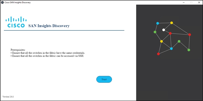
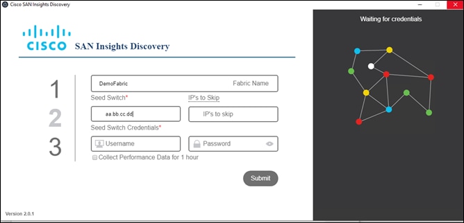
1. The starting page will look like this. Click on start.
2. Submit the login credentials from any one of the switches from your fabric.
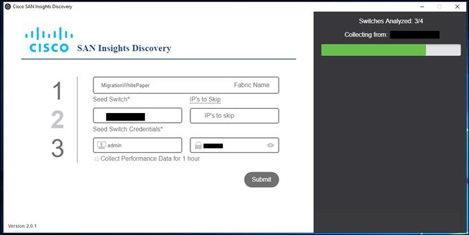
3. Click on Submit and it will start collecting configuration from all the switches in that fabric with same login credentials. If the login credentials are different for different switches, the switches with failed login credentials will not show up in the report. Those switches will show up in the error log file generated after the report is generated.
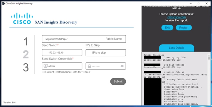
4. Once the tool is done collecting information from the switches, in the same fabric, it will save the file in selected path. If we click on More details tab at the right corner-bottom of the page, it will list all the “show” commands that it has run on switches and, filenames it has generated.
5. Now create login on https://csid.cisco.com and login to the site.
6. Once logged in, click on upward pointing arrow to upload the file from your computer. Within few seconds, SID tool will analyze the report.
7. Now select/click on report. We will see a menu at the top and one of the tabs on the right side is “Migration”. Note that “Migration” tab is visible only to Cisco partners and Cisco employees. If you are end customer and need help, please ask your account team.
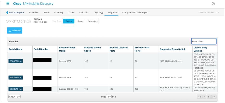
8. Under Migration tab, there are three sub-menus: Switch, Zones and Parameters.
9. Switch tab will provide details of Brocade switches, FOS release, switch model, total ports, port licensing, etc. and comparable Cisco switch options. Suggested “Cisco Switch” and “Cisco Config Options” will provide comparable Cisco MDS switch and modules. This will help prepare right proposal for any customer, moving from Brocade SAN switches to Cisco MDS switching platform.
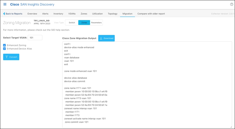
10. Zones tab will provide zoning configuration option. Enable “Enhanced Zoning” and “Enhanced Device alias” option (recommended). Select target VSAN and it will convert the Brocade configuration to Cisco NX-OS equivalent configuration in the window.
11. Select Target VSAN number (1-4093) that you would like this new zoneset to reside.
12. Select optional features:
13. Enhanced Zone Mode
14. Enhanced Device-Alias Mode
15. Click on the “Convert” button to generate the output file that can then be applied to the MDS 9000 switch. The file will generate the new Cisco zoning information.
16. Download the migrated zoning output
17. Verify the zoning configuration. We can do zone cleanup if needed (removing dead zones / WWNs).
18. Login to Cisco MDS Switch and copy-paste the output from above step to MDS switch.
19. Parameters tab will help us extract all the non-zoning configuration like AAA, SNMP, LDAP, etc. Click on download tab to download this in NX-OS equivalent format.
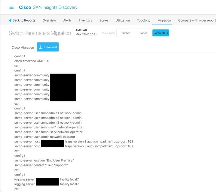
◦ Click on Parameters tab and it will show you the rest of the non-zoning configuration.
◦ Download the file by clicking on down arrow.
◦ Open the download config file and copy-paste it to Cisco MDS switch.
Once you have the configurations, we can follow the remove and replace migration strategy to perform fabric-wide non-disruptive migration.
Above options provide multiple ways to convert Brocade FOS based configuration to equivalent NX-OS equivalent configuration.
Operate and Optimize: A Continuous Cycle
After the migration process is complete, perform the following actions to verify that the migration was successful:
● Run a Cisco DCNM SAN dual-host path redundancy check report to verify that all hosts and storage devices have redundant paths.
● Check application performance levels and servers for path redundancy to verify that defined and expected SLAs are being met.
● Back up new SAN configurations (on Cisco MDS 9000 switches) so that they are available in the event of a failure.
● Back up switch configurations regularly to protect against unexpected outages. You can run a script at a scheduled time to back up configurations to a Secure FTP (SFTP) server, or you can use Cisco DCNM to back up configurations in the Cisco DCNM database.
After the migration is complete, we need to keep the network optimized and run it with optimal efficiency. Cisco DCNM for SAN has features that can help optimize the network.
Cisco DCNM topology discovery is an inherent capability of Cisco DCNM for SAN to accurately depict the current topology and the device state of the connected fabric. This topology discovery also maps end storage and host devices and older switches discovered in the fabric - a very handy capability during migration.
The following table lists some of the Cisco NDFC for SAN software features available to help you optimize and operate a new fabric.
Table 3. Cisco NDFC for SAN features
| Feature |
Description |
| SAN Analytics |
The SAN Analytics solution provides insights into your fabric by allowing you to monitor, analyze, identify, and troubleshoot performance issues. |
| Slowdrain monitoring |
The Slowdrain monitoring template can help detect, troubleshoot, and automatically recover from the slowdrain situation. |
| Port Monitoring |
Using Port Monitoring, we can configure various counters on ports to monitor them for any unexpected behavioral issues. |
| Template configuration |
Using the Cisco DCNM web client, you can monitor Cisco MDS 9000 Family and Cisco Nexus® Family switch events, performance, and inventory, and perform minor administrative tasks. |
| Summary dashboard |
Get information about data center switches, selected SAN and LAN switches, or a group of LAN and SAN switches to see their current status, licensing details, host topology and events, and storage device topology and events. |
| SAN discovery and topology mapping |
Cisco DCNM for SAN provides extensive SAN discovery, topology mapping, and information viewing capabilities. It collects information about the fabric topology through Simple Network Management Protocol (SNMP) queries to the switches connected to it. Cisco DCNM for SAN re-creates a fabric topology, presents it in a customizable map, and provides inventory and configuration information with multiple viewing options. |
| Inventory management |
The Information pane in Cisco DCNM for SAN shows inventory, configuration, and status information for all switches, links, and hosts in the fabric. Inventory management information includes vendor names and models and software and firmware versions. Select a fabric or VSAN from the Logical Domains pane and then select the Summary tab in the Information pane to get a count of the number of VSANS, switches, hosts, and storage elements in the fabric. |
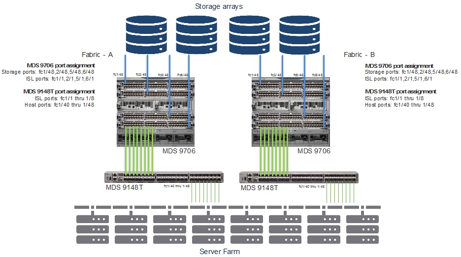
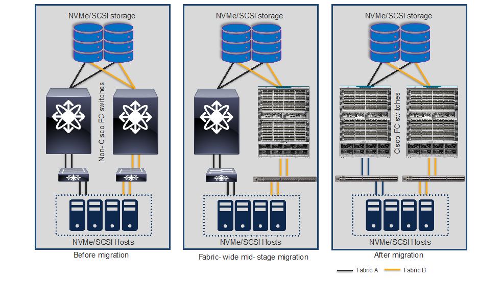
SAN best-practices typically call for two fabrics for redundancy, referred to as Fabric A and Fabric B in this document. There are several migration options, but the two methods discussed here are the preferred ones.
Note that irrespective of which migration method we use, we have to make sure of below things before starting migration process for non-disruptive migration.
Pre-migration checklist:
1. Multipathing is must between every host and storage port.
2. Verify VSAN configuration on servers, hosts and existing SAN switches
3. Host path redundancy check should be at application level to avoid any application outage.
4. Each fabric should be able to handle load of both fabrics during migration window. Note that when we perform fabric wide migration, both fabrics will be taking turn to alter load on each other. We can use SAN Insights Discovery tool to verify the load on each fabric.
Remove and Replace Migration Strategy
The remove-and-replace approach to migration is also called fabric-by-fabric replacement. The advantage of this option is that the migration process takes very less time to complete, and we avoid interoperability challenges while replacing Brocade switches with Cisco MDS 9000 Family switches on a per-fabric basis.
With this option, Fabric A hardware will be replaced while Fabric B remains active and takes over the full load of Fabric A, providing redundancy and reduced downtime (if any). As a best practice, we should disable the host and target Host Bus Adapters (HBAs) connected to Fabric A prior to the migration, to avoid any impact on applications. After the Fabric A hardware is replaced and verified to be up and running, all host and target connections to Fabric A are reenabled. After verification that server-to-target operation is restored over Fabric A, we repeat the same process on Fabric B. The conversion of Fabric B can occur in the same change window or in a subsequent change window at a later date, depending on user requirements.
Before we start this migration process, we have to make sure our secondary fabric is capable of taking over the load of primary fabric, in addition to its own workload. Because we will have one active operational fabric, carrying over workload of two fabrics during the migration window.
Migration Steps Using Remove and Replace Strategy
Original Setup Using Brocade Core and Edge FC Switches
Replacing Brocade switches in Fabric-A
Step 1. Download cfgshow CLI output from principal Brocade switch of the fabric. If the fabric has multiple Fabric-IDs (FIDs / logical SANs), please download configuration from each FID separately.
Step 2. Download and run Cisco Zone Migrator tool from the links provided earlier in this document.
Step 3. Convert the Brocade zoning configuration to Cisco NX-OS equivalent zoning configuration, for each FID/LSAN from Brocade environment.
Step 4. Merge all NX-OS equivalent / converted configuration files into a single text file. NX-OS configuration files can be viewed using any text editor.
Step 5. We can also do-little housekeeping on the converted file by cleaning up the zoning configuration (removal of dead zones, deleting un-necessary zones, orphan zones / wwns and verifying the newly converted configuration, if needed. Now you have single NX-OS equivalent zoning configuration, in a text file.
Step 6. Stage the new Cisco MDS switch in the staging area.
Step 7. Connect the console cable and power ON the switch. The switch will launch the Cisco NX-OS setup utility using interactive CLI guide for basic configuration of system. The information needed for initial configuration checklist can be found here: Initial Setup Checklist for Cisco MDS SAN switches.
Step 8. Run above step for all fabric / edge switches as well.
Step 9. Upgrade (or downgrade) the NX-OS software, if needed.
Step 10. Copy the NX-OS converted configuration from above step to new Cisco MDS switch. You don’t have to configure every Cisco MDS switch in the fabric. Just configure one switch that is going to be your principal switch in the fabric.
Step 11. Configure additional configuration parameters like SNMP alerts, call-home alerts, LDAP/AAA authentication, or any non-zoning related configurations, etc.
Step 12. If there are multiple Cisco MDS switches (directors and/or fabric switches) in the fabric, perform step 8, above, on all of them.
Step 13. Copy the converted zoning configuration from step 3, above, to the Principal (core) MDS switch in the fabric. Principal switch is the one with highest fcdomain priority. Priority 1 has the highest priority.
Step 14. The core Cisco MDS switch is now ready to be moved to production network. Move the switch to production racks and connect additional top-of-rack or edge switches, hosts and targets to this core MDS switch. Once the principal switch identifies all the switches in the fabric, it will show up the topology from switch CLI or in DCNM topology view.
Step 15. If the fabric switches are in NPV mode, they will not perform any zoning functionality. We can enable the NPIV feature in switches if we want them to do participate in zoning activity.
Step 16. The principal switch will auto populate the zoning configuration across all of the other member fabric switches.
Step 17. Verify that the host and the storage ports can log into the new Cisco MDS switch(es) and that the ports are in the correct VSAN and part of the correct zone and zone set. Also verify application connectivity through both paths.

SAN topology after Fabric-A migration
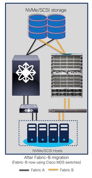
Replacing Brocade Switches in Fabric-B
Follow the same process explained above to migrate the path(s) from the second fabric’s Brocade switch(es) to the new Cisco MDS switch(es) once everything is verified and running smooth in the new active fabric.
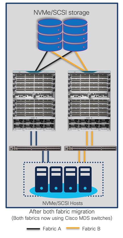
The final topology will look like below.
Final topology (after migration) using Cisco MDS 9000 Family switches
SAN topology after Fabric-A migration
Advantages and Challenges in Remove and Replace Migration Strategy
Advantages
● Minimal risks as the configuration are verified before it is loaded in new switch.
● Resources can be optimized (TCAM, CPU, etc.) as we clean up the config, before putting it on new switch.
● Quick migration, the only time required is re-cabling to new switches. The new switches can be positioned, configured before putting the migration window.
● Tools like Zone migration tool, SID tool can help convert the configuration to Cisco NX-OS format.
● Multi-phase migration is possible (Refreshing one fabric at a time)
● Interop mode configuration is not required, reducing complexity.
● Can be performed in green field or brown field deployment.
● Safer rollback, if needed
Challenges
● Need multi-vendor expertise
● Multipath is a must
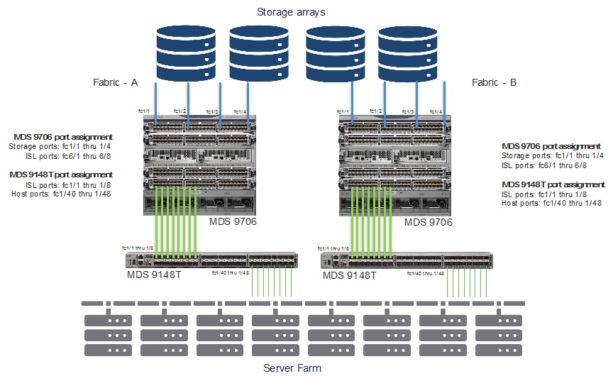
Cap-N-Grow Migration Strategy
Cap-N-Grow strategy is preferred one if we have green-field deployment of our storage, server and SAN together. With the cap-N-grow method, a completely new storage environment setup is created using new Cisco MDS 9000 Family switches. After the new infrastructure is built, we can start adding our existing server and storage devices to the Cisco MDS 9000 Family fabric. This method is appropriate when we are deploying a new application environment or upgrading a large number of storage devices. We can start with one director-class switch and end up swapping the whole SAN infrastructure fabric during the scheduled change window.
Here is a step-by-step guide to apply this strategy. Existing topology is shown as below.
Migration Steps Using Cap-N-Grow Migration Strategy
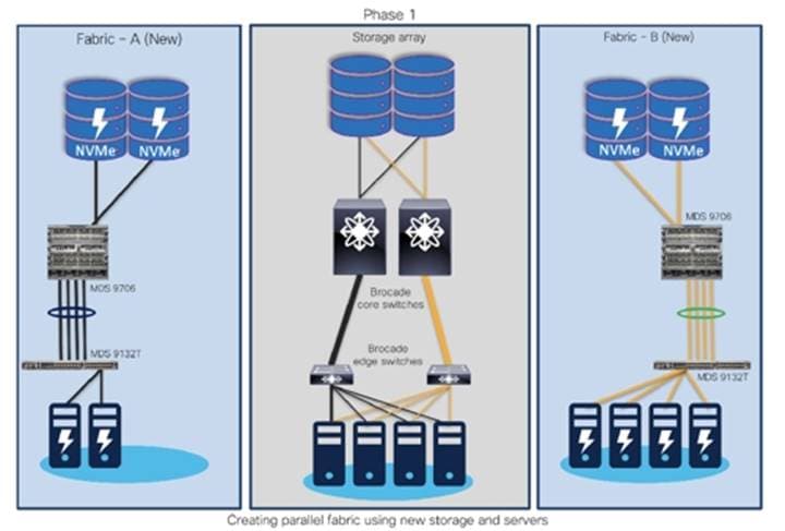
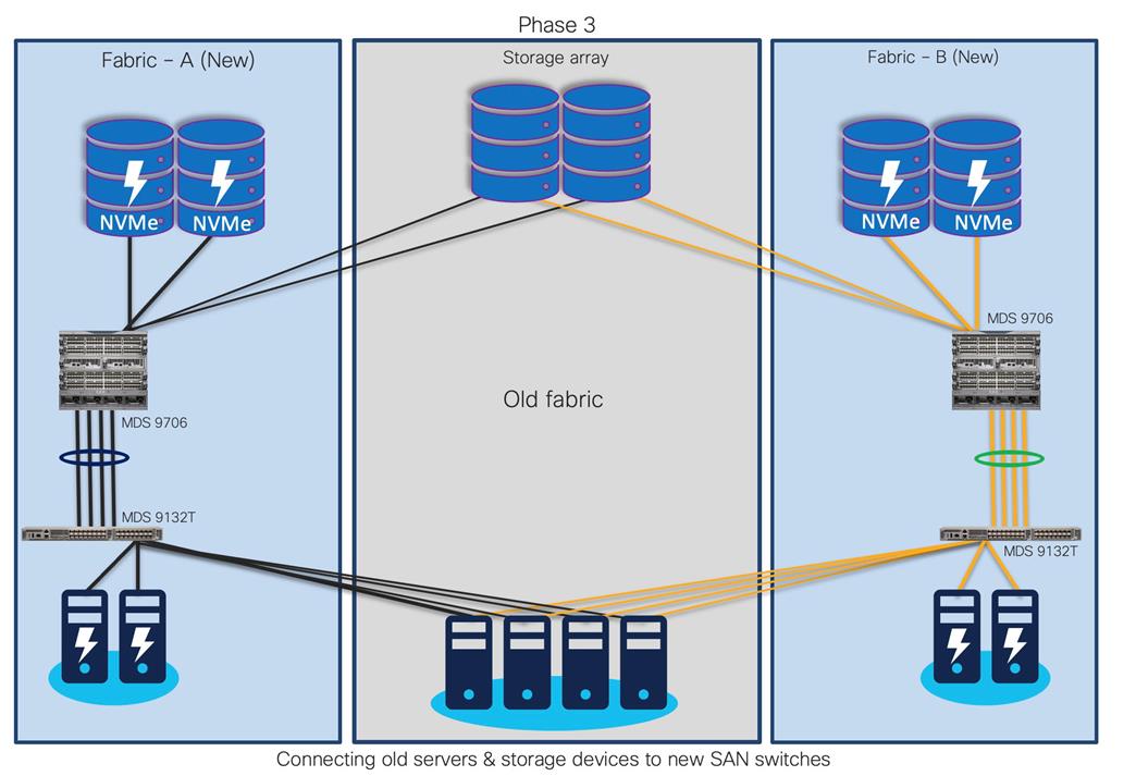
Step 1. For example, with Fabric A and Fabric B in production, start building completely new Fabric A (New) and Fabric B (New). Deploy new storage and hosts in Fabric A (new) and Fabric B (new) as shown below.
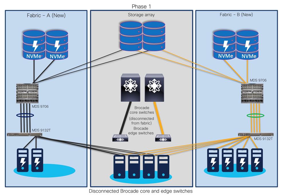
Step 2. Once Fabric A (new) and Fabric B (new) are operational, start migrating existing host and storage ports from Fabric A and Fabric B to Fabric A (new) and Fabric B (new), respectively.
Step 3. Now, decommission the (old) Brocade core and edge switches.
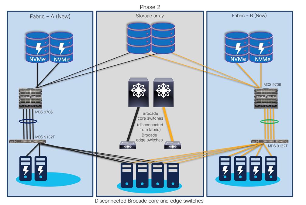
Step 4. Your new fabric will look like this, old storage, and servers (if required) are moved to new Cisco SAN switches.
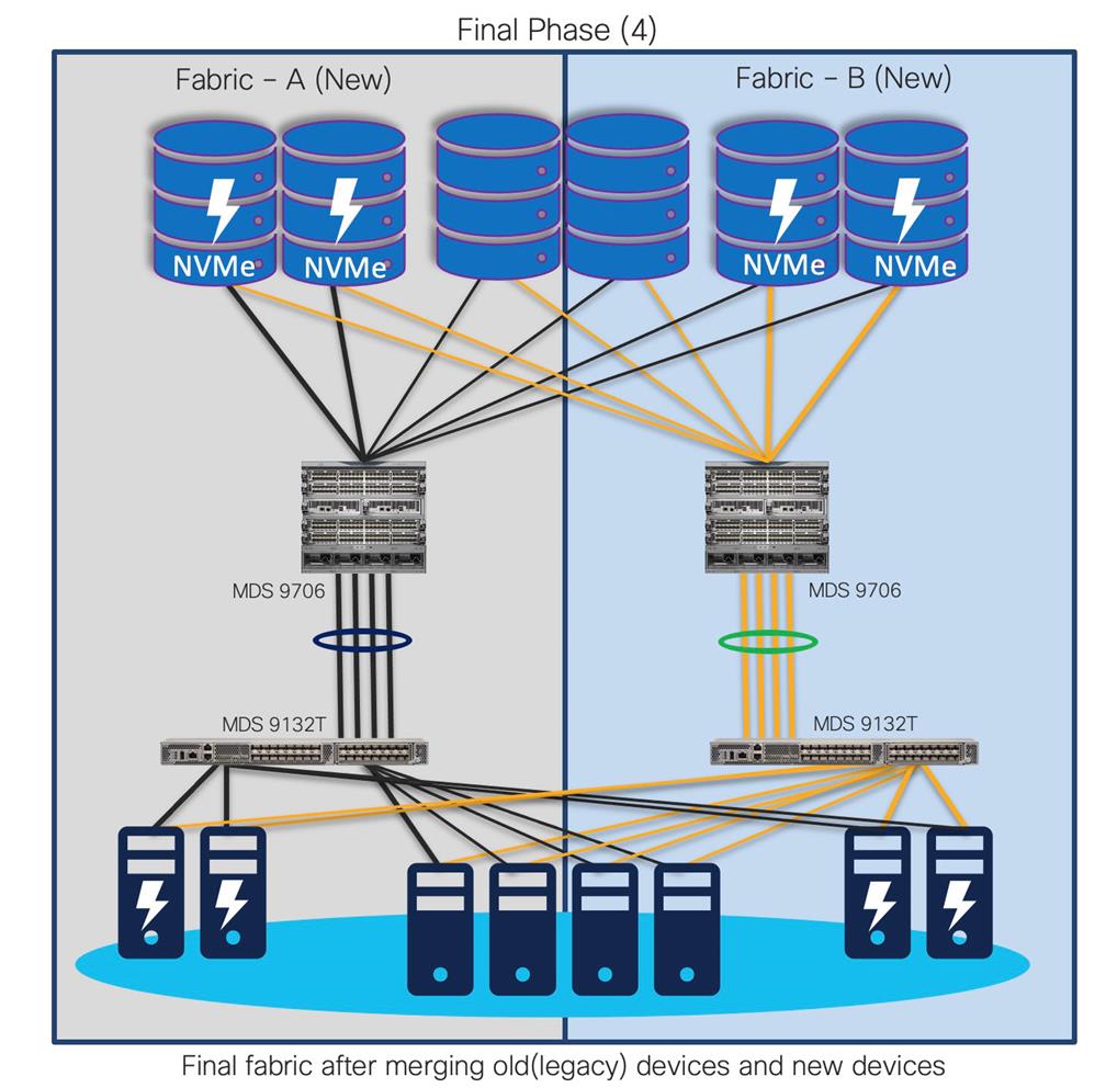
With old switches decommissioned, the new fabric has much more enhanced security, improved performance, and resource utilization. This approach provides continuity for the business along with room to expand the infrastructure. It also reduces interoperability risks and migration complexity and provides the flexibility to roll back the changes in the event of any emergency situation. In this type of migration, the Cisco MDS 9000 Family switches are introduced in parallel with the existing SAN infrastructure.
Advantages
● Allows phased migration
● Preferred for Green field install base
● Pay as you go model
● SAN administrators have time to learn new environment
● Less risks
● Interop mode configuration not required
● Minimal downtime
● Safer rollback, if needed
Challenges
● Multiple vendor SAN exists for longer time
● Two parallel infrastructures could be running during migration
● May need additional hardware (hosts, storage devices, ports, etc.)
● May require added infrastructure support (rack space, power, colling, cabling, etc.)
Interoperate Migration Strategy
Interoperate migration method is another possible way of migrating Brocade config to Cisco MDS config non-disruptively. In this migration method, the Cisco MDS9000 switch is integrated into Brocade SAN environment. Then, slowly, the storage traffic is transferred to the Cisco MDS 9000 Family switches one switch, one application, and one blade chassis at a time. Cisco MDS 9000 Family SAN switches can interoperate with Brocade SAN switches and can offer better scalability and capabilities.
With this approach, more time is needed to complete the entire migration process. The timeline can stretch from a few hours to a few months, depending on the size of the SAN infrastructure, hardware, and software-compatibility verification of all components in the fabric, etc.
Interoperate Migration Process
Now, let’s look at the step-by-step guide of what happens in this process. We will walk through one of the common topologies and actual migration with step-by-step instructions. Here is a sample topology that we will use to explain the migration process using interoperability mode.
The goal is to replace core FC switch - Brocade G620 with Cisco MDS 9706, non-disruptively. In the end, MDS 9706 will be FC core switch, connected to Brocade 6510 (acting as edge switches). Given below is the generic basic process of interoperate migration. This process might vary depending upon any environmental / feature requirements.
Note:
● Brocade G620 is our core/principal switch
● Brocade 6510s are our edge switches, with NPIV feature enabled.
● Brocade 6510s are connected to G620 using ISLs (port 30,31) and Cisco UCS hosts on the other side (port 1,10).
● All Brocade switches are running FOS 8.2.1c version
● Brocade switches are connected to UCS servers and generic storage arrays.
● The servers are running VMware ESXi 6.7 version with Redhat Linux and Windows VMs.
● Cisco MDS 9706 is running NX-OS 8.4.1(a) software release.
● Cisco MDS 9706 director chassis is using 48-port 32G FC module for connectivity to Brocade G620, Brocade 6510 and storage arrays.
This is a generic process, remains valid for any Brocade switch as core, being replaced with any Cisco MDS 9000 series switch. There might be some additional steps needed, depending upon the topology, feature requests, etc. but migration process / approach will remain mostly same for any interop-based migration from Brocade SAN switches (director or fabric switches) to Cisco SAN switches (director or fabric switches).
If you have any specific requirements outside of this topology or scope, please contact your Cisco sales team and work with engineering to help with interoperability validation.
Before we start the process, let’s verify the platform information.
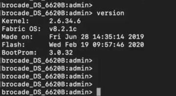
Brocade G620 switch FOS version details:

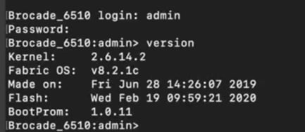
Brocade 6510-A / 6510-B version details:
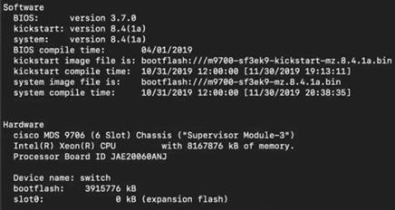
Cisco MDS 9706 version details:
Now, let’s look at the zoning configuration on Brocade switches.
● We have two target (storage) ports and four initiator (server) ports in total. Two initiator ports on each 6510s, are connected to each server to with redundant path.
● Ports 30 and 31 from 6510s are connected to G620 port 30 and 31 as E ports (ISL).
● Ports 32 and 33 from G620 are connected to storage device.
Port connectivity on Brocade G620:

We will configure management IP address, and additional initial configuration using initial quick setup wizard. There is no need to do any additional configuration as of now.
Cisco MDS 9706 is a new switch, and is not yet connected to any fabric, there will be no zoning configuration on this device.
Cisco MDS 9706, will only have default VSAN (VSAN1) in default mode without any zoning configuration, as shown below:
Zoning configuration on Cisco MDS 9706:
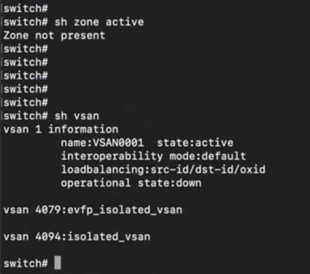
Now let’s start interop mode-based migration process.
Migration Steps Using Interoperate Migration Strategy
Step 1. Create a new VSAN (VSAN 100) and put it in interop mode 3 on MDS 9706 switch.
Step 2. Configure interface fc5/1 with speed auto and mode “E”, enable interface and add assign fc5/1 to VSAN 100.
Configuring interface and VSAN on MDS 9706:
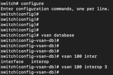

Step 3. Enable port 2 on Brocade G620.
Enabling port on Brocade G620:
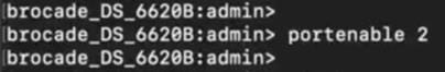
Step 4. Once we enable the interface, it will come up in “E” mode with ISL connection to Port 2 of G620.
Verification of interface 5/1 on MDS 9706, connected to port 2 on Brocade G620:
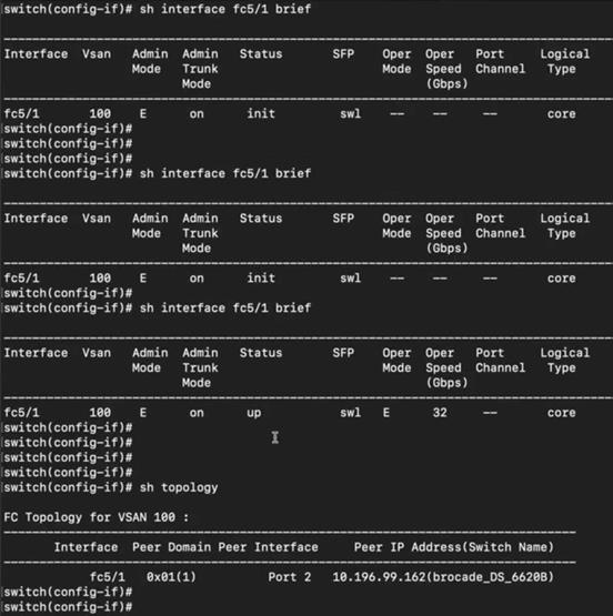
Step 5. Now verify zone database on Cisco MDS 9706 and BRCD G620 switches. We will see the zoning configuration getting populated from Brocade G620 (port 2) to MDS 9706 via ISL (interface 5/1) on MDS 9706.
Zone database on Cisco MDS 9706 (after ISL connection to G620):
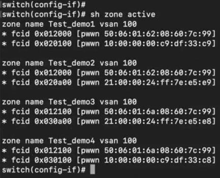
Zone database on Brocade G620 switch (after ISL connection to MDS 9706):
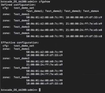
Step 6. show fcns database will also provide details of FCIDs and PWWN Mappings in the fcns database on MDS 9706. FCNS database was automatically built after connecting ISL between Brocade and MDS switches (previous step).
FCNS database verification on MDS 9706:
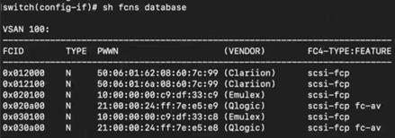
Step 7. Run portperfshow command on G620, to verify ports 30, 31,32, and 33 are showing performance statistics (and passing traffic):
Verifying port performance on Brocade G620:
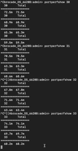
The topology at the end of this stage will look like this:
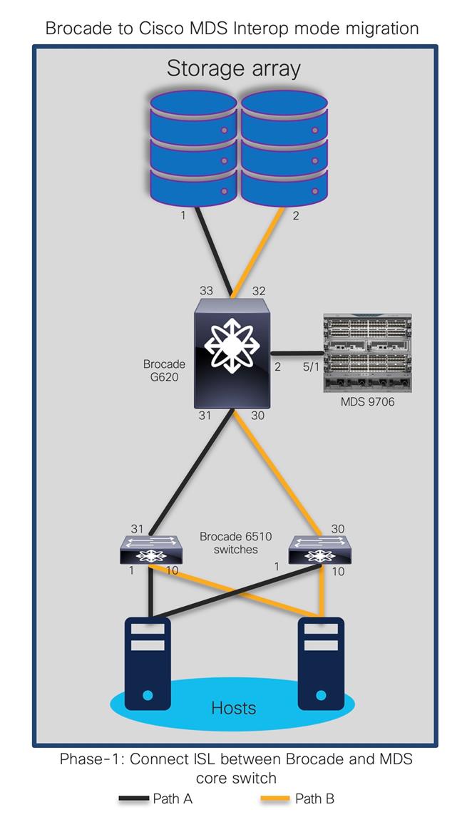
Phase 2: Moving first storage port from BRCD G620 to MDS 9706
In this stage, we will move one of the storage ports connected to G620 (port 32) to MDS 9706 switch (interface 6/32).
The updated topology at the end of this step will be like:
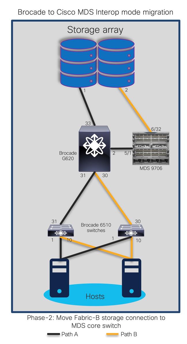
Step 8. Disable port 32 on BRCD G620.
Disabling port on Brocade G620:
![]()
Step 9. Verify that traffic is now passing thru port 33 on Brocade G620 using CLI command – portperfshow. This is to make sure the connectivity between storage and host ports remains active thru secondary path.
Step 10. Now, move the storage port cable from port 32 on Brocade G620 to Cisco MDS 9706 port 6/32.
Step 11. Enable port fc6/32 on MDS 9706, configure speed and mode, put it in same VSAN 100. it will show up in FCNS database after successful connection to storage port (previously connected to Port 32 of BRCD G620).
Enabling and configuring interface on MDS 9706:

Step 12. Verify the zone database on MDS 9706 and Brocade G620 to make sure storage port (60:7c:99) is back in active zone on MDS 9706 and Brocade G620.
Zoning configuration on Brocade G620 after moving first storage port to MDS 9706:
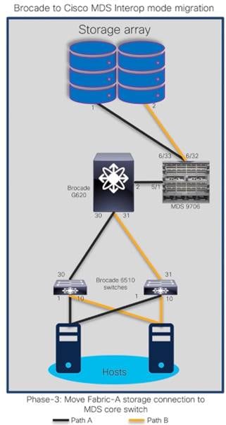
Step 13. Verify traffic / performance statistics on port 6/32 of MDS 9706. The incrementing numbers on the ports show that port 6/32 on MDS 9706 is now passing traffic to and from storage port:
Verifying interfaces on MDS 9706, after moving first storage port to MDS 9706:
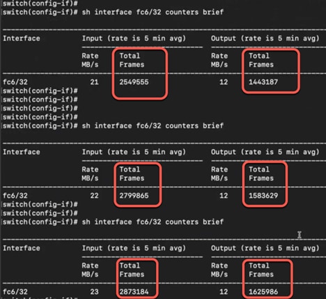
Phase 3: Moving second storage port from BRCD G620 to MDS 9706
Now, let’s move second port between storage array and BRCD port 33 to port 6/33 of Cisco MDS 9706 switch.
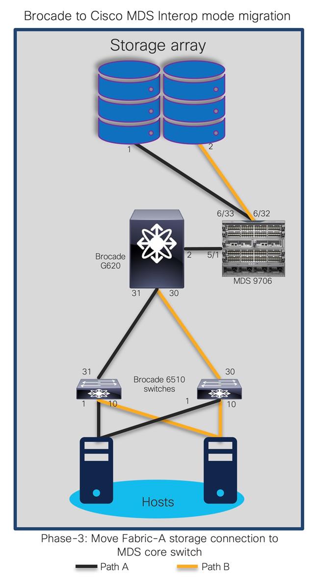
Step 14. Enable second interface fc6/33 on MDS 9706, set switchport mode to “e” and add the interface to VSAN 100.
Enabling and configuring second interface on MDS 9706:
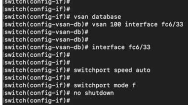
Step 15. Verify fcns database and zone database to make sure interface 6/33 is active on MDS 9706.
Verifying fcns database on MDS 9706 for newly configured port:
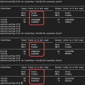
Step 16. Verify counters on interface fc6/32 and 6/33 to make sure they are passing traffic. These statistics will help us make sure the traffic is now flowing through MDS 9706 fc 6/32 and fc6/33 interfaces.
Performance verification on MDS 9706 switch interfaces:

Step 17. Show topology on MDS will showcase BRCD G620 still connected to the fabric via interface fc5/1.
Verifying Brocade G620 connectivity to MDS 9706:
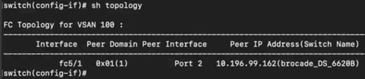
Phase 4: Moving Brocade 6510 (Edge switch) ports to Cisco MDS 9706
Now, we will move ISL connection between BRCD 6510 to G620 (port 30) to BRCD 6510 and MDS 9706 (fc6/30). The topology at the end of this step will look like:
Step 18. Disable port 30 on G620 and move the cable to port fc6/30 on MDS 9706. Enable interface fc6/30 on MDS 9706.
Disabling port 30 on Brocade G620
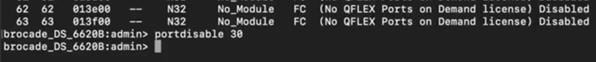
Step 19. Enable port fc6/30 on MDS 9706, setting switchport mode to “e” and putting it in VSAN100.
Enabling and configuring interface on MDS 9706, connected to Brocade edge switch (6510):
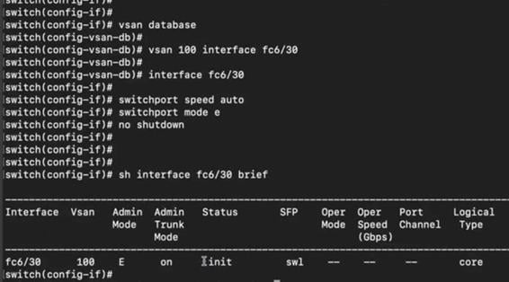
Step 20. Verify topology, port connectivity between Cisco MDS9706 and Brocade 6510:
Verifying interface statistics on port connected to 6510 edge switches:
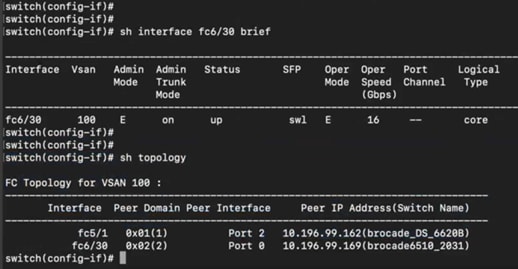
The topology at the end of this step will be like:
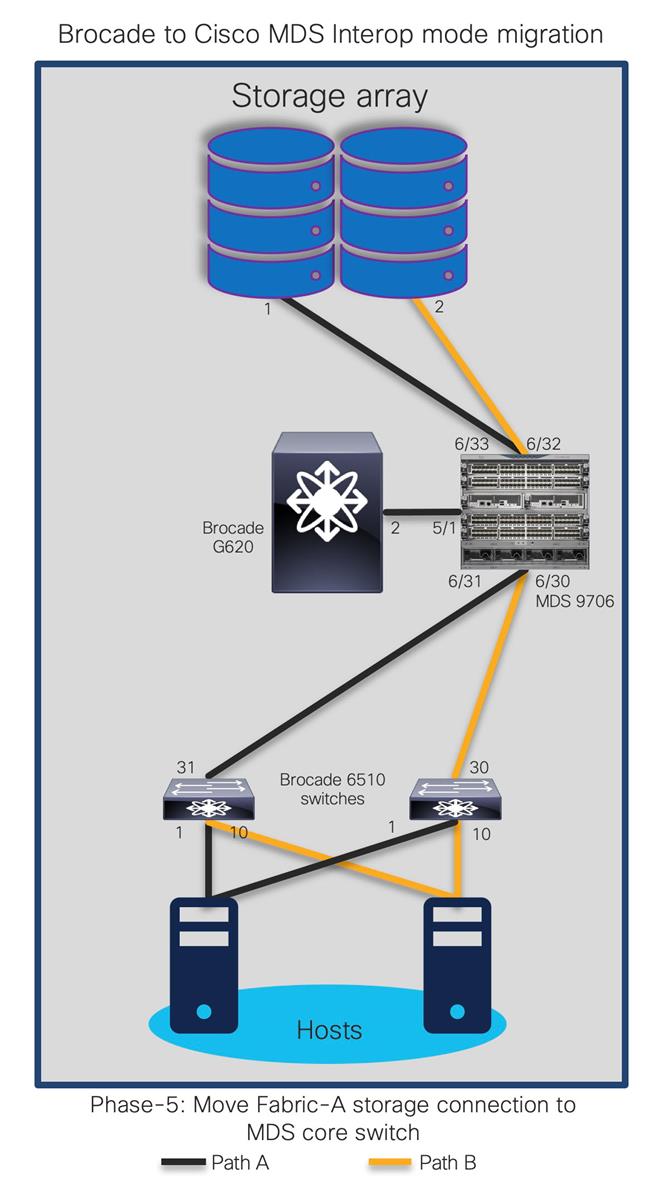
Step 21. Now move second ISL from G620 port 31 to MDS 9706 switch interface fc6/31.
Disabling port on Brocade G620, connected to 6510 switch:
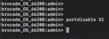
Step 22. Configure and enable interface on MDS 9706 fc6/31. Put interface fc6/31 to VSAN100.
Enabling and configuring interface on MDS 9706, connected to Brocade edge switch (6510):
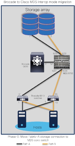
Step 23. Verify the topology on MDS 9706. It will list all three BRCD switches and interface counters on MDS 9706 (two storage ports (fc6/32,6/33) and two ISL ports (fc6/30,6/31) to 6510s. They should all be up and running.
Verifying ports and its performance on MDS 9706 (to storage and edge switches):
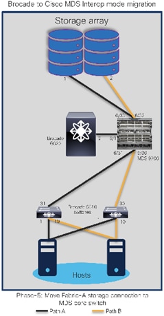
The topology at the end of this phase will look like:
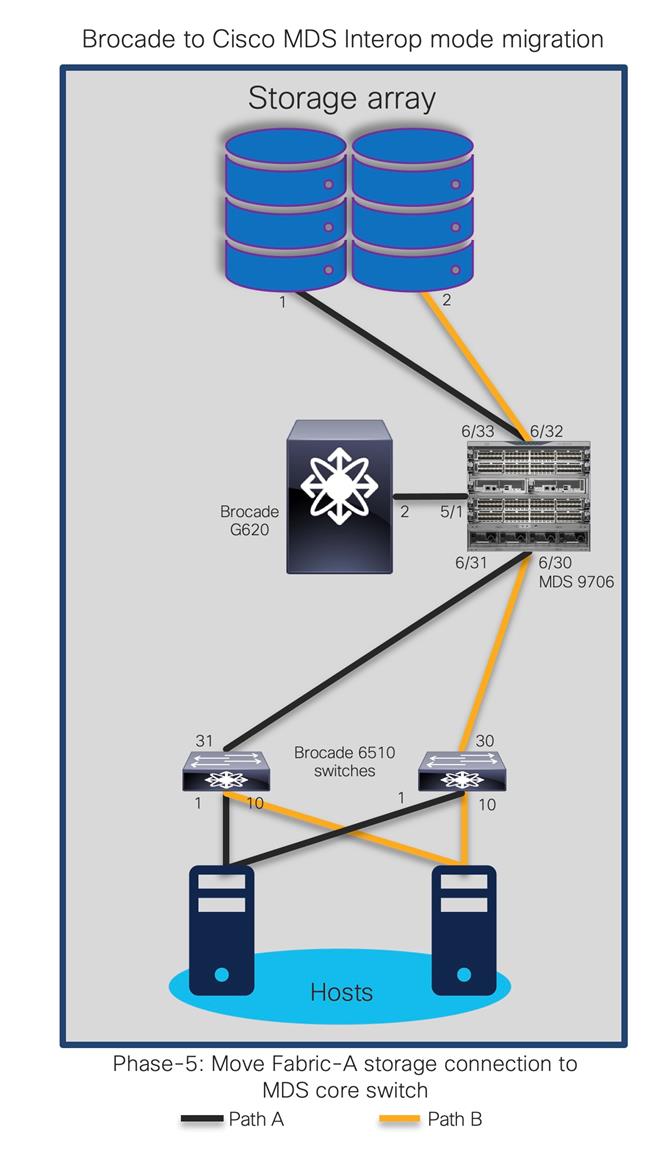
Step 24. Shutdown ISL between MDS 9706 (interface 5/1) and G620 (interface 2).
Disabling interface on MDS9706, connected to Brocade G620:
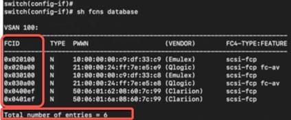
Step 25. Check the FCNS database and verify FCIDs on MDS 9706 and respective 6510s to make sure everything is configured properly.
Verifying fcns database on Brocade 6510 edge switches:
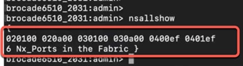
Verifying fcns database on Cisco MDS 9706 core switch:

Our new topology with MDS 9706 connected to 6510s using ISLs and storage ports should look like this:
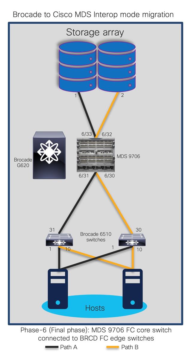
On MDS 9706, storage ports are connected to MDS 9706 and hosts are connected to 6510s. Note that we are still running BRCD 6510s (in switch mode) with MDS 9706 in the same fabric.
At this moment:
● Creating / modifying zoning configuration from either 6510 or MDS 9706 will now work, as both switches are participating in zoning activity (NPIV feature enabled).
● If Brocade fabric has multiple FIDs (Logical SANs), we have to create multiple VSANs in interop mode to populate the zoning configuration on MDS 9706.
● Enable IVR to allow communication between multiple VSAN in MDS 9706.
Advantages and Challenges with Interoperate Migration Strategy
Advantages
● Cisco MDS 9000 Family switches are immediately integrated into the existing SAN, allowing immediate port expansion.
● Adding Cisco MDS 9000 Family switches to existing Brocade fabrics is non-disruptive.
● Inter-VSAN Routing (IVR) can be used on Cisco MDS 9000 Family switches to reduce fabric merge risks.
● No downtime is required to connect the Cisco MDS 9000 Family switches to the fabric. You can migrate at your own pace but during migration window.
● Cisco MDS 9000 Family switch interoperability mode affects only the configured VSAN; all other VSANs are unaffected.
● Cisco MDS 9000 Family switch Trunking-E (TE) port can simultaneously carry multiple VSANs that are running in any interoperability modes.
● No configuration changes are needed on Brocade switches if they are already set to native mode.
Challenges
● As a best practice, this mode should be used temporarily during a migration maintenance window only.
● Vendor specific features like port cannel/trunking, slow drain and congestion avoidance, advanced zoning, etc. cannot be applied across the multi-vendor fabric. If applied, it remains within the vendor switching environment only.
● Multivendor switches interacting in the same fabric can result in unknown issues. The troubleshooting can be painful as it becomes a multi-vendor environment.
● Firmware upgrades and downgrades on the Brocade switches, Server or storage HBAs may be required to allow interoperability.
● Legacy HBA or their drivers may have to be replaced as it may not work with new hardware and software of Cisco SAN switches.
● Multi-vendor expertise is required as Cisco DCNM, management platform for MDS SAN switches cannot manage or monitor Brocade SAN switches or vice versa. We may end up managing both vendor SAN switches, separately.
● Redundancy is reduced drastically as port aggregation Trunking / Port Channel) is not allowed between Cisco and Brocade SAN switches.
● Operational and administration of fabric also gets challenging if any performance issue arises as both switches have different architecture, different scalability and port configurations.
● One storage port can be used by multiple hosts and applications, so the movement of one storage port may affect multiple storage ports, applications, and hosts (a situation known as a spider web).
● If you are connecting Cisco Unified Computing System™ (Cisco UCS®) servers to Brocade switches with no VSAN, the Cisco UCS SAN profile will need to be updated with the Cisco MDS 9000 Family default VSAN. This update is nondisruptive on the Cisco UCS side.
● The Brocade switches do not support trunked ports of any type while interoperating with Cisco MDS 9000 switches. Only standard E ports are used for the ISL connectivity. Some of the other features like trunking, QuickLoop, Fabric Assist, SlowDrain analysis, etc. will also be disabled during interop mode. At the same time, Cisco MDS SAN switch specific configurations like Slowdrain troubleshooting, Port monitoring, VSAN, Port Channel, etc. will be limited to Cisco switches only.
● Changing or modifying the interoperate mode will interrupt VSAN traffic where IVR or interoperate mode is configured. A small VSAN for interoperate mode containing only the ISLs in conjunction with IVR is preferred. After the migration is complete, remove the interoperate ISL and delete the interoperate VSAN.
● In certain interoperate modes, Cisco and Brocade may not support proprietary features, such as port zoning, trunking, QuickLoop, Fabric Assist, etc.
Starting with Brocade FOS release 6.x:
● When a Brocade switch is connected to an MDS switch in MDS interop mode 1, all zoning operations (create new/add/delete/modify/activate/deactivate) need to be performed from the MDS switch. This is due to the restriction from the Brocade firmware on performing the zone related operations in Brocade Open-fabric mode.
● When a Brocade switch is connected to an MDS switch with NX-OS versions below 5.x in MDS interop mode 3, all zoning operations (create new/add/delete/modify/activate/deactivate) need to be performed from the MDS switch. This is due to the restriction from the Brocade firmware rejecting the non-RCS protocol-based zoning operations.
● When a Brocade switch is connected to an MDS switch in either MDS interop mode 1 or MDS interop mode 3, all zoning operations (create new/add/delete/modify/activate/deactivate) need to be performed from the MDS switch.
● The host attached to the Brocade switch cannot detect IVR zoned devices if IVR-NAT is enabled on the MDS switch.
● If IVR is used while connecting to a Brocade switch running firmware version 5.x and higher, and the VSAN is configured for interop mode 1,2 or 3, RDI mode should be configured on that VSAN. RDI mode must be manually configured in interop mode 1 (both IVR-NAT and IVR-non-NAT configurations), and in interop modes 2 and 3 (IVR NAT configurations only). In interop modes 2 and 3 (IVR-non-NAT configurations), and in interop mode 4 (both IVR-NAT and IVR-non-NAT configurations), RDI mode is automatically enabled. To enable RDI mode, enter the command: ivr virtual-fcdomain-add vsan-ranges.
● Send a cfgsave command to the other Brocade switches in VSAN.
● Even though the zone sets have the same zones and members in legacy switch interop mode 2 and 3, a fabric merge with Brocade might fail due to the exact order of the zones and members not matching. To resolve this issue, make sure that one of the merging fabrics has a null full or active zone database.
● In legacy switch interop mode 2 and 3, a fabric merge with Brocade might fail if the current active zone set in MDS has a zone that is not present in the Defined configuration of the Brocade switch. This is as per the Brocade behavior.
● If the MDS 9000 switch ISL is not forced to a specific buffer-to-buffer (B2B) credit using the MDS NX-OS switchport fcrxbbcredit 16 command, the ISL may fail to come up and the following error message will be displayed on the Brocade switch:
elpFailureInvalidFlowCTLParam
Limitations, Precautions, and Verifications during Migration Process
While performing the migration, be sure to note the following:
● In most cases, Brocade switches require the entire switch to be taken offline after the domain ID is changed. For example, after changing domain-related configurations, you need to use #switchdisable, which takes the switch offline.
● In some cases, enabling interoperate mode on Brocade switches running Brocade Fabric OS (FOS) Release 6.0 requires #switchdisable, which also requires that you take switches offline.
● Interoperate mode is not required on Brocade switches running FOS 7.x or later.
● The Brocade Virtual Fabrics feature requires an external router in most cases, but in some cases the base switch can be used to route between virtual fabrics as well as trunk multiple virtual fabrics over ISLs. With Cisco MDS 9000 SAN switches, there is no such need and IVR can be run on the MDS switch itself.
● You should select a principal switch to assign a domain ID to all the switches in the fabric to avoid any duplicates. During the fabric merge process, if a duplicate domain ID exists, the principal switch assigns a new domain ID to one of the duplicate switches in the fabric. The recommended approach is to use a core switch as the principal switch.
● If you are migrating from an AIX or HP-UX network, preserve the existing domain ID on the Cisco MDS 9000 Family VSAN; otherwise, the process is disruptive because these hosts write the Fibre Channel ID (FCID) on the disk. Therefore, in some scenarios, a remove-and-replace migration may be the best solution.
● Modification of the domain ID may be disruptive for all the devices on that switch, but not to the remaining switches in the fabric. To avoid such disruption, the domain ID must be statically configured with the same value as the run-time domain ID.
● All Fibre Channel timers should be set to the default values before you start the actual migration to avoid any outages and conflicts later.
● If possible, always use enhanced device aliases to limit any changes to the device alias to Port World Wide Name (pWWN) mapping.
● During zone-set propagation using the zone-migration tool (Cisco Zone Migrator), you must address all conflicts manually.
● It is always advisable to use a seed switch – the same switch every time – preferably a core switch, during zoning configuration.
● Zoning changes in interoperate modes cannot be activated from a Brocade switch. As a workaround, use Cisco MDS 9000 Family switches to activate zoning changes. Brocade switches cannot see IVR enabled devices if Network Address Translation (NAT) is enabled.
Migration from a Brocade SAN to a Cisco SAN is non-disruptive process. It requires proper planning and risk analysis. The process can be relatively easy, with proper planning and correct procedures in place.
Cisco MDS 9000 Family SAN switches offer many features and design functions that facilitate SAN migration between various vendors: for instance, IVR and interoperate mode. Cisco’s interoperate mode with IVR helps you migrate the SAN and reduces interoperability failure domains during the migration process. Further, Cisco has always supported interoperate mode to easily integrate with Brocade and McData SAN switches. Cisco can provide additional migration resources such as Cisco MINT partner service through your Cisco account team for more detailed analysis, evaluation, and implementation.
Cisco MINT
Cisco Mentored Install Service (MINT) provides our channel partners with access to validated expert resources who can lead you through mentored proof of value and mentored install engagements for technologies across our entire portfolio. Now you can eliminate risk and drive immediate value for your customers, while your teams are learning hands-on best practices for Cisco’s latest technology.
We can rely on using Cisco MINT service because:
● They undergo rigorous training and validation by Cisco's technical marketing engineers (TMEs) and Global Partner Organization engineering teams.
● They have extensive experience deploying Cisco data center networking solutions.
● They can escalate issues directly to Cisco for quick resolution.
● Cisco engineering, technical marketing engineers and other resources provide the technical expertise to them for such projects.
MINT services for Cisco MDS have:
● Fully customizable scope
● Support for design, planning, and implementation
● Best practices and trainings can be provided during actual migrations
● Simplified process to order via Cisco CX SKUs
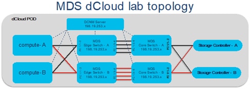
For more information on MINT engagements, please engage Cisco sales account team member. Cisco account team can open above URL and provide some of the details pertaining to the migration project and select which partner they would like to be part of.
dCloud
Save time with dCloud's curated content collections. With intelligent solution pairings and helpful insights, it's a whole new way to experience the Cisco portfolio. dCloud can bs used as a good resource to familiarize anyone with Cisco MDS switches, NX-OS and some of the key features like SAN Analytics. Cisco SAN switches have two different lab setups in the dCloud. One with regular MDS functionality like initial configuration, zoning/VSAN/Port Channel/interface configuration, and second one for SAN Analytics.
First demo of initial MDS config and other regular day to days task exercises are available via first demo located here: https://dcloud-cms.cisco.com/demo_news/cisco-mds-multilayer-director-switch-lab-v1. This lab showcases Cisco’s Storage Networking technology, consisting of Cisco MDS 9000 series switches. The solution demonstrates ease of deployment, configuration and maintenance. This solution also covers SAN Analytics feature – how to enable and start the Analytics.
Scenarios like Initial Configuration, Port Channel, Zoning, initial Analytics configuration, and NXAPI Functionalities are covered in this demo.
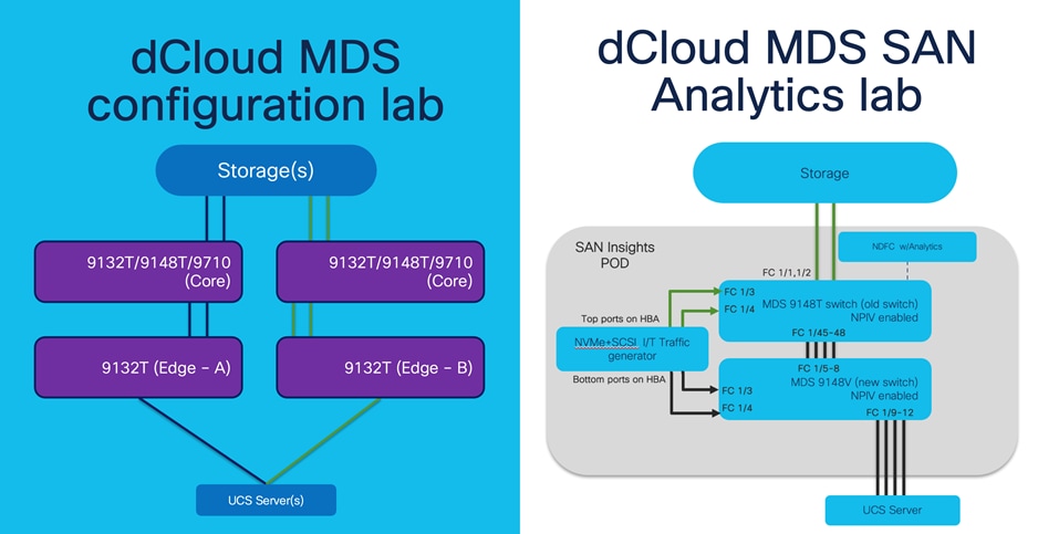
The second demo is about Cisco’s deep packet visibility, called SAN Insights (or SAN Analytics). This demo is in the read-only This demo provides the opportunity to see how Cisco SAN Analytics is integrated by design into the SAN between the compute and the storage layers. This is made possible by recent innovations in the 32G FC family of Cisco MDS 9000 switching family. We can look at multiple metrics at different level to find out busiest host or storage port, Exchange Completion Time (ECT), performance or bandwidth consumption, Number of IOPs, and much more by doing metric calculation for every flow. Components of this demo includes: Cisco Data Center Network Manager 11.4(1) release, Cisco MDS 9148T 32-Gbps Fibre Channel Switch, running NX-OS 8.4.(2b) release, Storage controller (Target), Servers (Initiators), Traffic Generator (Initiator / Target using SCSI / NVMe flows). This demo can be accessed from https://dcloud2.cisco.com/instantdemo/cisco-san-analytics-using-cisco-mds-9000-preview-v1.
Note that both the demos are physical lab devices so please be patient while you are accessing them. Initially it might take few more seconds to download the demo page.
Partner Blackbelt Training
Cisco Black Belt Academy provides a simplified & uniform role-based education framework across all Cisco architectures and solutions.
Black Belt Academy helps Cisco Partners and Distribution in Selling, Deploying and Supporting the latest technology and software solutions with enablement on tools and programs required for backend operations to better assist our joint customers. Cisco partners can select pre-sales or deployment or support tracks. There are three stages in each track and partners get additional incentives based upon their level of Blackbelt certification. The training content in Blackbelt academy is updated frequently to make sure partners are ready to sell and support using the latest technology and features. For more details, click here.
Cisco Learning Network
Cisco learning academy provides various levels of Cisco certifications, ranging from introduction to expert level. Cisco MDS 9000 series switches are part of CCNA, CCNP DC and CCIE level exams. Cisco learning network provides multiple level of different trainings to anyone who wants to learn more about Cisco MDS 9000 series SAN switches. Cisco learning network provides these trainings via in-person or virtual instructor based or self-learning (e-learning) modules. There is 1-day, 2-day and 5-day trainings anyone can attend for Cisco SAN solutions.
● Cisco MDS 9000 Series Switches Overview (DCMDSO) v1.5
● Configuring Cisco MDS 9000 Series Switches (DCMDS) v3.5
● Cisco Certified Technician Supporting Cisco Data Center System Devices (DCTECH) v3.0
● Managing SAN Infrastructure with Cisco Data Center Network Manager (DCNMS) v1.0
● Troubleshooting Cisco Data Center Infrastructure (DCIT) v7.0
Cisco MDS 9700 Series:
● Cisco MDS 9000 series Switches Quick Reference Guide
● Compare MDS 9700 series Multilayer Director Switches
Cisco MDS 9000 Family hardware installation guides:
● Hardware installation guides
● Cisco MDS 9700 Installation Guides
Important Cisco MDS 9000 Family guides:
● Interoperability matrix for Cisco Nexus and Cisco MDS 9000 Family products
● Cisco MDS 9000 Family Pluggable Transceivers Data Sheet
● Cisco Data Center Interoperability Support Matrix
● Cisco MDS 9000 NX-OS Software Release Notes
Blogs:
https://blogs.cisco.com/author/bhavinyadav
Cisco Storage Area Networking blog series:
● Spinning up an NVMe over Fibre Channel Strategy using Cisco MDS 9000 Series Multilayer Switches
● Cisco MDS 9000 series switches: Security is better when it is built in, not bolted on
● Cisco MDS 32G Fibre Channel Fabric switches: Small doesn’t mean less.
● Cisco MDS SAN Analytics: A GPS for Your SAN
● MDS 9000 Series Switch Architecture Part 1: Superior CRC Error Handling
Brocade Virtual Fabrics
The Brocade Virtual Fabrics feature augments the proven security and fault isolation features of Brocade Fabric OS, enabling organizations to create logical groups of separately managed devices, ports, and switches within a physical SAN. Virtual fabrics and fabric zoning have a complementary relationship. Physical ports or World Wide Names (WWNs) are assigned to virtual fabrics, and then zones are configured within the virtual fabric. Virtual fabrics may change, for example, when ports are needed or management boundaries change. When the Brocade Virtual Fabrics feature is activated, the capabilities of some features, such as administrative domains and port mirroring, are reduced. Brocade Virtual Fabrics are restrictive in their capabilities compared to Cisco VSANs, which offer greater flexibility and scalability. Virtual fabrics partition the physical infrastructure.
Brocade logical SAN (LSAN)
A Brocade LSAN consists of zones in two or more edge or backbone fabrics that contain the same devices. LSANs essentially provide selective device connectivity between fabrics without forcing you to merge those fabrics. Fibre Channel routers provide multiple mechanisms to manage inter-fabric device connectivity through extensions to existing switch management interfaces.
Cisco Virtual SAN (VSAN)
Cisco pioneered logical fabric separation with the introduction of VSANs in the first Cisco MDS 9000 Family products, introduced in 2002. A Cisco VSAN is a logical fabric in single or multiple switches built on a physical infrastructure to form a single fabric. Every VSAN has its own services, security, and other parameters, providing isolation of any problems within that VSAN boundary only, though the VSANs share the same physical switch and hardware. VSANs can also share frame tagging for shared ISLs. VSANs also support FICON. Multiple VSANs can be defined on a single switch. To separate the VSANs, you must assign each a unique domain ID. A single VSAN can span 239 physical switches, and you can create up to 256 VSANs in a single switch.
Multiprotocol SANs can use Fibre Channel with FCoE across Cisco Nexus switching platforms (Cisco Nexus 9000, 7000, and 5000 series switches) along with Cisco UCS Fabric Interconnects to span the platforms easily. Up to 256 VSANs can be configured in a switch. Of these, one is the default VSAN (VSAN 1), and another is an isolated VSAN (VSAN 4094). User-specified VSAN IDs range from 2 to 4093.
Brocade Virtual Fabrics and LSAN configurations can be migrated to Cisco VSAN configurations to provide greater scalability, performance, and interoperability. Cisco VSANs are supported across the entire Cisco MDS 9000 Family and Cisco Nexus 7000 and 5000 series switches.
For a single virtual fabric migration from Brocade, it is easy to migrate to the default Cisco VSAN (VSAN 1). The default VSAN requires only a simple port-to-port mapping between the two fabrics, though the use of VSAN 1 for production traffic is not a best practice. If the existing fabric has multiple Brocade Virtual Fabrics, you will have to create multiple Cisco VSANs to match the different virtual fabric groups.
Brocade Administrative Domains
An administrative domain is a logical grouping of fabric elements that define the switches, ports, and devices that you can view and modify. Administrative domains partition the administration of a fabric into logical groups and allocate these groups to different user accounts so that these accounts are restricted to manage only the administrative domains assigned to them. You can configure up to 256 administrative domains in a fabric (254 user-defined, 2 system-defined), numbered from 0 through 255. Each administrative domain is designated by a name and a number.
Inter-VSAN Routing and Virtual Fabric Routing
Cisco defines IVR to control and allow VSAN traffic within its boundaries and to set its own security and traffic policies. This approach enables easy management of the VSAN without disruption of other VSAN traffic. Devices in different VSANs communicate through a super-set zone called an IVR zone set. Only devices in the IVR zone set can see across VSAN boundaries. IVR offers an extension of the VSAN technology to provide cross-VSAN connectivity without the need to merge the routed virtual fabrics. This approach avoids propagation of irrelevant or potentially disruptive fabric events beyond the boundaries of a given VSAN. Using IVR, you can extend connectivity across VSAN boundaries and share a common storage resource among multiple VSANs, without the risk of destabilizing the fabric. IVR supports routing between all VSAN interoperate modes. IVR switches will modify the Fibre Channel headers for all communication between the end devices, including the VSAN number and source and destination FCIDs. Cisco IVR can be easily managed with less overhead. IVR is used mainly in situations in which problems arise with interoperability.
Device Aliases
Device aliases are the user-friendly names given to pWWNs. These aliases use one-to-one mappings to pWWNs and were developed to easily identify devices within the switch. They are used for purposes such as zoning and QoS. There are two types of device aliases: standard and enhanced. With standard aliases, the information is passed to the switch, which substitutes the WWN for the device alias and then passes it to the application or service being used. With enhanced mode, applications accept the device alias name in its native format, rather than expanding the alias to a pWWN. Because applications such as zone servers IVR and Dynamic Port VSAN Membership (DPVM) automatically track and enforce device alias membership changes, you have a single point of change.
Fibre Channel Aliases
Fibre Channel aliases are used to associate one or more pWWNs with a user-friendly name. They are also VSAN-specific; hence, if a device is moved from one VSAN to another, a new Fibre Channel alias is needed in the new VSAN. Fibre Channel aliases are propagated through zone-set activation (assuming that the zone-set distribution is set to the full zone set). Fibre Channel aliases are propagated as part of the full database only, if propagation of the full database is allowed in that specific mode.
The following table summarizes the differences between Fibre Channel aliases and device aliases.
Table 4. Fibre Channel alias and device alias comparison
| Fibre Channel alias |
Device alias |
| Used for zoning purposes only |
Multifunction (port security, IVR, zoning, etc.) |
| Can contain multiple pWWNs |
Can have only one pWWN |
| Configured per VSAN |
Not VSAN-specific |
| Used mainly in multivendor environments |
Used mainly if the fabric is Cisco MDS 9000 Family only |
The primary uses of device aliases and Fibre Channel aliases are summarized below:
● IVR zoning is easier to perform in Cisco DCNM when using device aliases.
● Fibre Channel aliases can use only zones and zone sets. Device alias can be used with any services that use Cisco Fabric Services.
● Fibre Channel aliases interoperate with some Brocade Fibre Channel switches.
● In Fibre Channel aliases, the full zone set is distributed, so they are available on all switches in the fabric.
● Device aliases are not VSAN-specific. After a device alias is created, it applies to that pWWN regardless of the VSAN, whereas with a Fibre Channel alias, a different alias needs to be defined for each VSAN.
● Device aliases are automatically distributed to other Cisco switches attached to the fabric.
● Troubleshooting is easier when using device aliases. After a device alias is assigned to a pWWN, any time that the pWWN is displayed, the device alias is also displayed. For example, CLI commands such as show flogi database and show fcns database will display the pWWN along with the associated device alias.
Persistent Fibre Channel IDs
Cisco MDS 9000 Family switches cache assigned FCIDs for each pWWN in volatile memory by default. In the event of any software or hardware failure, these assignments can be wiped out. The use of persistent FCIDs changes this behavior so that the assigned FCIDs and FCID-pWWN mappings are stored in nonvolatile memory. Some traditional operating systems such as HP-UX and AIX use the FCID of the SAN device mapped to the SCSI target number of the storage device to determine the logical unit number and OS storage mapping. Changing the FCID requires the server administrator to remap each LUN on each server. Persistent FCIDs can map the FCID of the storage device as the SCSI target number, so that these devices get the same FCID every time they perform a fabric login (FLOGI) to the switch. You may want to enable this feature less as a security precaution than as a way to achieve flexibility and availability in the event of migration. The FCID persistence feature is enabled by default on all Cisco MDS 9000 Family switches.
Domain IDs
The domain ID is part of the FCID. Every VSAN has its own unique domain ID on every interconnected switch. When the domain ID is changed, the switch itself will need to re-register with the principal switch in the fabric to verify the uniqueness of the domain ID. As a result, all devices attached to the switch will need to log into the switch again, which could be disruptive. Hence, use of a nonoverlapping static domain ID is preferred, to avoid any disruption from fabric events during migration.
Timers
Timers are extremely important for many purposes. For a Fibre Channel environment, timers can determine the time that packets are allowed to be considered in transit, and they can define various error-detection conditions, etc. The default values for these timers usually don’t need to be changed, but when merging fabrics from different vendors, you must be sure that they are set identically in both fabrics. All timers should be the same across all switches because these values are exchanged by E-ports when an ISL is established. They should be left at the default settings on all Brocade switches to make sure that the transition is smooth. All Cisco switches have the same timer settings unless they have been modified manually. Timers also are important parameters for interoperate mode migration. Some valuable timer parameters are the
Resource Allocation Time-Out Value (R_A_TOV), Error Detect Time-Out Value (E_D_TOV), Distributed Services Time-Out Value (D_S_TOV), Fabric Stability Time-Out Value (F_S_TOV), and Receiver Transmitter Time-Out Value (R_T_TOV).
Fabric Shortest Path First and Brocade Dynamic Load Sharing
Brocade Dynamic Load Sharing (DLS) is an exchange-based routing. Cisco uses Fabric Shortest Path First (FSPF) to dynamically compute routes through a fabric by establishing the shortest and quickest path between any two switches. It supports multipath routing based on the link-state protocol and domain ID. Cisco MDS 9000 Family switches use the default src-id, dst-id, and ox-id values (or src-id and dst-id values, if these are configured) to load balance across multiple ISLs, whereas Brocade switches use their default src-id and dst-id values.
Inter-Switch Link and Inter-Chassis Link
Cisco ISLs can be configured between any Cisco MDS 9000 Family switches and line cards. Brocade ICLs use the same algorithm as Cisco Extended ISLs (EISLs), but the links can be used only between like-generation Brocade DCX switches and not with any other models or brands. The Brocade ICLs also need to go through the same Application-Specific Integrated Circuit (ASIC) in the backend of Brocade CR-module, which means that the ports used by ICLs must come from the same ASIC in the back end.
PortChannel and Trunking
A PortChannel is an aggregation of FC/FCoE/FCIP links into a single logical link to provide a fault-tolerant, high bandwidth single link. A PortChannel can include all Fibre Channel, Fibre Channel over Ethernet (FCoE), or Fibre Channel over IP (FCIP) ports between two chassis. Brocade uses the term “trunking,” and Cisco uses the term “PortChannel” to describe the aggregation of multiple ISLs into a single logical ISL.
Cisco PortChannel technology is supported between different line cards, different ASICs, and different port groups. Cisco MDS 9000 Family switches support a maximum of 16 ISLs per PortChannel and 16 parallel Port Channels between chassis, depending upon the switch model. Brocade supports a maximum of 8 ISLs from the same ASIC on the module, which can be combined into a single logical ISL.
Trunking and Port Channels are not supported between switches from two different vendors. However, some vendors can continue to use trunking and Port Channels between their own switches while in interoperability mode. This feature can be disabled on a per-port or per-switch basis and can continue to work as expected only if it is allowed by the interoperability mode of the vendor.
VSAN Trunking
VSAN trunking is the trunking of multiple VSANs using a single ISL or group of ISLs and becomes an EISL using VSAN header information. This feature enables a common group of ISLs to be used as a pool for connectivity between switches for multiple fabrics. It uses industry-standard Virtual Fabric Tagging (VFT) extended headers to provide traffic segregation across common trunked ISLs. The primary benefit of VSAN trunking is that it consolidates and reduces the number of distinct ISLs required between switches. For organizations that have multiple fabrics between data centers, VSAN trunking enables a common pool of ISLs to be used, reducing the number of individual ISLs. This approach typically results in substantial cost savings through reduction in the number of Dense Wavelength-Division Multiplexing (DWDM) transponders or dark fiber pairs, allowing separate logical VSAN fabrics between sites through VSAN pruning. All VSANs do not need to go through a trunked ISL. Furthermore, individual fabrics often have very different load profiles, and grouping them together can result in higher overall throughput. VSAN trunking also allows a more controlled environment in which priority can be given to specific traffic or devices, and QoS policy can be applied to provide guaranteed bandwidth allocation for specific devices or VSANs.
Zoning
Zones help you define security and provide control over communications between multiple storage devices and user groups. Zones can be created by the administrator to increase security to help prevent data loss through corruption or spoofing. Zoning is enforced by looking at the source and destination ID fields. A zone consists of multiple zone members that can access each other. A device can belong to multiple zones, and zone size can vary. By default, all members are in the default zone unless they are part of some other active zone. Zones can be part of multiple zone sets. The default zone policy for the Cisco MDS 9000 Family switch zone set denies communication between devices. The default zone behavior of permit or deny (all nodes are isolated when not explicitly placed in a zone) may change. The default zone parameter is restricted to the switch on which it is configured, and it is not propagated to other switches. Deny is the recommended setting to help secure the environment. While configuring zones, a zone with a single initiator and a single target provides the most efficient use of switch resources.
Zone Set
A zone set comprises one or more individual zones. A single zone can be part of multiple zone sets. There are two types of zones: active and local. Active zone sets define the zone rules to enforce zoning security. This type of zone set cannot be modified and is distributed to all switches in the VSAN. There can be only one active zone set. A local zone set contains the complete the zone-set database for that switch. This zone set can then be activated to become the active zone set. A VSAN can have multiple local zone sets.
Zone Membership
Zoning can be enforced in two ways: through hard zoning and soft zoning. Hard zoning is enforced with the hardware of each switch for each frame. As soon as a frame reaches the switch, the source and destination IDs are compared with ACL combinations to allow or deny the frame. Hard zoning can be applied to all forms of zoning. Hard zoning is also more secure than soft zoning because it is applied to every frame to help prevent unauthorized access.
Soft zoning is applied only for the duration of interaction between the name server and the end device. If an end device knows the FCID of a device outside its zone, it can access it easily.
A switch can be preconfigured with a set of zones, with zone membership based on the port to which a device is connected (hard zoning). If other proprietary zoning methods (physical port numbers) are eliminated, zones may be limited to the pWWN. Not all vendors can support the same number of zones. Determine the lowest common denominator with Brocade and limit the fabric to the values in the following table.
Table 5. Zone types in interoperability mode
| Zone type |
Cisco MDS 9000 Family–compatible interoperability modes |
| pWWN |
All |
| FCID |
Non-interoperability mode only |
| Fabric pWWN |
Non-interoperability mode only |
| Fibre Channel alias |
All |
| Domain and port |
Traditional switch interoperability modes 2, 3, and 4 |
| Symbolic node name |
Non-interoperability mode only |
| Interface and switch WWN |
Non-interoperability mode only |
Zone-set Database and Propagation
A zone-set database and an active zone set are two separate entities. A zone-set database is a local database on each switch that contains all the zone sets, zones, and zone member information, whereas each VSAN in the fabric has a single active zone-set entity derived from the zone-set database of the local switch. This active zone set is distributed to all the switches in the fabric upon activation and remains consistent across all the switches in the fabric, whereas the zone-set database is a local entity and does not need to be homogeneous in the fabric. The zone-set database is not identical on all the switches, which could lead to problems. Multiple switches can be used to configure zoning information at different times, but upon activation only the local switch zone-set database is enforced by the fabric.
This behavior could be disruptive if proper attention is not paid to the zoning methodology, and for that reason some switch vendors recommend use of a seed switch for all zoning configurations. Use of a seed switch can definitely alleviate this problem; however, Cisco MDS 9000 Family switches also provide two commands:
● The EXEC level zoneset distribute command distributes the zone-set database of that switch to the entire fabric upon activation.
● The config level zoneset distribute command distributes the zone-set database of that switch upon zone-set activation.
Use of the config level zoneset distribute command on all switches in the fabric is highly recommended. After this command is activated, all the switches in the fabric will have a consistent zone-set database in the active zone-set entity. Using the Enhanced Zoning feature, the administrator performs all configurations within a single configuration session on switch in the fabric. When you begin a session and start zoning configuration, the switch locks the entire fabric for entire VSAN, to avoid any conflicting changes by multiple users.
Note: The Cisco DCNM for SAN GUI tool always uses the principal switch as the seed switch for all zoning configurations.
Brocade FOS and Cisco NX-OS CLI command mappings
Here is the mapping of few important and frequently used CLI commands between Brocade Fabric OS (FOS) and Cisco NX-OS.
Key difference between Brocade FOS and Cisco NX-OS - Command Availability
Brocade Fabric OS (FOS) provides a flat command line interface (CLI). All types of commands (display or configuration) are executed on the same prompt. For example, portshow command displays details of a port and portdisable command disables a port.
Cisco NX-OS provides multiple mode command line interface (CLI). The default login prompt is called exec mode. All the display commands are available in exec mode. Display commands start with the keyword ‘show’ followed by the feature/component. For example, interface details are displayed by command ‘show interface’. Configuration is edited by entering config mode using command ‘configure terminal’.
Cisco NX-OS is also less vulnerable to security issues due to separation of Linux OS and NX-OS. Cisco NX-OS also provides single command set for multiple VSANs compared to multiple different partitions for each Fabric-ID in Brocade.
Here are few frequently used commands, side-by-side:
| Brocade |
Cisco MDS |
| portCfgShow |
show interface |
| portCfgSpeed [slotnumber/]portnumber, mode |
config t |
| portDisable [slotnumber/]portnumber |
config t |
| portErrShow portStatsShow |
show interface |
| portPerfShow |
show interface counters brief |
| portShow |
show interface brief |
| portStatsClear |
clear counters interface fcXX/XX |
| trunkShow trunkDebug |
show interface trunk vsan XX |
| zoneAdd zoneName, member;member |
zoneset <zoneset_name> vsan XX |
| zoneCreate zonename, member; member |
config t |
| zoneDelete zonename |
Config t |
| zoneRemove zonename, zoneMemberList |
config t |
| zoneShow |
show zoneset |
| cfgCreate |
config t zoneset <zoneset_name> vsan XX |
| cfgDelete |
clear zone database vsan XX |
| cfgRemove |
config t |
| cfgDisable |
no zoneset activate <zoneset_name> vsan XX |
| cfgEnable |
zoneset activate <zoneset_name> vsan XX |
| cfgSave |
copy running-config startup-config |
| cfgActvShow |
show zone status |
| Fabric switch - portenable <portnumber> Director – portenable <slot_no> port<port_no> |
interface <fcx/y> no shut |
| Fabric switch portdisable <portnumber> Director – portdisable<slot_no> port<port_no> |
interface <fcx/y> shut |
| portCfgSpeed portnumber <speed> |
interface fc<x/y> switchport speed <speed> |
| portname portnumber -n “desired name” |
interface fc<x/y> switchport description <name> |
| Troubleshooting commands |
|
| supportshow supportsave |
show tech-support show tech-support brief show tech-support details |
| errDump |
show logging |
| errClear |
clear logging logfile |
| errShow |
attach module XX |
| chassisName |
show switchname |
| chassisShow |
show hardware |
| configDefault |
write erase |
| configShow |
show running-config show startup-config |
| configUpload |
copy nvram:startup-config tftp://<ip-addr>/my-config |
| configDownload |
copy tftp://ip-addr/my-config nvram:startup-config |
| date |
show clock |
| fabricShow |
show fcdomain domain-list vsan XX |
| Reboot |
reload |
| Uptime |
show system uptime |
| Date |
show clock |
| Version |
show clock |
| portshow < port_no> |
show interface fc<x/y> |
Hardware comparison chart: List of equivalent hardware platforms in Cisco and Brocade environments.
| Cisco MDS SAN Switches |
Equivalent Brocade FC SAN portfolio |
| MDS 9132T (32x 32G ports) |
G610 (24x32G ports) |
| MDS 9148T (48x 32G ports) |
G620 (48x 32G ports) |
| MDS 9396T (96x 32G ports) |
G630 (96x 32G ports) |
| MDS 9220i (12x 32G FC + [4x1/10GE + 2x25GE + 1x40GE] FCIP ports) |
7810 (12x 32G FC + 6x1/10GE FCIP) |
| MDS 9250i (40x 16G FC + 8x10GE FCoE + 2x 10GE FCIP) |
7840 (24x16G FC + [16x 1/10GE + 2x 40GE] FCIP ports) |
| MDS 9706 |
X6-4 |
| MDS 9710 |
X6-8 |
| MDS 9706 |
X7-4 |
| MDS 9710 |
X7-8 |
| MDS 9718 |
None |