Cisco Hybrid Multi-Cloud Networking Design Guide
Available Languages
Bias-Free Language
The documentation set for this product strives to use bias-free language. For the purposes of this documentation set, bias-free is defined as language that does not imply discrimination based on age, disability, gender, racial identity, ethnic identity, sexual orientation, socioeconomic status, and intersectionality. Exceptions may be present in the documentation due to language that is hardcoded in the user interfaces of the product software, language used based on RFP documentation, or language that is used by a referenced third-party product. Learn more about how Cisco is using Inclusive Language.
- US/Canada 800-553-2447
- Worldwide Support Phone Numbers
- All Tools
 Feedback
 Feedback
This document describes the design options and the deployment considerations for Cisco Multi-Cloud Networking with AWS and Microsoft Azure. The following use cases are considered:
· Application stretched across sites (intra-tenant)
· Shared Services in Hybrid Multi-Cloud Environment
· Cloud to Internet using cloud native routing functionality
· Cloud to External networks through on-premises L3 Outsides (L3Outs)
· Connect to External Site using Cloud Native Routing Service
· External connectivity to WAN, Branch or Non-ACI site
· Inter-working with SD-WAN solutions
· Multi-Node services insertion
· Cloud Native Service Integration on Microsoft Azure
· Brownfield Import on Microsoft Azure and AWS
· Workload Mobility for Disaster Recovery (DR)
· Firewall redundancy with AWS GWLB (Gateway Load Balancer)
This document assumes that the reader has a fundamental knowledge of Cisco ACI and Multi-Cloud Networking technology.
Cisco ACI and Multi-Cloud Networking offers the capability to manage policies and network connectivity across multiple on-premises Cisco ACI data centers as well as public cloud platforms. For more information, refer to Cisco Cloud ACI on AWS White Paper and Cisco Cloud ACI on Microsoft Azure White Paper.
Cisco ACI service graph offers the capability to insert Layer 4 to Layer 7 services, such as firewalls, load balancers, and Intrusion Prevention Systems (IPS). For more information, refer to Cisco ACI service-graph-design white paper.
This document uses the following terms that you must be familiar with:
· Cisco ACI and Cisco Multi-Cloud Networking terms:
o Cisco Cloud Network Controller (formerly called Cisco Cloud Application Policy Infrastructure Controller: Cisco Cloud APIC) *
o Nexus Dashboard Orchestrator (NDO)
o Virtual Routing and Forwarding (VRF)
o Bridge Domain (BD)
o Endpoint Group (EPG)
o Layer 3 Out or external routed network (L3Out)
o Subnet-based EPG in Layer 3 Out (L3Out External EPG)
o Service Graph
· AWS terms:
o Virtual Private Cloud (VPC)
o Security Group (SG)
o Application Load Balancer (ALB)
o Network Load Balancer (NLB)
· Azure terms:
o Virtual Network (VNet)
o Network Security Group (NSG)
o Application Security Group (ASG)
o Azure Application Gateway
o Basic Load Balancer
o Standard Load Balancer
o Microsoft Enterprise edge router (MSEE)
* Prior to Cisco Cloud Network Controller Release 25.0(5), it was called Cisco Cloud Application Policy Infrastructure Controller (Cloud APIC). This document still uses “Cloud APIC” and Cloud APIC icons in the sections written prior to Release 25.0(5) or in the sentences that indicate the Release prior to 25.0(5).
The main goal of this document is to provide design guidelines for Cisco Multi-Cloud Networking use cases. ACI Multi-Cloud is the solution used to interconnect multiple cloud environments such as on-premises Cisco ACI, site, Amazon Public Cloud (AWS) and Microsoft Azure (Azure).
The following figure illustrates a brief topology example of Cisco Multi-Cloud Networking connecting an on-premises ACI fabric, an AWS environment, and a Microsoft Azure environment.
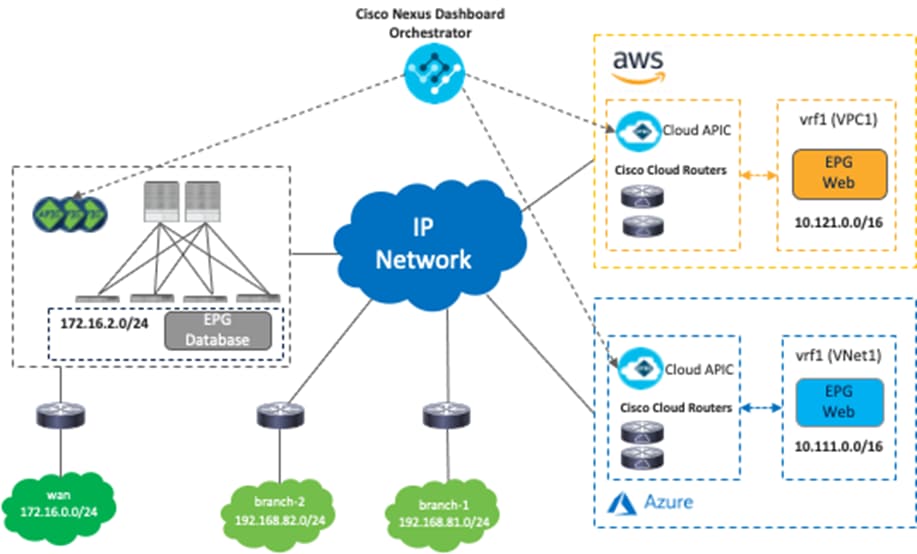
As illustrated in Figure 1, Cisco Multi-Cloud Networking consists of the following components:
· Cisco Nexus Dashboard Orchestrator (NDO): NDO acts as a central policy controller, managing policies across multiple on-premises Cisco ACI data centers as well as public cloud platforms, with each cloud site being abstracted by its own Cisco Cloud Network Controller. NDO runs as a service on top of Nexus Dashboard, where Nexus Dashboard can be deployed as a cluster of physical appliances or virtual machines running on VMware ESXi, Linux KVM, Amazon Web Services or Microsoft Azure. Inter-version support was introduced previously, so NDO can manage on-premises APICs and Cisco Cloud Network Controllers running different software versions.
· Cisco Cloud Network Controller (formerly Cisco Cloud APIC): Cisco Cloud Network Controller runs as a virtual instance on a supported public cloud to provide automated connectivity, policy translation, and enhanced visibility of workloads in the public cloud. The Cisco Cloud Network Controller translates all the policies received from NDO and programs them into cloud-native constructs, such as VPCs and security groups on AWS, and VNets, application security groups and network security groups on Microsoft Azure. Cisco Cloud Network Controller is deployed through the public cloud Marketplace, such as AWS Marketplace and Azure Marketplace.
· Cisco Cloud Router (CCR): The Cisco Cloud Router is an important component in the public cloud platforms. CCRs are used for inter-site communication to on-premises sites and the public cloud platforms. In addition, CCRs are also used for inter-VNet communication within Microsoft Azure. Though this document uses the term CCR, it is important to note that prior to Cisco Cloud APIC Release 25.0(3), Cisco Services Router 1000V (CSR1000V or CSR) is used as the CCR, and starting from Cisco Cloud APIC Release 25.0(3), Cisco Catalyst 8000V (C8000V) is used as the CCR for new deployments by default. The C8000V is a new Cloud Virtual Router platform that provides better performance. For the existing deployment prior to Release 25.0(3) with CSRs, once Cloud APIC is upgraded to Release 25.0(3) or later, you are required to migrate from the older CSR1000Vs to the newer C8000Vs. During the migration, the CSRs are brought down one at at a time, which reduces the capacity, but traffic disruption should be minimal. Starting from Release 25.0(3), the Cloud APIC user interface refers to the C8000V as CCR (Cisco Cloud Router).
· On-Premises ACI fabric (optional): On-premises ACI fabric is managed by Cisco APIC. Although Cisco Multi-Cloud Networking doesn’t mandate the existence of an on-premises ACI fabric, it’s common to have both on-premises data centers and public cloud platforms.
This section briefly covers the network and security models on Cisco ACI, AWS, and Microsoft Azure, since each cloud provider has slightly different constructs and terminologies. For example, a VRF on an on-premises ACI fabric can be interpreted as a VPC on AWS and as a VNet on Microsoft Azure, even though they are not identical (a VPC/VNet can have multiple routing tables whereas a VRF can have one routing table). In addition, a VRF on an on-premises ACI fabric can be interpreted as multiple VPCs (VPC1 in Region-1 and VPC2 in Region-2) on AWS and VNets (VNet1 in Region-1 and VNet2 in Region-2) on Microsoft Azure.
Following are other examples:
· Cisco ACI network policy model uses tenants, Bridge Domains (BDs), bridge-domain subnets, Endpoint Groups (EPGs), and contracts.
· AWS uses user accounts, Virtual Private Cloud (VPC), security groups, security group rules, and network access-lists.
· Microsoft Azure uses Resource Groups, Virtual Network (VNet), Application Security Groups (ASG), Network Security Groups (NSGs), outbound rules, and inbound rules.
The following figures illustrate the network and security models of Cisco ACI, AWS, and Microsoft Azure.
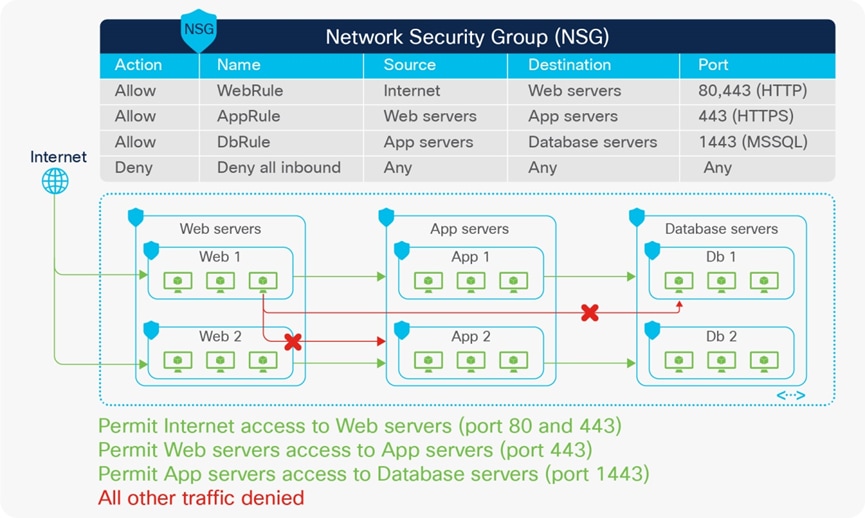
To have a consistent policy model for ease of operation and security, a mapping model is needed to help maintain the same perspective between different objects in an on-premises ACI site and public cloud platforms. For instance, an administrator can define a policy rule to allow web servers to communicate to database servers on a particular port. The policy rule is then applied to all endpoints regardless of their location.
Nexus Dashboard Orchestrator creates the model, and the objects and policies are rendered to concrete objects on the physical fabrics and cloud infrastructures by the APIC controllers in the on-premises ACI site and the Cisco Cloud Network Controller on AWS or Azure.
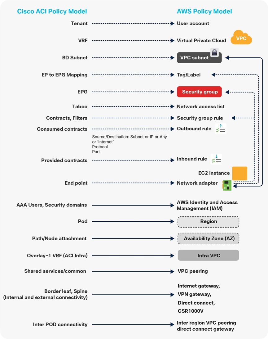
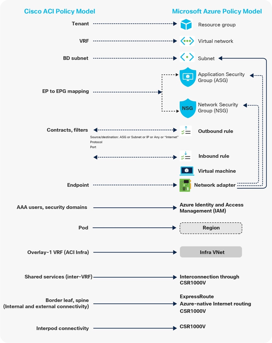
Figures 6 and 7 highlight the mapping between objects in the Cisco ACI policy model and the cloud native constructs available on AWS and Microsoft Azure. For example:
· An ACI contract is mapped to Security Group (SG) rules on AWS and Network Security Group (NSG) rules on Microsoft Azure.
· Contract rules are mapped to SG rules on AWS and NSG rules on Microsoft Azure.
Where security rules are enforced depends on the Cloud environment. In the case of AWS, SG rules are applied directly to network interfaces of AWS instances (cloud endpoints). In the case of Microsoft Azure, from Release 5.1(2), NSG rules are applied to subnets on Azure where the virtual machine resides. Virtual machines are grouped into an Application Security Group (ASG), which refers to the source or destination of the NSG. All those mappings are dynamically rendered by Cloud Network Controller, which is one of the essential components of the Multi-Cloud Networking solution.
For more information, please refer to the following white papers:
Multi-Region Hybrid Cloud Platforms Design
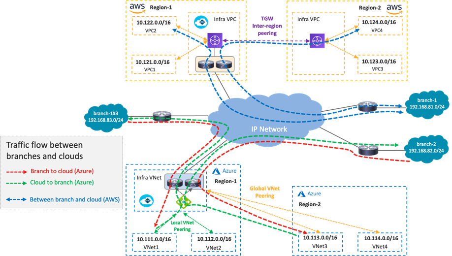
This section explains traffic flow in multi-region hybrid cloud platforms topology.
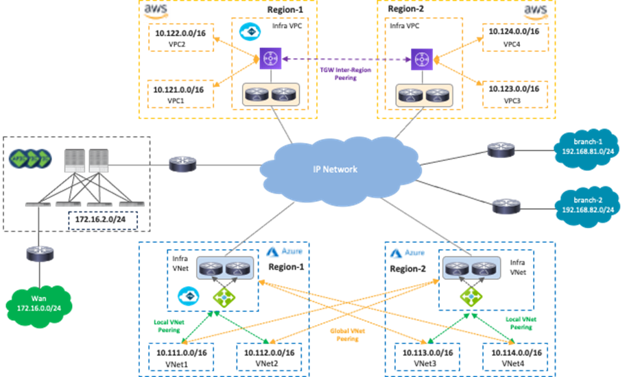
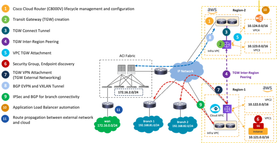
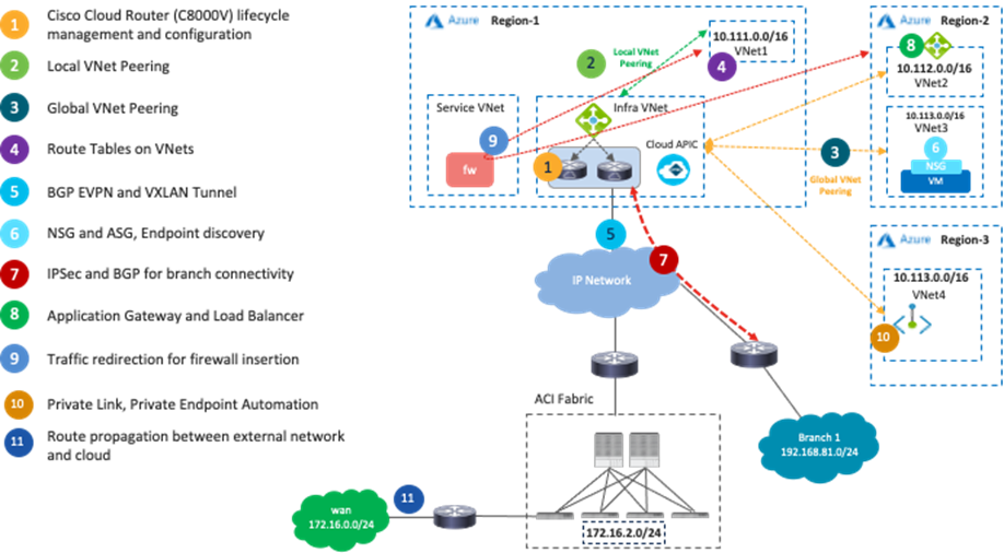
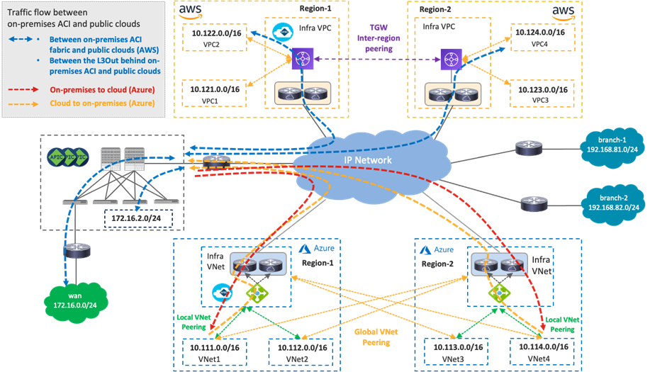
The following figure illustrates a topology example used in this section. It consists of the following networks:
· On-premises Cisco ACI fabric:
o Bridge domain subnet (172.16.2.0/24 is a bridge domain subnet)
o External network (172.16.0.0/24 is an external destination that is reachable via an on-premises L3Out)
· Cloud sites:
o Microsoft Azure: Region 1 and 2 (10.111.0.0/16, 10.112.0.0/16, 10.113.0.0/16 and 10.114.0.0/16 are VNet CIDRs)
o AWS: Region-1 and Region-2 (10.121.0.0/16, 10.122.0.0/16, 10.123.0.0/16 and 10.124.0.0/16 are VPC CIDRs)
· Branch networks:
o branch-1 (192.168.81.0/24 is the first branch network)
o branch-2 (192.168.82.0/24 is the second branch network)
NDO and Cisco Cloud Network Controller orchestrate various network-related configurations across cloud platforms in different regions to allow traffic flows over multi-region hybrid cloud environments. Examples of network-related configurations include:
· AWS: VPCs, CIDRs, subnets, route tables, TGWs, TGW peerings, Security Groups, Security Group rules, and Application Load Balancers.
· Microsoft Azure: VNets, CIDRs, subnets, route tables, VNet peerings, Network Security Groups, Application Security Groups, Azure Application Gateway, and Network Load Balancer.
· Cisco Cloud Router life cycle management and configuration.
The following figures illustrate what is automated by NDO and Cisco Cloud Network Controller.
One of the main advantages of deploying Cisco Multi-Cloud Networking solution is network connectivity orchestration and operational simplicity with multiple cloud environments.
The following table summarizes the traffic flows explained in this section, and the following sub-sections explain each scenario in greater detail.
Table 1. Traffic Flow Patterns
| Traffic pattern |
Traffic flow |
| Traffic Flow Within Public Cloud Platforms (Private subnet to private subnet) |
Traffic is forwarded via cloud native routing functionalities such as AWS TGW or Microsoft Azure VNet peering. |
| Traffic Flow Between Public Cloud Platforms (Private subnet to private subnet) |
Traffic is forwarded over the VXLAN tunnel between Cisco Cloud Routers in the cloud platforms. |
| Traffic Flow Between an On-Premises ACI Fabric and Public Cloud Platforms (Private subnet to private subnet) |
Traffic is forwarded over the VXLAN tunnel between Cisco Cloud Routers in the cloud platforms and the Cisco ACI spine switches. |
| Traffic Flow Between the Internet and Cloud Platforms (Public subnet to private subnet) |
Traffic is forwarded via cloud native routing functionality such as AWS IGW (Internet Gateway) and Microsoft Azure default system route. |
| Traffic Flow Between External Networks and Cloud Platforms (Private subnet to private subnet) |
Traffic is forwarded over the IPsec tunnel between Cisco Cloud Routers in the cloud platforms and the branch routers. |
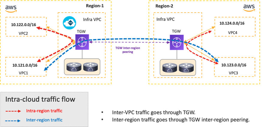
Intra-Region and Inter-Region Traffic Flow Within Public Cloud Platforms
The following figures illustrate the traffic flow established between two regions of the same public cloud provider.
In the case of Cisco Multi-Cloud Networking with AWS, inter-VPC traffic within the same region is forwarded via the local Transit Gateway (TGW). Inter-region traffic is forwarded across the cloud provider private backbone leveraging the peering between TGWs across regions.
Cisco Cloud Network Controller takes care of TGW creation, TGW attachment configuration for each VPC, TGW inter-region peering, VPC route table creation, VPC route table configuration for each VPC.
In the case of Cisco Multi-Cloud Networking with Microsoft Azure, inter-VNet traffic is forwarded to the Azure Load Balancer in the infra VNet via VNet peering, and traffic is load balanced to one of the Cisco Cloud Routers in the infra VNet. Then, the Cisco Cloud Router forwards the traffic to the destination VNet via VNet peering. The return traffic could go to a different Cisco Cloud Router based on the load balancing.
Cisco Cloud Network Controller takes care of the configurations for the VNet peering, Azure Load Balancer, Cisco Cloud Router, and route table for each VNet.

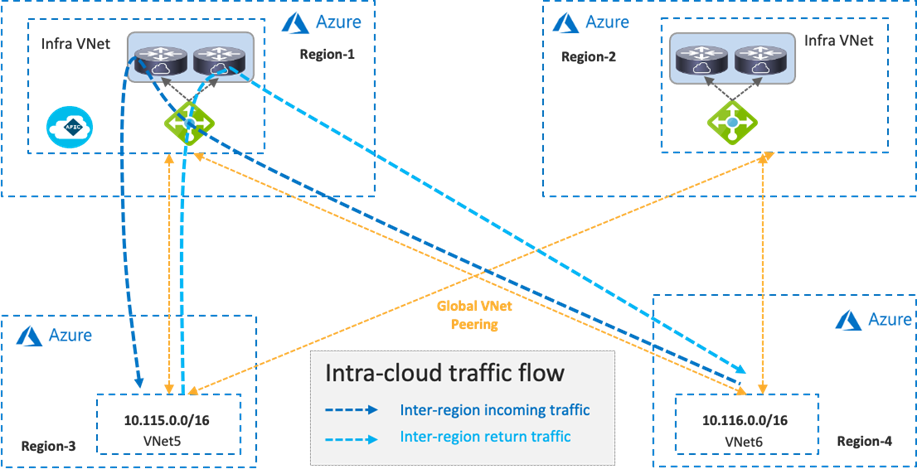
Inter-region traffic is forwarded to different Azure Load Balancers for incoming and return traffic because traffic destined to private subnets outside of the local VNet is forwarded to the local Azure Load Balancer in the same region. After load balancing to a Cisco Cloud Router, traffic is forwarded to the destination VNet via Global VNet peering.
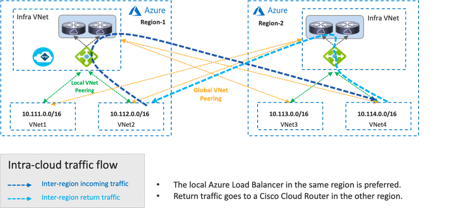
If there is no local Azure Load Balancer in the same region, traffic is forwarded to the Azure Load Balancer in the destination region via Global VNet peering.
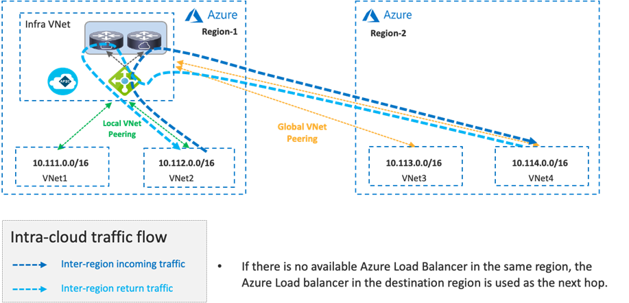
If there are multiple Azure Load Balancers available in different regions, Cisco Cloud Network Controller decides which Azure Load Balancer to use as the next hop by updating the route tables for the VNets. This decision is based on multiple factors, such as the Cisco Cloud Router configuration and availability. Though the example in the following figure uses the same Azure Load Balancer for both directions, traffic could be forwarded to different Azure Load Balancers for incoming and return traffic.
For tenant designs and guidelines, please refer to the following sections:
· Use case #1: Application stretched across sites (intra-tenant)
· Use case #2: Application stretched across sites (inter-tenant shared service)
Traffic Flow Between Public Cloud Platforms
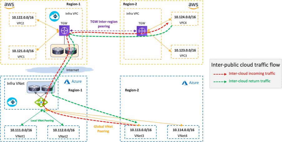
The following figure illustrates a traffic flow between private subnets in different public cloud platforms.
Traffic destined to private subnets outside of the public cloud is forwarded to the local TGW or the local Azure Load Balancer. Then, traffic is forwarded to a Cisco Cloud Router in the same cloud and goes to a Cisco Cloud Router in the other side over the VXLAN tunnel based on the routing table on the Cisco Cloud Router.
· If the destination IP subnet is in the on-premises ACI fabric, the Cisco Cloud Router sends the traffic to the router in the on-premises ACI. Please see Traffic flow between an on-premises ACI fabric and public cloud platforms.
· If the destination IP subnet is in another external network such as branch networks, the Cisco Cloud Router sends the traffic to the router in the destination location. Please see Traffic flow between external networks and cloud platforms.
Although the example in the following figure uses the same Cisco Cloud Routers for both directions, traffic could go through different Cisco Cloud Routers for incoming and return traffic. Traffic from another cloud to Microsoft Azure doesn’t go through the Azure Load Balancer as illustrated in the following figure.
In addition to the public cloud network configurations such as route tables, TGW, VNet peering and Azure Load Balancer, Cisco Cloud Network Controller takes care of the Cisco Cloud Router configurations, including the VXLAN tunnel.
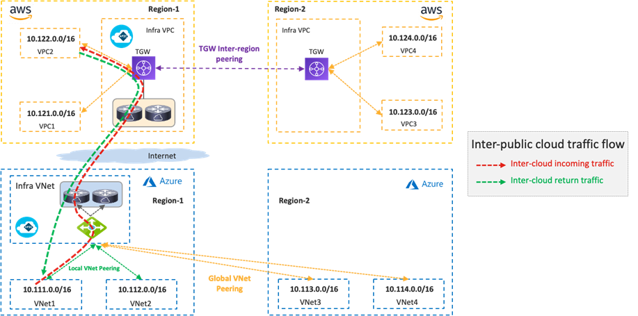
If there is no Cisco Cloud Router in the same region, traffic is forwarded to a region where a Cisco Cloud Router resides and then forwarded to the destination public cloud via VXLAN between Cisco Cloud Routers.
For tenant designs and guidelines, please refer to the following sections:
· Use case #1: Application stretched across sites (intra-tenant)
· Use case #2: Application stretched across sites (inter-tenant shared service)
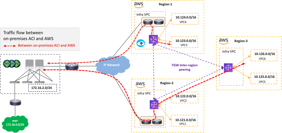
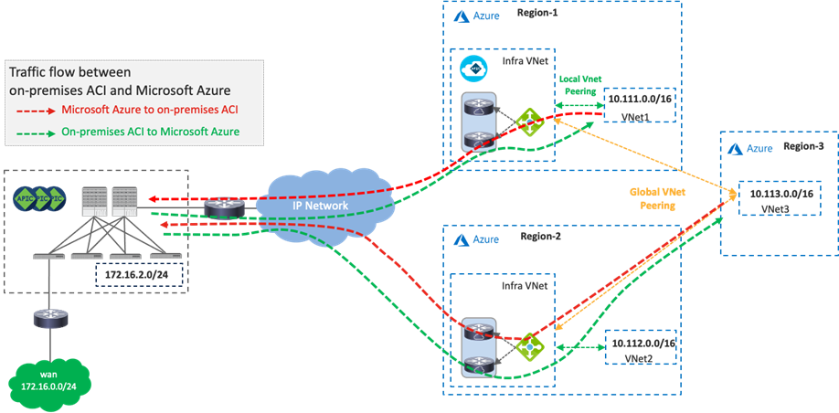
Traffic Flow Between an On-Premises ACI Fabric and Public Cloud Platforms
The following figure illustrates a traffic flow between an on-premises ACI fabric and public cloud platforms.
Traffic destined to private subnets outside of the source VPC or VNet is forwarded to the local TGW or the local Azure Load Balancer. Then, traffic is forwarded to a Cisco Cloud Router in the same cloud and goes to a router in the on-premises ACI fabric over the VXLAN tunnel, based on the routing table on the Cisco Cloud Router.
· If the destination IP subnet is in another public cloud, the Cisco Cloud Router sends the traffic to a Cisco Cloud Router in the destination public cloud. Please see Traffic flow between public cloud platforms.
· If the destination IP subnet is in another external network such as branch networks, the Cisco Cloud Router sends the traffic to the router in the destination location. Please see Traffic flow between external networks and cloud platforms.
After traffic arrives on the on-premises ACI fabric, depending on the destination IP subnet, it’s forwarded to the destination endpoint in the on-premises ACI fabric or the external network via the L3Out. NDO and the on-premises APIC take care of the network deployment in the on-premises ACI fabric.
Although the examples in the following figures use the same Cisco Cloud Routers for both directions, traffic could go through different Cisco Cloud Routers for incoming and return traffic. Traffic from an on-premises ACI fabric to Microsoft Azure doesn’t go through the Azure Load Balancer, as illustrated in the following figure.
In addition to the public cloud network configurations, such as route tables, TGW, VNet peering, and Azure Load Balancer, Cisco Cloud Network Controller takes care of the Cisco Cloud Router configurations, including the VXLAN tunnel. NDO generates configuration templates for the router in on-premises ACI fabric. Because the configuration templates are based on Cisco IOS-XE CLI syntax, cloud administrators might need to edit it to match their router.
If there is no Cisco Cloud Router in the same region, traffic is first forwarded to a region where a Cisco Cloud Router resides, and is then forwarded to the destination via VXLAN between the Cisco Cloud Router and a spine switch in the on-premises ACI fabric. Although traffic between an endpoint in Region-3 and the on-premises ACI fabric in the following figures use the Region-2 Cisco Cloud Router for both directions, traffic could go through different Cisco Cloud Routers in different Regions for incoming and return traffic.
For tenant designs and guidelines, please refer to the following sections:
· Use case #1: Application stretched across sites (intra-tenant)
· Use case #2: Shared Service in hybrid multi-cloud environment
· Use case #3: Cloud to External networks through on-premises L3 Outsides (L3Outs)
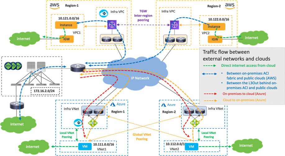
Traffic Flow Between the Internet and Cloud Platforms
The following figure illustrates a traffic flow between the internet and cloud platforms.
As illustrated by the green arrows, traffic destined to the Internet is forwarded via cloud native routing functionality, such as AWS Internet Gateway (IGW) or Microsoft Azure default system route, which doesn’t go through the TGW, VNet peering or Cisco Cloud Routers. Cisco Cloud Network Controller adds the default route to the AWS route table, which points to the Internet Gateway as the next hop.
Another example is the use of an L3Out in an on-premises ACI fabric. In this case, which is similar to the Traffic flow between an on-premises ACI fabric and public cloud platforms scenario, traffic destined to the Internet is forwarded to the on-premises ACI fabric and is forwarded to the external network via the L3Out. NDO, Cisco Cloud Network Controller, and the on-premises APIC take care of the network deployment across the on-premises ACI fabric and public cloud platforms.
Although the example in the following figure uses the same Cisco Cloud Routers for both directions, traffic could go through different Cisco Cloud Routers for incoming and return traffic. Traffic from an on-premises ACI fabric to Microsoft Azure doesn’t go through the Azure Load Balancer.
For tenant designs and guidelines, please refer to the following sections:
· Use case #3-1: Cloud to Internet using cloud native routing functionality
· Use case #3-2: Cloud to External networks through on-premises L3 Outsides (L3Outs)
Traffic Flow Between External Networks and Cloud Platforms
The following figure illustrates a traffic flow between external networks and cloud platforms. In this example, the branch networks are used as the representation of external networks.
In this case, which is similar to the Traffic flow between an on-premises ACI fabric and public cloud platforms scenario, traffic destined to the private subnets outside of the source VPC/VNet is forwarded to the local TGW or the local Azure Load Balancer. Then, traffic is forwarded to the Cisco Cloud Router in the same cloud and goes to the router in the destination location (branch networks in this example) over the IPsec tunnel based on the routing table on the Cisco Cloud Router.
· If the destination IP subnet is in another public cloud, the Cisco Cloud Router sends the traffic to a Cisco Cloud Router in the other public cloud. Please see Traffic flow between public cloud platforms.
· If the destination IP subnet is in the on-premises ACI fabric, the Cisco Cloud Router sends the traffic to the router in the on-premises ACI. Please see Traffic flow between an on-premises ACI fabric and public cloud platforms.
Although the example in the following figure uses the same Cisco Cloud Routers for both directions, traffic could go through different Cisco Cloud Routers for incoming and return traffic. In the case of Microsoft Azure, traffic from an external network to Microsoft Azure doesn’t go through the Azure Load Balancer, as illustrated in the following figure.
For tenant designs and guidelines, please refer to the following sections:
· Use case #4: Connect to External Site using cloud native routing service
· Use case #5: External connectivity to WAN, Branch or Non-ACI site
· Use case #6: Inter-working with SD-WAN solutions
This sub-section describes the intersite connectivity between on-premises ACI sites and cloud sites.
The on-premises ACI sites and the cloud sites are connected through IPsec tunnels with OSPF as the dynamic routing protocol for the underlay network reachability between the Cisco Cloud Router and the on-premises router. IPsec tunnels and OSPF are optional.
· If IPsec is not enabled as part of site connectivity on NDO, NDO will configure the static route on the Cisco Cloud Routers instead of configuring OSPF.
· If IPsec is enabled, NDO will configure IPsec and OSPF on the Cisco Cloud Routers in the infra VPC/VNet.
NDO generates configuration templates for the on-premises router as well. Because the configuration templates are based on the Cisco IOS-XE CLI syntax, cloud administrators might need to edit it to match their router.
The underlay IP network can go through the Internet, through a private path that consists of AWS Direct Connect in the case of AWS, or through Azure ExpressRoute (ER) in the case of Microsoft Azure. This underlay network provides IP reachability for the overlay control plane and data plane between the two sites. In the case of AWS Direct Connect or Azure ExpressRoute, IPsec might not be required because it’s a private connection.
The following figures illustrate examples using AWS Direct Connect and Azure ExpressRoute. On-premises Cisco ACI spine switches connect to an intersite network. The on-premises router establishes eBGP peering with AWS Direct Connect Gateway (DX GW) and a Microsoft Enterprise Edge (MSEE) Router. Between the on-premises router and the Cisco Cloud Routers in the cloud platforms, IPsec tunnels and OSPF neighborship are established. MP-BGP EVPN sessions are established between the ACI spine switches in the on-premises ACI fabric and the Cisco Cloud Routers over the IPsec tunnels.
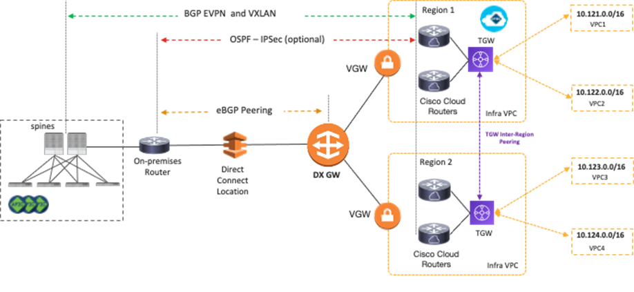
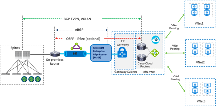
The overlay network between the on-premises ACI sites and cloud sites runs BGP EVPN as its control plane, and uses VXLAN encapsulation and tunneling as its data plane. VXLAN is used to identify the right routing domain when stretching a VRF across an on-premises Cisco ACI fabric and the cloud platforms. Tenant host routes and prefix routes are exchanged between the two sites as BGP EVPN route type-2 (host) and type-5 (prefix). The provisioning of this overlay network connectivity is automated by NDO.
You might need to adjust the Maximum Transmission Unit (MTU) size on the ACI control plane MTU policy for the BGP EVPN control plane and on your endpoints for the data plane to avoid fragmentation due to IPsec tunnels and VXLAN encapsulation overhead. Otherwise, fragmentation by devices in the network could degrade overall performance. For example, if the MTU of the involved endpoints is adjusted to 1300 bytes, this would account for the additional 50 bytes from VXLAN and around 100 bytes for the IPsec overhead to go over the Internet where the common value of MTU is 1500 bytes. If adjusting the MTU size on your endpoints is not allowed or preferable, then adjust the TCP Maximum Segment Size (MSS) on the Cisco Cloud Routers from Cisco Cloud Network Controller.
For configuration steps to change the TCP MSS value on the Cisco Cloud Routers from Cisco Cloud Network Controller, please refer to: https://www.cisco.com/c/en/us/td/docs/dcn/aci/cloud-apic/25x/installation/azure/cisco-cloud-apic-for-azure-installation-guide-250x/configuring-using-setup-wizard-250x.html
Cisco Multi-Cloud Networking Design Options
This section explains common Cisco Multi-Cloud Networking design use cases and the design considerations.
Table 2 summarizes the comparison of the design options covered in this section. The following sub-sections explain each design option and its considerations.
Table 2. Typical Design Options
| Use case |
Consideration |
| Application stretched across sites (intra-tenant)
|
An application can be implemented as groups of endpoints. The subnets must be different in the cloud sites and the on-premises site. |
| Tenants need to be stretched across sites (on-premises and cloud). Do not overlap subnets between VRFs. |
|
| Cloud to External networks through on-premises L3 Outsides (L3Outs) (Shared on-premises L3 Outsides (L3Outs)) |
The L3Out must be defined on a dedicated template for the on-premises ACI. The on-premises L3Out cannot be in the common tenant. |
| Azure uses Azure VPN Gateway or Express Route Gateway. AWS uses Transit Gateway. It is the responsibility of the end-user to manually configure branch devices on the external site. |
|
| BGP and IPsec must be enabled on the external device. The external device BGP ASN must be different from the BGP ASN of the Cisco Cloud Router in the cloud platforms. |
|
| No automation configuration at the SD-WAN side. SD-WAN administrators need to manually configure the routing and policy accordingly to align with Cisco Multi-Cloud Networking solution. |
|
| As of Cisco Cloud Network Controller release 25.1(1), third-party load balancer integration is available for Azure only. |
|
| As of Cisco Cloud Network Controller release 25.1(1), third-party firewall insertion is available for Azure only. |
|
| As of Cisco Cloud Network Controller release 25.1(1), multi node services insertion is available for Azure only. |
|
| As of Cisco Cloud Network Controller release 25.1(1), Cloud Native Service integration is available for Azure only. |
|
| Cisco Cloud Network Controller only imports networking objects such as VPCs/VNets. Cloud administrators still need to do certain manual configuration steps, such as creating or updating SGs/NSGs and route tables. |
|
| Brownfield Import feature with “Routing & Security” is required to automate routing and security configuration during switchover. |
|
| Brownfield Import feature with “Routing-only” is required. |
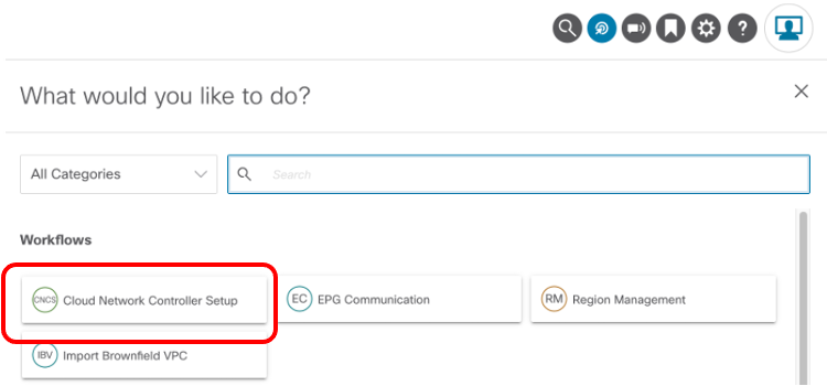
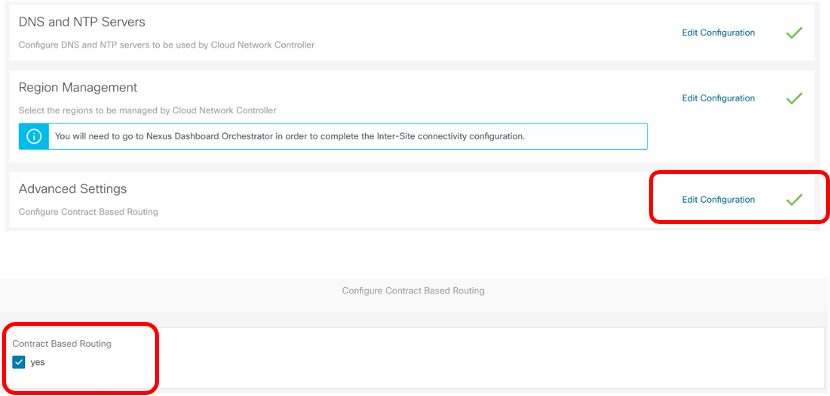
Unless otherwise indicated, this document is written based on the assumption that “Contract Based Routing” is enabled on both Cisco Cloud Network Controllers on AWS and Microsoft Azure. The “Contract Based Routing” option can be found using the following steps:
1. Click on Intent Button.
2. Click “Cloud Network Controller Setup”
3. Click “Edit Configuration” at “Advanced Setting” and turn on Contract Based Routing.
Use Case #1: Application Stretched Across Sites (Intra-Tenant)
This use case is one of the most common use cases, where an application is stretched across on-premises fabrics and public cloud platforms. The main benefits of this use case are workload flexibility and centralized policy control. An application tier, such as a web tier, can be deployed across on-premises fabrics and public cloud platforms to provide better resiliency. Meanwhile, the security policy between the web tier and other tiers, such as a database tier, is maintained consistently regardless of workload location.
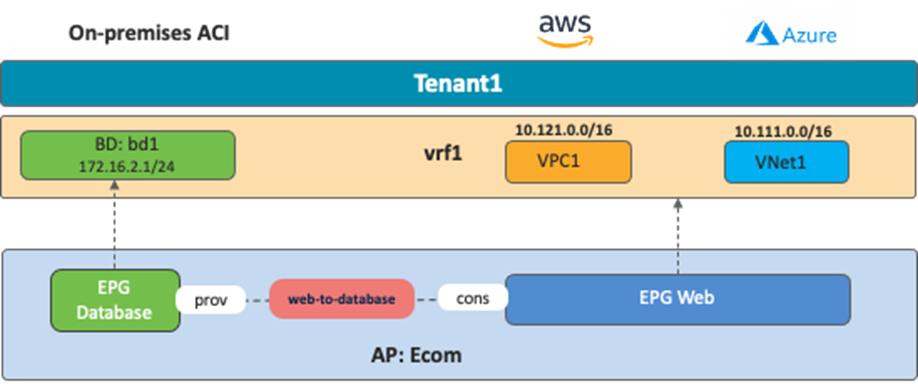
The following figure illustrates an example of this use case. In this example, a sample application “Ecom” comprises a database tier and a web tier:
· The database tier is represented by the EPG “Database”, provisioned on the on-premises ACI fabric.
· The web tier is represented by the EPG “Web”, residing on both AWS and Microsoft Azure.
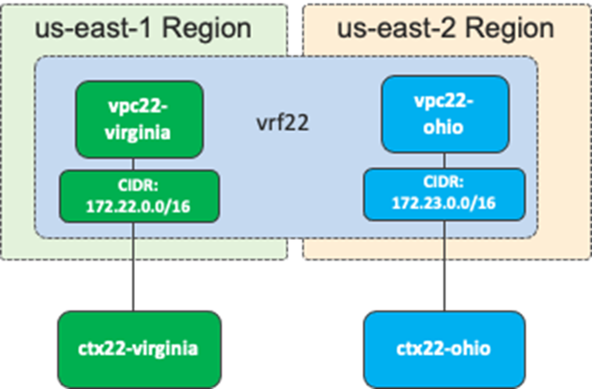
In this use case, a VRF is stretched across three environments (on-premises ACI, AWS, and Microsoft Azure) to enable Layer 3 connectivity between them. In the following example, the VRF is mapped to a VPC on AWS and to a VNet on Microsoft Azure, although one VRF in ACI can technically be mapped to multiple VPCs/VNets. For example, it is possible to create one VRF on ACI, and that VRF could map to two VPCs on AWS, providing that the VPCs are in different regions, as shown in the following figure.
Communication within an EPG doesn’t require a contract even if endpoints are in different environments. For example, an AWS instance in EPG “Web” can talk to an Azure VM in EPG “Web” without any contract. If an EPG is stretched, routing and security policy configurations required for the communication will be deployed on each environment through NDO automatically.
Although AWS and Microsoft Azure have different ways of implementation for both internal and external routing, Cisco Multi-Cloud Networking solution normalizes the complexity by bringing consistent network and security policy models across different environments that simplify operations in hybrid multi-cloud environments. An administrator creates VRFs, EPGs, and contracts between EPGs on NDO, which, through the interactions with Cisco APIC and Cloud Network Controller, will then take care of deployments across these environments.
Considerations: In this use case, an application tier (such as a Web EPG) is stretched across the public cloud platforms. This requires the provisioning of the Web EPG configuration in a template that is associated with both the AWS and Azure cloud sites (for example, in a “stretched template”). On NDO, the template represents the atomic unit of configuration provisioning (configuration changes can be deployed one template at a time), so any change in the stretched template will be concurrently pushed to all the sites where the stretched template is applied. Consequently, only the features that are supported on both public cloud sites can be used in this type of stretched template. For example, Cloud Service EPG cannot be configured in a stretched template because it is a functionality supported only on a cloud site with Microsoft Azure at this time.
Use Case #2: Shared Services in Hybrid Multi-Cloud Environment
This section explains a use case where a common provider resource is shared with different consumers, which is called a shared service. Examples of a shared service include common databases, DNS, and AD services, which are shared with users and applications.
From a network design perspective, a shared service can be implemented through inter-VRF under certain conditions:
· Only non-overlapping IP addresses can be leaked between the VRFs.
· Subnets leaked from multiple consumer VRFs to the provider VRF must be unique and cannot overlap.
From a contract design perspective, inter-VRF and inter-tenant contracts have the following guidelines:
· Contract scope must be set to “tenant” for an inter-VRF intra-tenant contract.
· Contract scope must be set to “global” for an inter-tenant contract.
· The consumer and provider VRFs don’t have to be stretched across sites (they can be site local).
· If it’s an inter-tenant contract across sites, both sites must be associated to both tenants in the NDO “Tenants” configuration for NDO to have the right credentials to manage the cloud environments, whereas the tenants don’t have to be deployed to both sites through the “Schema” configuration. For example:
o EPG1 in VRF1 in the on-premises ACI site tenant1.
o EPG2 in VRF2 in the cloud site tenant2.
o Both the on-premises ACI site and the cloud site are associated to tenant1 and tenant 2 in the NDO “Tenants” configuration.
o The schema template1 for tenant1 is deployed on the on-premises ACI site only, and template2 for tenant2 is deployed on the cloud site only.
Because of these considerations, it is important to understand how subnet leaking and route propagation work across sites in Cisco Multi-Cloud Networking solution and supported contract configurations. The following sub-sections explain intra-VRF route propagation, inter-VRF route leaking, and inter-VRF and inter-tenant contract configuration examples.
This sub-section explains intra-VRF route propagation across sites.
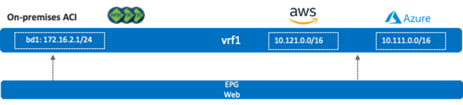
The following figure illustrates an intra-VRF route propagation example where a VRF is stretched across multiple sites including AWS, Microsoft Azure and an on-premises ACI site. In this example, vrf1 is also deployed on the on-premises ACI site, but no bridge domain is deployed on the on-premises ACI site yet. As a result, Cisco Cloud Routers on both AWS and Microsoft Azure will have two routes in their vrf1 routing table (10.111.0.0/16 and 10.121.0.0/16 in this example).

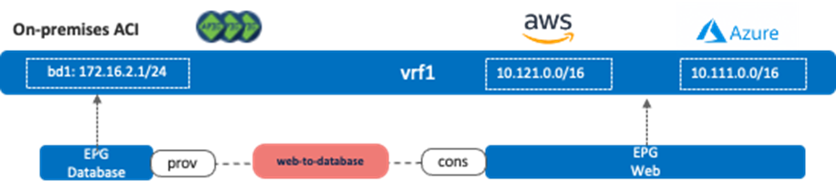
Next, assume there is a bridge domain (bd1) whose BD subnet is 172.16.2.1/24, and that bridge domain is deployed on the on-premises ACI site. If an EPG in bd1 is stretched across the on-premises ACI site and a cloud site, or an EPG in bd1 has a contract with another EPG in a cloud site, the 172.16.2.0/24 subnet is advertised to the Cisco Cloud Routers.
The following figure illustrates the first example where the existence of a stretched EPG has the route from the on-premises ACI site propagate to the cloud sites.
The following figure illustrates the second example with a contract between a non-stretched on-premises EPG (EPG “Database”) and another non-stretched cloud EPG (EPG “Web”).
Inter-VRF and Inter-Tenant Contract Configuration Examples
This sub-section explains inter-VRF route leak behavior, and inter-VRF and inter-tenant contract configuration examples.
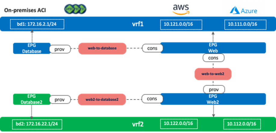
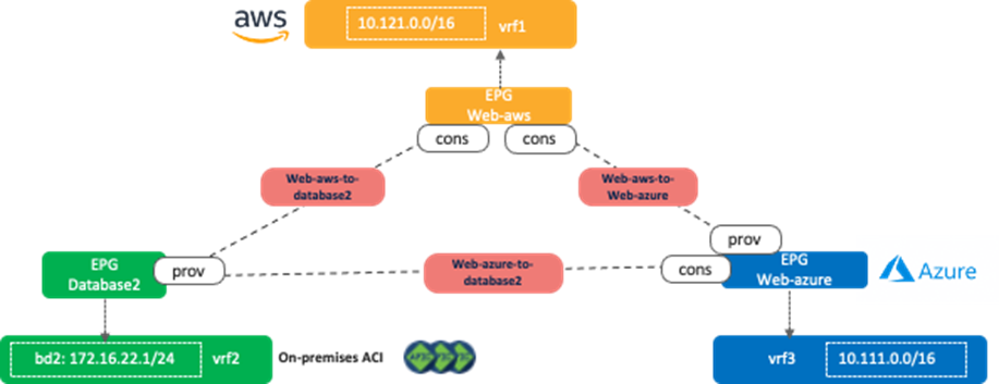
The following figure illustrates scenario 2a, where VRFs are stretched across sites. If it’s an inter-tenant contract, both tenants are stretched across sites (both tenants are deployed on all the sites). In this example, EPG “Web” and “Web2” are deployed on the cloud sites only, and EPG “Database” and “Database2” are deployed on the on-premises ACI site only. In this scenario, the following communication are allowed because of the contracts between them:
· Endpoints in EPG Web and endpoints in EPG Database
· Endpoints in EPG Web2 and endpoints in EPG Database2
· Endpoints in EPG Web and endpoints in EPG Web2
Other inter-EPG communications are not allowed even though the routes exist. For example, an endpoint in EPG Web and an endpoint in EPG Database2 cannot communicate with each other.
It’s important to note that inter-VRF route leak behavior in Cisco Multi-Cloud Networking solution is a bit different from inter-VRF route leak within an on-premises ACI fabric that leaks specific subnets only to the other VRF. In the case of Cisco Multi-Cloud Networking solution, all of the CIDRs and routes are leaked to the other VRF if there is an inter-VRF contract. For example, even if the inter-VRF contract between vrf1 and vrf2 are only between EPG Web and Web2, vrf1 and vrf2 have the following routes leaked from the other VRF:
· vrf1: 10.122.0.0/16 (vrf2 CIDR on AWS), 10.112.0.0/16 (vrf2 CIDR on Azure), and 172.16.22.0/24 (bd2)
· vrf2: 10.121.0.0/16 (vrf1 CIDR on AWS), 10.111.0.0/16 (vrf2 CIDR on Azure), and 172.16.2.0/24 (bd1)
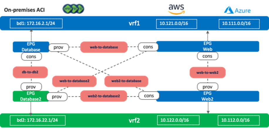
The following figure illustrates scenario 2b, which has more contracts compared to scenario 2a. In this case, all inter-EPG communication across sites is allowed (for example, endpoints in EPG Web and endpoints in EPG Database2 can communicate with each other).
The following figure illustrates scenario 2c, where a consumer or a provider VRF is not stretched across the on-premises ACI site and the cloud sites. Consumer VRF “vrf1” is deployed on AWS and Microsoft Azure only, and provider VRF “vrf2” is deployed to the on-premises ACI site only. If it’s an inter-tenant contract, both the on-premises ACI site and the cloud sites must be associated to both tenants in the NDO “Tenants” configuration, though the tenants don’t have to be deployed on all sites. 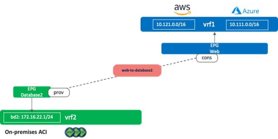
The following figure illustrates scenario 2d, where three VRFs are site local. Similar to the considerations in scenario 2c, if it’s an inter-tenant contract, all sites must be associated to all tenants in the NDO “Tenants” configuration, though the tenants don’t have to be deployed on all sites.
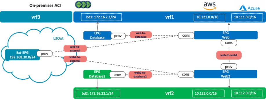
The following figure illustrates scenario 2e. This is one of the typical shared service use cases where a shared service resides in an external network that is represented as an external EPG in the on-premises ACI fabric. The Layer 3 Out (L3Out) must be configured in one of the VRFs (vrf1 in figure 37) or in a separate VRF (vrf3 in figure 38). It cannot be defined in both vrf1 and vrf2.
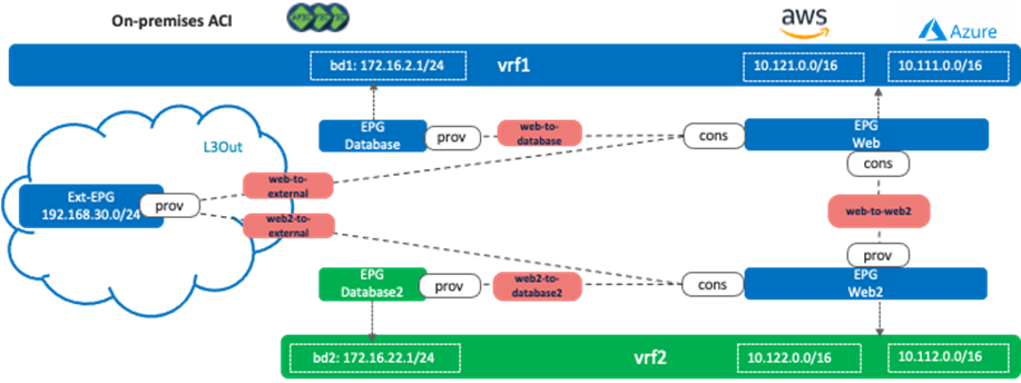
The reason why it cannot be in both vrf1 and vrf2 is because it could cause overlapping routes. As described in scenario 2a, in the case of Cisco Multi-Cloud Networking solution, all the CIDRs and routes are leaked to the other VRF if there is an inter-VRF contract. The following figure illustrates an unsupported example. Even if the inter-VRF contract between vrf1 and vrf2 are only between EPG Web and Web2, vrf1 and vrf2 have the following routes leaked from the other VRF:
· vrf1: 10.122.0.0/16 (vrf2 CIDR on AWS), 10.112.0.0/16 (vrf2 CIDR on Azure), 172.16.22.0/24 (bd2), and 192.168.30.0/24
· vrf2: 10.121.0.0/16 (vrf1 CIDR on AWS), 10.111.0.0/16 (vrf2 CIDR on Azure), 172.16.2.0/24 (bd1), and 192.168.30.0/24
The issue is that both VRFs have the 192.168.30.0/24 route leaked within its VRF and leaked from the other VRF, which results in an overlapping subnet.
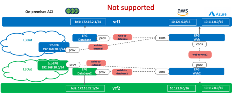
Note for advanced readers: If there is that type of overlapping route, traffic could be dropped on the on-premises ACI. For example, traffic from a cloud endpoint in vrf1 to the external network (192.168.30.0/24) is forwarded to one of the Cisco Cloud Routers, which potentially sends traffic to the on-premises ACI fabric using the route via vrf2 instead of vrf1, which means traffic arrives on the on-premises ACI fabric using the vrf2 VNID. As a result, the ACI leaf switch looks up the zoning rules for vrf2, which doesn’t have a permit rule for the EPG in vrf1.
The configuration considerations on an external EPG and a cloud EPG will be explained in Use Case #3-2.
Use Case #3: Cloud to Internet/External Networks
Use Case #3-1: Cloud to Internet Using Cloud Native Routing Functionality
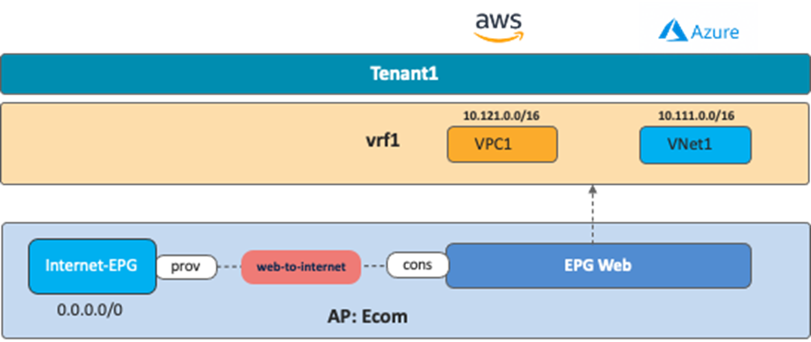
This is a common use case where cloud workloads access the Internet directly using cloud native routing functionality, such as Internet Gateway in AWS and default system route in Microsoft Azure. The main benefits of this use case are simplification and scalability. It is simple to configure, and public cloud platforms provide high scale Internet access directly from its VPC (on AWS) and VNet (on Microsoft Azure).
The following figure illustrates an example where the EPG “Web” and the external EPG “Internet-EPG” (that uses the 0.0.0.0/0 IP selector) are defined in the tenant for the Application profile “Ecom”. To allow Internet access initiated from the cloud workload, you must apply a contract between EPG “Web” as the consumer and “Internet EPG” as the provider.
In this case, traffic originated by endpoints on the Internet and destined to the cloud endpoints in the EPG Web (the consumer) is not permitted because a contract for a cloud site creates a permit rule for the traffic from the consumer to the provider only. The return traffic from the provider to the consumer is then automatically permitted (even though there is no explicit permit rule) because the consumer to the provider traffic was previously observed. Thus, if there is a possibility that endpoints on the Internet initiate communication with cloud endpoints in the EPG Web, then the Internet-EPG needs to be the consumer and the EPG Web needs to be the provider of the contract.
Use Case #3-2: Cloud to External Networks Through On-Premises L3 Outsides (L3Outs)
This use case is used when there is a need to provide connectivity between an external network and public cloud resources through an on-premises ACI fabric. The external network can be a WAN, a simple branch, or the Internet connectivity.
The benefits of this use case are the consistent security policy model and secured connectivity. We can apply policy to external networks that have routed connectivity to the on-premises ACI site as if they were connected as regular endpoints. It is possible to use an on-premises firewall to enforce certain security policies for traffic going in and out of a cloud site.
The following figure illustrates an example where the Layer 3 Outside “L3Out” and external EPG “Ext-EPG” are defined in the tenant for the Application profile “Ecom”. The purpose of this use case is to provide connectivity between the EPG “Web” provisioned on the cloud sites and external network resources accessible via the on-premises L3Out. You must therefore apply a contract between the EPG “Ext-EPG” (associated to the on-premises L3Out) and the EPG “Web” in the cloud. A contract between the EPG “Database” and the external EPG “Ext-EPG” is optional.
. 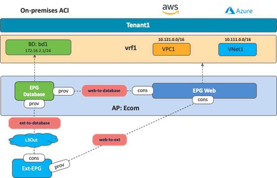
This use case has the following guidelines:
· You must configure the L3Out along with the associated external EPG(s) in a dedicated template mapped to the on-premises ACI site.
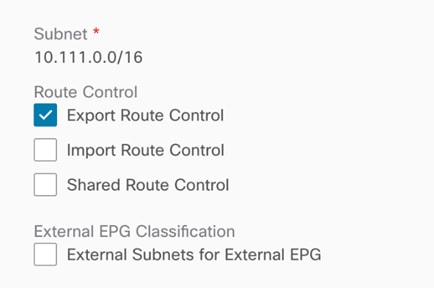
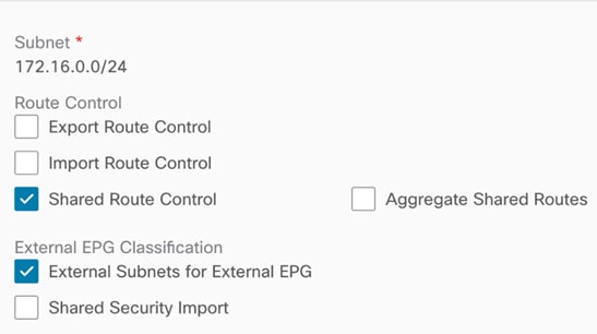
· To advertise cloud EPG subnets (the subnet where the Web EPG resides in this specific example) out of the on-premises L3Out, you must configure the cloud CIDR prefix under the Ext-EPG and you must set the flag “Export Route Control”. (Figure 42).
· To advertise external prefixes learned via the on-premises L3Out connection toward the cloud sites, you must set “Shared Route Control” and “External Subnets for External EPG” at the external EPG (Figure 43).
Use Case #4: Connect to External Site Using Cloud Native Routing Service
The purpose of this use case is to use cloud native routing services, such as Azure VPN and ExpressRoute Gateway and AWS Transit Gateway, to connect to external sites.
· For Azure, the cloud administrator must create the Azure VPN/ExpressRoute Gateway directly from the Microsoft Azure Portal.
· For AWS, Cisco Cloud Network Controller automates the Transit Gateway creation as part of the Cisco Cloud Network Controller First Time Setup process.
BGP is used as the dynamic protocol between the external devices at the branches to cloud native routing services, and IPsec is used as the underlay tunnel. Security rules are enforced at each cloud site using SG rules on AWS and NSG rules on Microsoft Azure.
The table below summarizes the differences between Microsoft Azure and AWS in terms of providing external connectivity from cloud platforms to external sites under Cisco Cloud Network Controller's purview.
Table 3. Comparison Between Microsoft Azure VPN/ExpressRoute Gateway and AWS Transit Gateway from an External Connectivity Perspective
Use Case #4-1: Connect to External Site using Microsoft Azure VPN Gateway and ExpressRoute Gateway
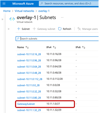
This use case is one of the options to connect external sites (such as branch networks) directly to Microsoft Azure. A gateway subnet that is required by Microsoft Azure for gateway deployment is deployed automatically by Cisco Cloud Network Controller during the First Time Setup. Both Azure ExpressRoute Gateway and Azure VPN Gateway can be used for connectivity from a branch network to Microsoft Azure.
· Azure ExpressRoute Gateway provides direct connectivity to Microsoft Azure through Microsoft’s global network. All transferred data is not encrypted and does not go over the Internet.
· Azure VPN Gateway provides a secured connectivity to Microsoft Azure over the Internet. All transferred data is encrypted in private tunnels and goes over the Internet.
In this use case, the cloud administrator creates the Microsoft Azure VPN Gateway (or ExpressRoute Gateway) directly from the Microsoft Azure portal. The cloud administrator also creates the Local Network Gateway (which is a Microsoft Azure term representing an external device). Upon filling in the required information, such as the BGP ASN of the VPN Gateway, external device, and IPsec options, Microsoft Azure will export the configuration templates based on the external device types (Microsoft Azure supports various device types, such as Cisco ASA, ISR, etc.). Configuration templates contain required information, such as the configurations of the IPsec tunnels and BGP. Based on the configuration template, it is the responsibility of the network administrators to configure their external device to establish the IPsec and BGP session between the external device and the Azure VPN Gateway.
From an external site to a cloud site, the branch subnet routes behind the external device will be advertised to the Azure VPN Gateway through BGP. The Azure VPN Gateway then propagates the branch subnet routes to the user VNet (also called the spoke VNet) using VNet peering with gateway transit (also referred to as transit peering). VNet peering with gateway transit is automatically enabled by Cisco Cloud Network Controller.
In the reverse direction from the cloud site to the external site, the user VNet CIDR will be propagated to Azure VPN Gateway, then Azure VPN Gateway advertises it to the external device through BGP.
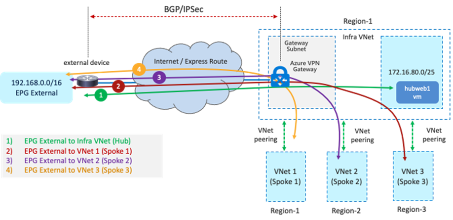
The main benefit of this use case is deployment flexibility. In some design scenarios, branch sites are distributed in different physical regions and it is not efficient for all the branch sites to get connected to the cloud platforms through on-premises ACI fabrics. In that scenario, this use case enables customers to leverage Azure ExpressRoute Gateway or VPN Gateway as a termination point to bring connectivity directly from external devices deployed in branch sites to cloud platforms, with Cisco Multi-Cloud Networking solution still providing a consistent policy model.
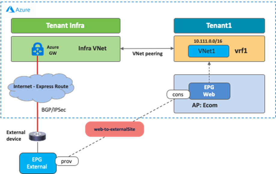
The following figure illustrates an example of this scenario. In this example, the external EPG logical object (Ext-EPG) is used to classify all the endpoints belonging to the subnets outside of Microsoft Azure (for example, the external sites) that need to communicate with the EPG Web provisioned in the cloud. The contract used between the Ext-EPG and the EPG Web must be set to “global” scope since the external EPG is deployed in the infra tenant while the EPG “Web” is deployed in a user tenant.
Keep in mind that the branch device must enable IPsec and BGP. Because Microsoft Azure ExpressRoute Gateway and VPN Gateway support a limited number of routes, please make sure to check Microsoft Azure documentation for the latest scale number.
Use Case #4-2: Connect to External Site Using AWS Transit Gateway
This use case is one of the options to connect external sites, such as branch networks, directly to AWS through Transit Gateway, which is an AWS native networking service. Transit Gateway is deployed in the infra VPC automatically by Cisco Cloud Network Controller during the First Time Setup process. Starting from the 25.0(2) release, Cisco Cloud Network Controller can initiate IPsec tunnels and BGP sessions from AWS Transit Gateway to external sites. The Cisco Cloud Network Controller admin just needs to create external connectivity with proper configurations, including the public IP address and the BGP ASN of the branch devices at the external sites, and common IPsec parameters such as the IKE and the pre-shared key for the AWS Transit Gateway and the branch device. It is responsibility of the network administrator to manually configure the external device by downloading the configuration files and enabling connectivity through the Cisco Cloud Network Controller.
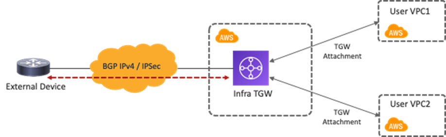
The main benefit of this use case is flexibility on the network automation deployment. In this use case, Cisco Cloud Network Controller automates the TGW tunnels configuration and the TGW route table creation. Moreover, Cisco Cloud Network Controller automate route propagation between the external network TGW route table and the user VPC route table. You do not have to deploy Cisco Cloud Routers in all regions; instead, by leveraging the AWS Transit Gateway VPN Attachment, you can provide connectivity from branches at physical locations to cloud workloads that even reside in different AWS regions. A consistent policy model is also maintained since the external network at the external site is treated as an external EPG using subnet-based selectors, and contracts can be applied between the external EPG and the cloud EPG.
The following figure illustrates an example configuration. In this example, the external EPG is for the subnet outside of AWS. The contract scope must be set to "global” since the external EPG is deployed in the infra tenant and the EPG “Web” is deployed in a user tenant. 
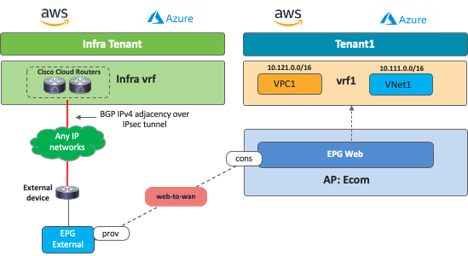
Use Case #5: External Connectivity to WAN, Branch, or Non-ACI Site
This use case is based on the External Connectivity feature from the Cisco Cloud Router that is supported from Cloud APIC release 25.0(1) for both AWS and Microsoft Azure. This use case is used when there is a need to connect external IP networks directly to cloud platforms (AWS and Microsoft Azure) without going through on-premises ACI fabrics.
The difference between this use case and Use Case #4 is whether Cisco Cloud Routers or cloud native routing services are used as the termination points. One of the benefits of this use case is the routing scale, since the Cisco Cloud Router supports a higher number of routes compared to cloud native services. Routing devices in the external networks must use BGP and IPsec to establish IP connectivity to Cisco Cloud Routers in the infra tenant. As a centralized orchestrator, NDO talks to a Cloud Network Controller to configure the Cisco Cloud Routers and generates configuration templates for the external devices. Cisco Cloud Routers can connect to any networks outside of the cloud platform if external devices support BGP and IPsec.
The following figure illustrates an example configuration. In this example, the external network is classified as a subnet outside of Microsoft Azure. The contract must be set to the Global scope since the external EPG is deployed in the infra tenant and an EPG “Web” is deployed in a user tenant.
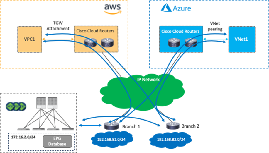
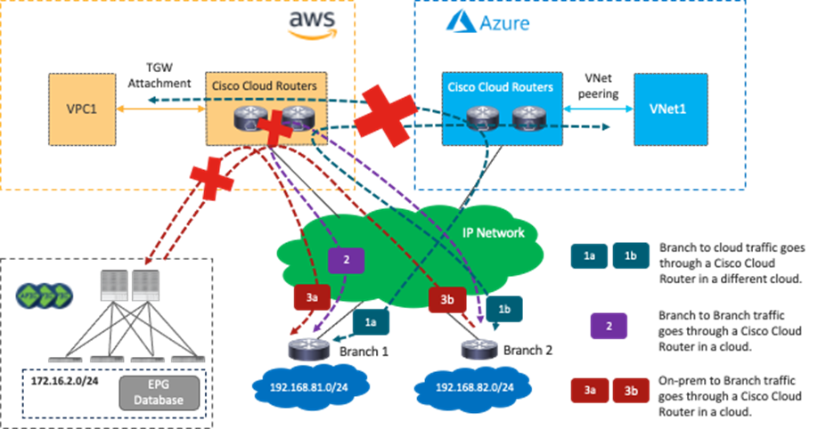
This use case has the following guidelines:
· Cisco Cloud Routers managed by Cisco Multi-Cloud Networking solution in one cloud platform cannot be a transit for the branch that connects to Cisco Cloud Routers on other cloud platforms. For example, traffic from an endpoint in the branch cannot reach an endpoint in the AWS site through a Cisco Cloud Router in a Microsoft Azure site.
· Cisco Cloud Routers cannot be a transit for branches, which means traffic from branch 1 cannot reach branch 2 through Cisco Cloud Routers.
· Cisco Cloud Routers cannot be a transit for branches and an on-premises ACI site, which means traffic from one branch cannot reach the on-premises ACI site through Cisco Cloud Routers.
The figures below illustrate supported traffic flows and unsupported traffic flows.
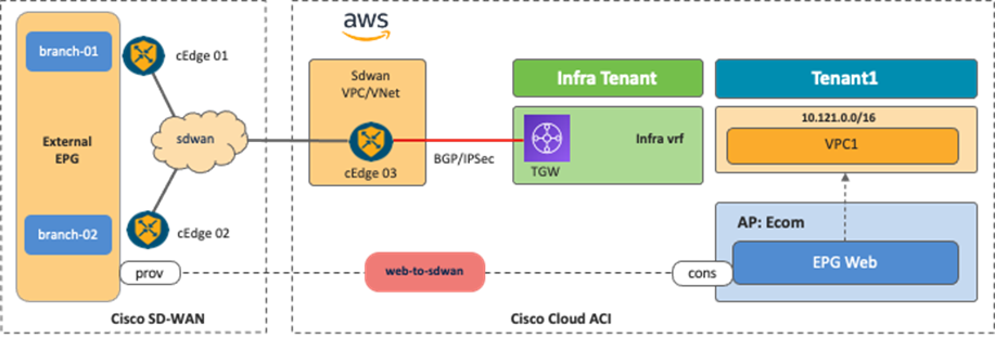
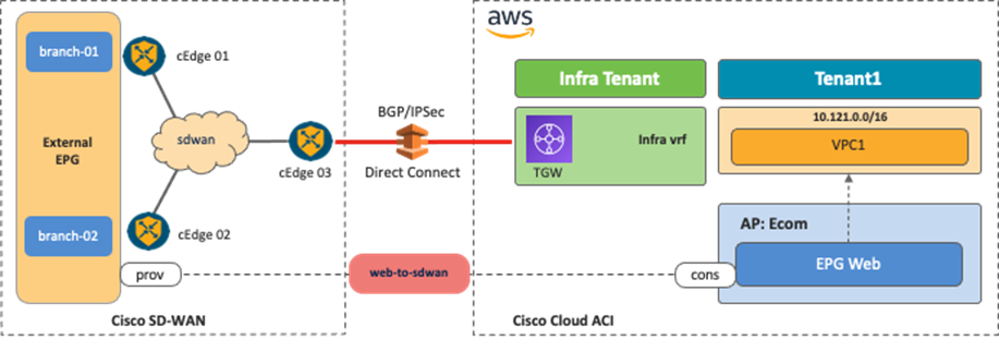
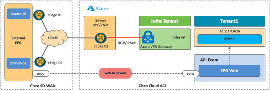
Use Case #6: Inter-Working with SD-WAN Solutions
By leveraging the External Connectivity feature from Cisco Cloud Routers that is supported in Cloud APIC release 25.0(1), and as described in Use Case #4, Cisco SD-WAN or any SD-WAN solution can inter-work with Cisco Multi-Cloud Networking to provide connectivity and segmentation from branch networks to cloud workloads.
The following figures illustrate the examples of this scenario. From the Cisco Multi-Cloud Networking solution perspective, the SD-WAN branch networks are external EPGs. SD-WAN edge devices can be deployed anywhere, even on a public cloud platform. The communication channel from the SD-WAN edge device to the Cisco Cloud Router could be the Internet, Microsoft Azure Express Route, AWS Direct Connect, etc.
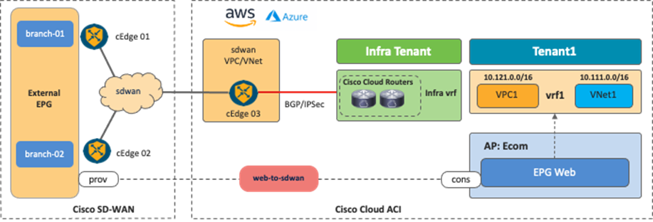
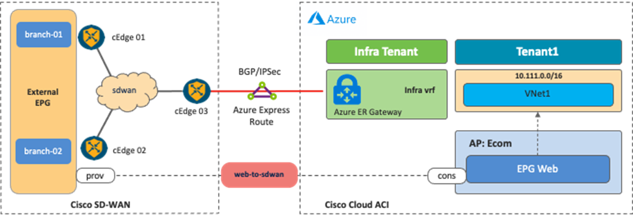
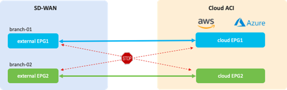
It is possible to fine-tune the external EPG classification to have end-to-end segmentation from SD-WAN branch networks to cloud workloads. In this example scenario, the branch-01 network subnet is classified as external EPG1, and the branch-02 network subnet is classified as external EPG2. By using separate external EPGs, different security policies can be applied based on the branch network subnets. For example, a contract can be applied between external EPG1 and cloud EPG1, and another contract can be applied between external EPG2 and cloud EPG2. With this configuration, branch-01 can communicate with workloads in cloud EPG1, but not cloud EPG2, whereas branch-02 can communicate with workloads in cloud EPG2, but not cloud EPG1. Security policies are programmed as SG rules on AWS and NSG rules on Microsoft Azure respectively by Cloud Network Controller if contracts are applied.
This use case has the following guidelines:
· At this time, Cisco SD-WAN controllers and NDO work independently. NDO automates the configuration of the Cisco Cloud Routers and generates configuration templates for external devices, which include BGP and IPsec parameters. Based on the configuration templates, the Cisco SD-WAN administrator can configure cEdge devices to establish IPsec and BGP sessions to the Cisco Cloud Routers.
· The BGP ASNs of the SD-WAN edge devices and the Cisco Cloud Routers must be different.
Use Case #7: Load Balancer Insertion
In this use case, a load balancer is inserted between EPGs using contracts with service graphs. Cisco Multi-Cloud Networking solution supports cloud native load balancers provided by AWS and Microsoft Azure, and third-party load balancers such as F5 BIG-IP Virtual Edition, Citrix ADC VPX, etc.
The following table summarizes the differences between what Cisco Multi-Cloud networking solution supports for cloud native load balancers and third-party load balancers.
Table 4. Comparison Between Cloud Native Load Balancers and Third-Party Load Balancers
The main difference between the two is that Cisco Cloud Network Controller manages the creation and configuration of cloud native load balancers in addition to the routing and security policy in the cloud networking, whereas Cisco Cloud Network Controller doesn’t manage third-party load balancers. Because Cisco Cloud Network Controller doesn’t configure the third-party load balancers, the ability to dynamically add or remove provider endpoints as targets of the VIP on the load balancer is available for cloud native load balancers only.
This document explains the load balancer insertion use cases discussed below, describing traffic flows and associated deployment considerations for each option:
· Public (external) load balancer: North-south traffic flows between the external network, such as the Internet, and the provider endpoints that are part of the same VRF. Public load balancers own public IP addresses for external facing and load balance traffic to provider endpoints in the cloud platforms.
· Private (internal) load balancer: East-west traffic flows between consumer and provider endpoints that are in the same VRF. Private load balancers own private IP addresses and are used to load balance traffic to provider endpoints in the cloud platforms. A load balancer frontend can be accessed from an on-premises network in a hybrid scenario.
The following figures illustrate examples of the design with public and private (internal) load balancers.
· The public load balancer is inserted in the contract “external-to-web” between an external EPG “internet” and EPG “web” in the same tenant.
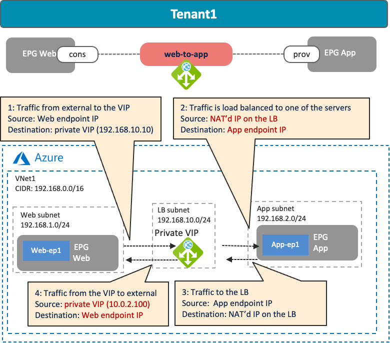
· The private load balancer is inserted in the contract “web-to-app” between EPG “web” and EPG “app” in the same tenant.
Though the figures use one VRF (VPC or VNet) for the private load balancer, inter-VNet design is also supported for Azure. Unlike an on-premises ACI fabric, a cloud site doesn’t use traffic redirection for load balancer designs, so the assumption is that SNAT must always be enabled to ensure that return traffic is steered to the load balancer before reaching the client that initiated the connection.

The cloud native load balancer use case has the following guidelines:
· SNAT is enabled on ALB but not on NLB.
· Cisco Cloud Network Controller supports VM instances and VM scale sets as backend targets of the Azure Load Balancer (NLB) and Application Gateway (ALB). Release 25.0(2) or later is required for VM scale sets as backend targets.
· Cisco Network Controller supports Amazon EC2 instances as backend targets of the AWS Application Load Balancer (ALB). Auto Scaling group is not supported at this time.
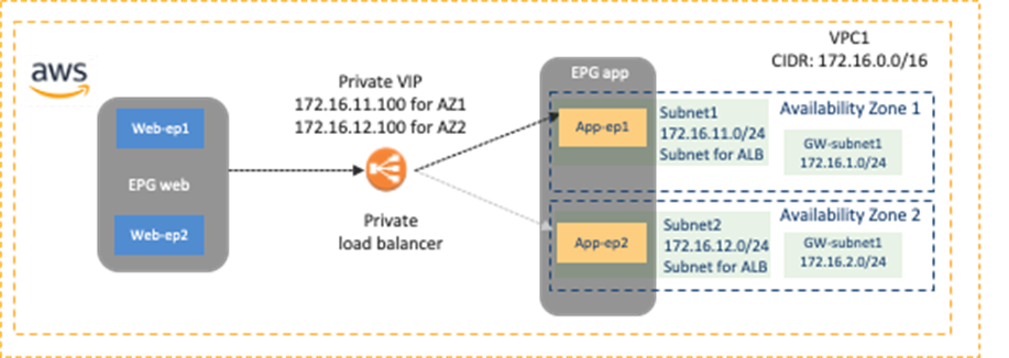
· AWS ALB: The consumer and the provider EPGs must be in the same VPC. ALB is associated with two availability zones of that same VPC where the target EC2 instances reside. For each availability zone, you must select one subnet in the availability zone for the ALB and the subnet must not be the subnet that is used for TGW VPC attachment. (Based on the recommendation of Transit gateway design practices, Cisco Multi-Cloud Networking solution requires one dedicated gateway subnet for each Availability Zone to attach the VPC to a Transit Gateway.) Figure 46 below illustrates an example scenario.
· Azure NLB: NLB and its target (the provider EPG) must be in the same VNet. NLB must be in a dedicated subnet.
· Azure ALB: ALB must be in either the hub VNet or the provider VNet, which is reachable from the consumer and the provider. ALB must be in a dedicated subnet.
· Dynamic IP or static IP assignment
o Public and Private/Internal AWS Load Balancer (Azure ALB):
§ Dynamic IP is used.
o Public Azure Application Gateway (Azure ALB):
§ In the case of standard V1, dynamic public IP is used.
§ In the case of standard V2, static public IP is used.
o Private/Internal Azure Application Gateway (Azure ALB):
§ In the case of standard V1, both static and dynamic private IP are supported because Azure supports both.
§ In the case of standard V2, only static private IP is supported because Azure doesn’t support dynamic private IP for standard V2.
· Inter-site traffic is NOT supported at this time. For example:
o When the consumer is in an AWS site and the provider is in a Microsoft Azure site.
o When the consumer is in an ACI on-premises site and the provider is in a Microsoft Azure site.
The third-party load balancer use case has the following guidelines:
· At this time, Cisco Multi-Cloud Networking solution only supports third-party load balancers insertion with Microsoft Azure.
· Third-party load balancers must be in the hub VNet or the provider VNet, which is reachable from the consumer and the provider.
· SNAT must be enabled on the third-party load balancers (traffic redirect for the return traffic is not supported at this time)
· Third-party load balancer doesn’t support the following design options:
o One-arm mode
o Redirection
o DSR (Direct Server return)
o Alien VIP range that is outside of the load balancer interface subnet.
o Active-Standby HA
· Inter-site traffic is NOT supported at this time. For example:
o When the consumer is in an AWS site and the provider is in a Microsoft Azure site.
o When the consumer is in an ACI on-premises site and the provider is in a Microsoft Azure site.
Unless it’s specifically mentioned, the following sub-section uses Cisco Multi-Cloud Networking solution with Azure using an Azure Application Gateway with SNAT as an example.
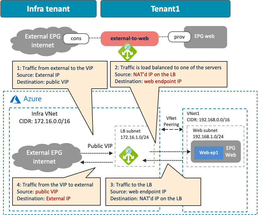
Use Case #7-1: Public (External) Load Balancer
The following figures illustrate examples of a design with a public load balancer. A typical use case of this design is for a public service exposed to the external network, such as the Internet. In this example, the external EPG is the consumer, and the cloud EPG “Web” is the provider of the contract. The load balancer has one interface. Traffic from the consumer to the VIP arrives to the load balancer. After the load balancer changes the source and the destination IP addresses, the traffic is forwarded to one of the endpoints in the cloud EPG “Web”. The return traffic comes back to the load balancer that owns the NAT’d IP address. After the load balancer changes the source and the destination IP addresses, traffic is forwarded back to the external endpoint.
In addition to the guidelines provided in the load balancer insertion considerations in the previous sub-section, this use case has the following guidelines:
· Though this example uses a load balancer in the infra VNet, other combinations are also supported in Cisco Multi-Cloud Networking solution with Azure, such as the following:
o The consumer external EPG, the load balancer, and the provider cloud EPG in the infra VNet.
o The consumer external EPG and the load balancer in the infra VNet, and the provider cloud EPG in a user VNet.
o The consumer external EPG in the infra VNet, and the load balancer and the provider cloud EPG in a user VNet.
· Cisco Multi-Cloud Networking solution with AWS using ALB supports the intra-VPC design only, which means the consumer, the load balancer (ALB), and the provider must be in the same VPC.
Use Case #7-2: Private (Internal) Load Balancers
The following figures illustrate examples of a design with a private load balancer. A typical use case of this design is for a service exposed to the other private networks. In this example, cloud EPG “Web” is the consumer, and cloud EPG “App” is the provider of the contract. The load balancer has one interface. Traffic from the consumer to the VIP arrives to the load balancer. After the load balancer changes the source and the destination IP addresses, the traffic is forwarded to one of the endpoints in the cloud EPG “App”. The return traffic comes back to the load balancer that owns the NAT’d IP address. After the load balancer changes the source and the destination IP addresses, traffic is forwarded back to the external endpoint.
In addition to the guidelines provided in the load balancer insertion considerations in the previous sub-section, this use case has the following guidelines:
· Though this example uses an intra-VNet design, other combinations are also supported in Cisco Multi-Cloud Networking solution with Azure, such as the following:
o The consumer cloud EPG, the load balancer, and the provider cloud EPG in the same VNet.
o The consumer cloud EPG in the consumer VNet, and the load balancer and the provider cloud EPG in the provider VNet.
o The consumer cloud EPG in the consumer VNet, the load balancer in the infra VNet, and the provider cloud EPG in the provider VNet.
· Cisco Multi-Cloud Networking solution with AWS using ALB supports the intra-VPC design only, which means the consumer, the load balancer (ALB), and the provider must be in the same VPC.
Use Case #8: Firewall Insertion
This use case describes a firewall insertion between EPGs using contracts with a service graph. At this time, this is supported on Cisco Multi-Cloud Networking solution with Microsoft Azure only. Cisco Multi-Cloud Networking solution supports third-party firewalls such as Cisco Adaptive Security Virtual Appliance (ASAv), Cisco Firepower NGFW Virtual (NGFWv), etc. Cloud native security services, such Azure Firewall and Azure Web Application Firewall (WAF), are currently not supported.
Cisco Cloud Network Controller manages the routing and security policy to insert firewalls in the cloud networking; however, Cisco Cloud Network Controller doesn’t manage third-party firewalls (just as Cisco Cloud Network Controller doesn’t manage third-party load balancers). To redirect traffic to the firewall, Cisco Cloud Network Controller configures UDRs (User Defined Routes) based on the contract with the service graph.
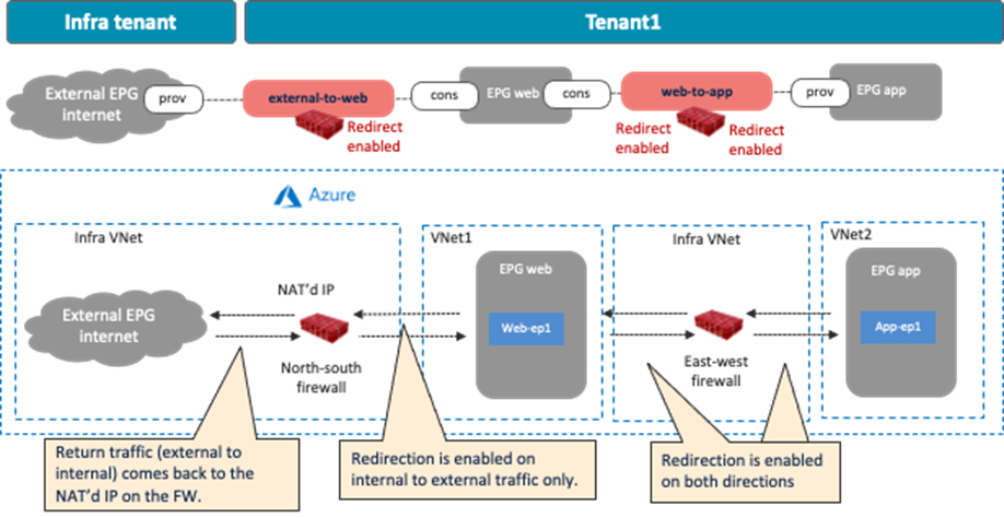
This section explains the firewall insertion use cases discussed below, describing traffic flows and associated deployment considerations for each option:
· Firewall insertion with NAT: North-south traffic flows initiated by cloud endpoints to the external network. The firewall translates the private IP address of the cloud endpoint to the public IP address.
· Firewall insertion without NAT: East-west traffic flows between consumer and provider endpoints that are in different VRFs.
The following figures illustrate examples of a design with firewalls. The north-south firewall is inserted in the contract “external-to-web” between an external EPG “internet” and the EPG “Web”. Traffic redirection is enabled for traffic going to the external site only. The east-west firewall is inserted in the contract “web-to-app” between the EPG “Web’ and the EPG “App”. Traffic redirection is enabled for both directions.
Firewall insertion has the following guidelines:
· For inter-VNet traffic, VNet peering is required.
· The redirect destination (the firewall interface IP address in this example) must be in the hub VNet (the infra VNet).
· Firewall interfaces must be in dedicated subnets that are different from the subnet where the cloud EPG reside.
· Inter-site traffic is NOT supported at this time. For example:
o When the consumer is in an AWS site and the provider is in a Microsoft Azure site.
o When the consumer is in an ACI on-premises site and the provider is in a Microsoft Azure site.
Though this section explains single node firewall as an example, its recommended to use more than one firewall for high availability purposes. The use of a load balancer to distribute traffic to multiple firewalls is explained in the multi-node services insertion section.
Use Case #8-1: North-South Firewall Insertion: Internal to External Traffic with NAT
The following figures illustrate examples of a design with firewall insertion with NAT. A typical use case of this design is for the communication initiated by cloud endpoints to an external network, such as cloud endpoints downloading a software update from the Internet. In this example, the external EPG “Internet” is the provider and the cloud EPG “Web” is the consumer of the contract. The firewall has two interfaces, “FW-External” and “FW-Web”, in different subnets. Traffic from the consumer (Web) to the provider (Internet) is redirected to the firewall “FW-Web” interface, then the firewall sends the traffic to the external network through the “FW-External” interface. Because of the Source NAT (SNAT) on the firewall, the return traffic comes back to the firewall trust interface that owns the NAT’d IP address.
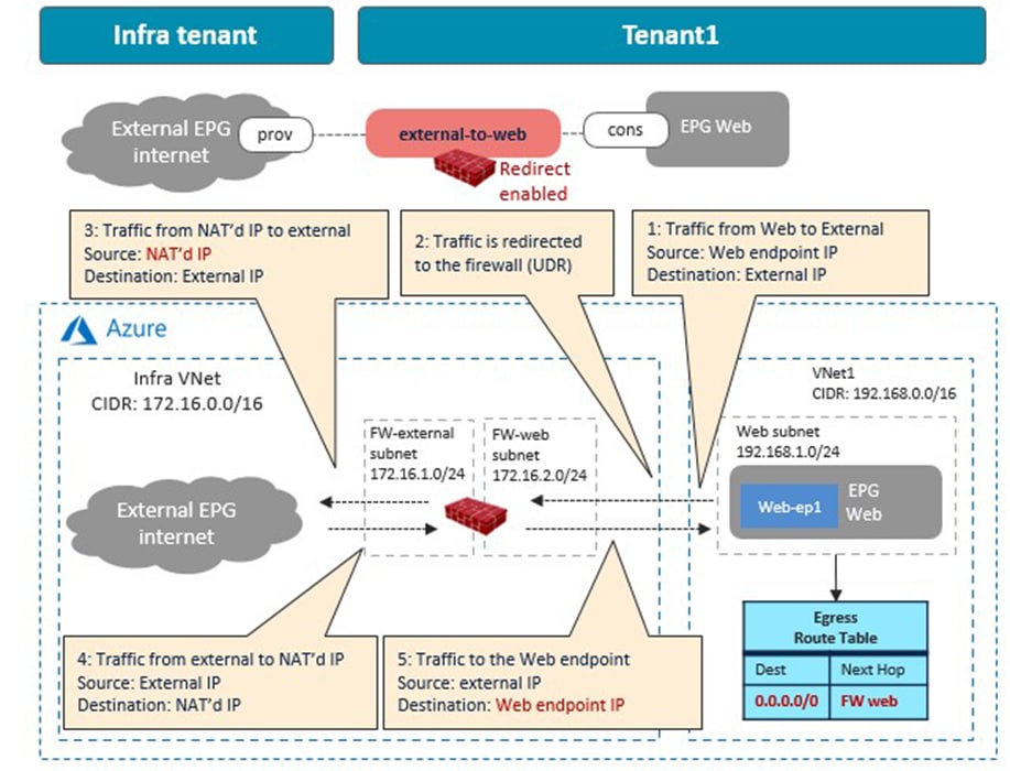
As part of the service graph deployment with the contract, Cisco Cloud Network Controller creates an Egress Route Table to redirect traffic to the firewall for communication between the Web subnet and the external EPG subnet. In this example, the Web subnet (192.168.1.0/24) uses the IP address of the firewall in the FW-Web subnet as the next-hop to reach the external network (0.0.0.0/0). NSGs are also updated accordingly.
In addition to the guidelines provided in the firewall insertion considerations in the previous sub section, this use case has the following guidelines:
· The external EPG and the consumer EPG can be in the same VNet or in different VNets.
· For an external to internal (north to south) traffic direction, redirection is supported if traffic is from non-ACI networks (in an external EPG via ExpressRoute) to cloud endpoints in a Microsoft Azure site. Please see NLB-FW insertion for north-south traffic flow for more detail.
· If there is another cloud EPG that has connectivity to the same external network but doesn’t require redirection, its subnet might need to be in a different CIDR from the subnet for the cloud EPG that requires redirection. Please see Management network consideration for third-party firewalls section for more detail.
Use Case #8-2: East-West Firewall Insertion: Spoke-to-Spoke Traffic Without NAT
The following figures illustrate examples of a design with firewall insertion without NAT. In this example, cloud EPG “Web” is the consumer and cloud EPG “App” is the provider of the contract. The firewall has two interfaces, trust and untrust, in different subnets. Redirection is enabled for both.
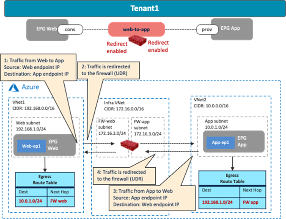
As part of the service graph deployment with the contract, Cisco Cloud Network Controller creates an Egress Route Table for both directions:
· One is to redirect traffic from the Web subnet to the App subnet, then to the firewall IP address in the FW-Web subnet.
· The other is to redirect traffic from the App subnet to the Web subnet, then to the firewall IP address in the FW-App subnet.
NSGs are also updated to permit traffic from the consumer to the provider subnets. The return traffic from the provider to the consumer is then automatically permitted, even though there is no explicit permit rule.
In addition to the guidelines provided in the firewall insertion considerations in the previous sub section, this use case has the following guidelines:
· The consumer and the provider EPGs deployed in the same region cannot be part of the same VNet.
Common Considerations for Service Insertion
This section explains the following common design considerations for service insertion that are applicable to both firewalls and load balancers:
· Management network considerations for third-party appliances
· Service appliances in a subnet in hub VNet (overlay-1)
Management Network Considerations for Third-Party Appliances
This sub-section explains the design considerations for management network for third-party appliances using a third-party firewall as an example.
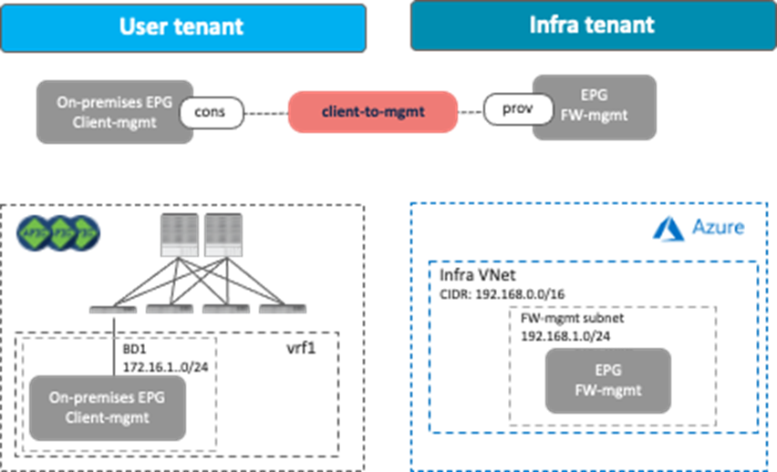
In these examples, the management interface of the firewall is part of the cloud EPG “FW-mgmt” that is the provider of a contract, with an EPG or an external EPG as the consumer. In this case, traffic originated by the firewall and destined to the consumer is not permitted because a contract for a cloud site creates a permit rule for the traffic from the consumer to the provider only. The return traffic from the provider to the consumer is then automatically permitted (even though there is no explicit permit rule) because of the fact that the consumer to the provider traffic was previously observed. Thus, if there is a possibility that the management interface of the service device initiates a communication with another EPG, both EPGs need to be the consumer AND the provider of the contract. Though this consideration is applicable to both examples in this section, the examples use the cloud EPG “FW-mgmt” as the provider EPG.
Management Network Access from On-Premises ACI Fabrics
The following figure provides a design example. To permit traffic between a client in the on-premises ACI fabric and the management interface of the firewall in the cloud, a contract is configured between the EPG “Client-mgmt” and the cloud EPG “FW-mgmt” for the management interface of the firewall. The logical design is similar to Use Case #2: Application stretched across sites (inter-tenant shared service), Though this example uses an inter-VRF contract between EPGs, it can be an intra-VRF contract instead, and a client can be in an on-premises external EPG instead of a regular EPG.
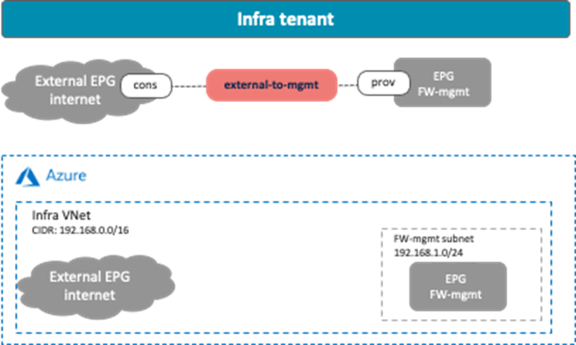
Management Network Access from an External Network
This scenario is applicable to the redirect feature available on Cisco Multi-Cloud Networking solution with Microsoft Azure. The following figure shows a design example. To permit traffic between the external network and the management interface of the firewall, a contract is configured between the external EPG and the cloud EPG “FW-mgmt” for the management interface of the firewall.
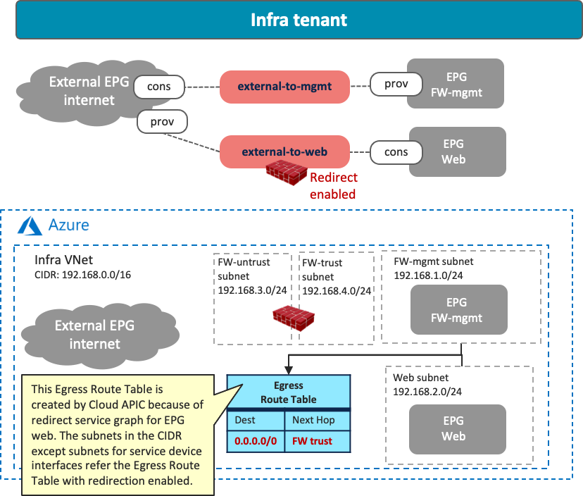
If redirect is enabled for the traffic between the external EPG and a cloud EPG (EPG “Web” in the example below) that is deployed in the same CIDR with the cloud EPG FW-mgmt, the traffic from the FW-mgmt subnet will also be redirected because of the Egress Route Table configured by Cisco Cloud Network Controller for the other cloud EPG contract (the contract “external-to-web” in the example below). As part of a service graph deployment with redirect, Cisco Cloud Network Controller creates the Egress Route Table to redirect traffic to the firewall from all of the subnets in the CIDR, except for the subnets for the service device interfaces, as illustrated below. In this situation, the connectivity from the external network to the cloud EPG FW-mgmt could be lost.
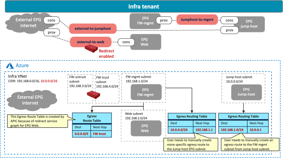
In that case, you must use a jump host in a different CIDR to access the management interface of the firewall in the cloud EPG “FW-mgmt”. The following figure illustrates an example configuration. A cloud EPG “Jump-host” is in the “Jump-subnet” that is in a different CIDR from the cloud EPG “Web”. Because the CIDR is different, the “Jump-host” subnet doesn’t refer to the Egress Route Table with redirect for the firewall insertion. By adding Egress Route Tables and a contract between “FW-mgmt” and “Jump-host” accordingly, the administrator can access a jump-host VM and then access the management interface of the firewall from the jump-host VM.
Service Appliances in a Subnet in Hub VNet (overlay-1)
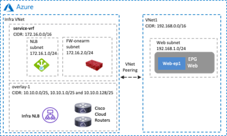
This sub-section explains the scenario of adding CIDRs and subnets in a hub VNet, where these CIDRs and subnets are available to be used for service appliances. This scenario is applicable to Cisco Multi-Cloud Networking solution with Microsoft Azure only.
The overlay-1 VNet in the Azure Portal (also called the “infra VNet” or “hub VNet”) is created by Cisco Cloud Network Controller to deploy the Cisco Cloud Routers and the NLB for Cisco Cloud Router load balancing.
If you need to add service appliances in the hub VNet, you must add a new CIDR and subnets to the hub VNet by using one of the options below.
Prior to Release 25.0(2), Cisco Cloud Network Controller internally created two objects, overlay-1 and overlay-2, in the infra VNet.
· CIDRs in overlay-1 are used to deploy the Cisco Cloud Routers and the NLB for Cisco Cloud Routers load balancing, which are mandatory components in Cisco Multi-Cloud Networking solution.
· CIDRs in overlay-2 can be used to deploy user-defined service appliances. You can add new CIDRs and subnets in overlay-2.
The following figures show an example configuration.

Starting from Release 25.0(2), overlay-2 doesn’t exist unless Cisco Cloud Network Controller was upgraded to 25.0(2) from a previous release. Instead of using overlay-2, you can add new VRFs to the hub VNet, and the new VRFs can be used for new CIDRs and subnets for user-defined service appliances. The following figures show an example configuration.
Since VNet peering must be disabled when adding a new CIDR on overlay-2 or a user-defined VRF in the hub VNet though Cisco Cloud Network Controller, it’s recommended that you create a CIDR for service devices first (adding a new subnet to an existing CIDR doesn’t require disabling VNet peering).
Use Case #9: Multi-Node Services Insertion
This use case is a multi-node services insertion between EPGs using contracts with a service graph. Cisco Multi-Cloud Networking solution supports the combinations of third-party firewalls, cloud native load balancers, and third-party load balancers in the same service graph. For single-node service insertion, please see the Load balancer insertion and Firewall insertion sections.
The key benefit of this use case is to increase high availability and the capacity for firewall inspection by distributing traffic to multiple firewalls.
This section explains various multi-node services insertion use cases, describing traffic flows and associated deployment considerations for each option:
· NLB-FW insertion for east-west traffic flows: Service devices are inserted between the consumer and provider endpoints that are in different Vnets. The traffic flows are distributed to multiple firewalls by the NLB function deployed in front of the firewalls.
· NLB-FW insertion for north-south traffic flows: Service devices are inserted between external networks toward the non-ACI on-premises site and the provider endpoints. The traffic flows are distributed to multiple firewalls by NLB in front of the firewalls.
· NLB-FW-LB insertion: Another load balancer (NLB, ALB, or third-party load balancer) can be added behind the firewalls to distribute traffic to provider endpoints in the cloud platforms.
For a list of other use cases, please see the Deploying Layer 4 to Layer 7 Services section in Cisco Cloud APIC for Azure User Guide.
The following figures illustrate examples of a design with a multi-node service graph.
· The private load balancer is inserted in the contract “web-to-app” between the EPG “Web” and the EPG “App”.
· The public load balancer is inserted in the contract “external-to-web” between an external EPG “internet” and the EPG “web”.
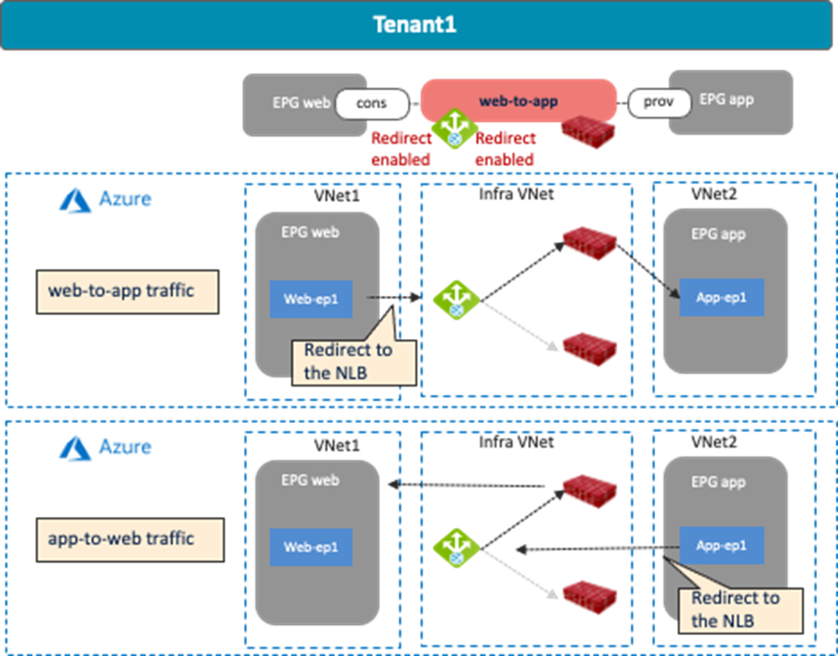
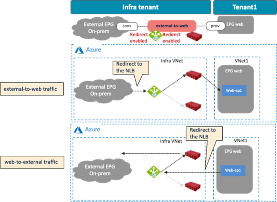
The following figure illustrates the use case of a three-node service insertion that has another load balancer (NLB, ALB, or third-party load balancer) behind the firewalls.
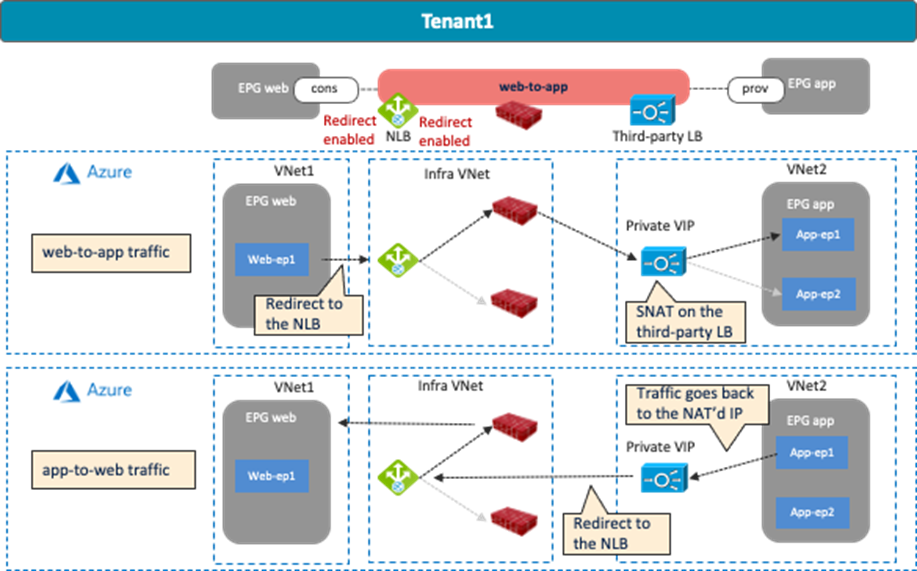
Multi-node service insertion has the following guidelines:
· Service device interfaces must be in a dedicated subnet that must be different from the subnet where the cloud EPG resides.
· For inter-VNet traffic, VNet peering is required.
· The redirect destination (the NLB IP address in this example) must be in the hub VNet (the infra VNet).
· The load balancer interface and its targets must be in the same VNet.
· Inter-site east-west communication is NOT supported at this time. For example:
o When the consumer endpoint is in an AWS site and the provider endpoint is in a Microsoft Azure site.
o When the consumer endpoint is in an ACI on-premises site and the provider endpoint is in a Microsoft Azure site.
· For an external to internal (north to south) traffic direction, redirection is supported if traffic is from non-ACI networks (in an external EPG via ExpressRoute) to cloud endpoints in a Microsoft Azure site.
· In the case of a multi-node service graph, the third-party load balancer interface must use the “subnet-based” interface selector.
Use Case #9-1: NLB-FW Insertion for East-West Traffic Flow
The following figures illustrate an example of a design with an NLB load balancing east-west traffic to multiple firewalls. In this example configuration, the cloud EPG “Web” is the consumer and the cloud EPG “App” is the provider of the contract. The firewall has one interface.
Redirection is enabled for both directions for NLB.
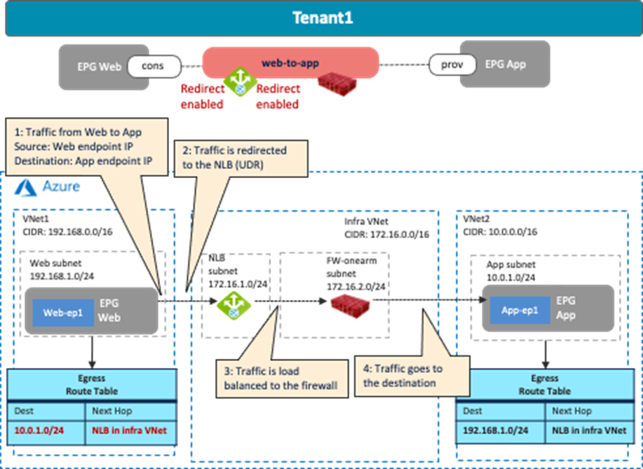
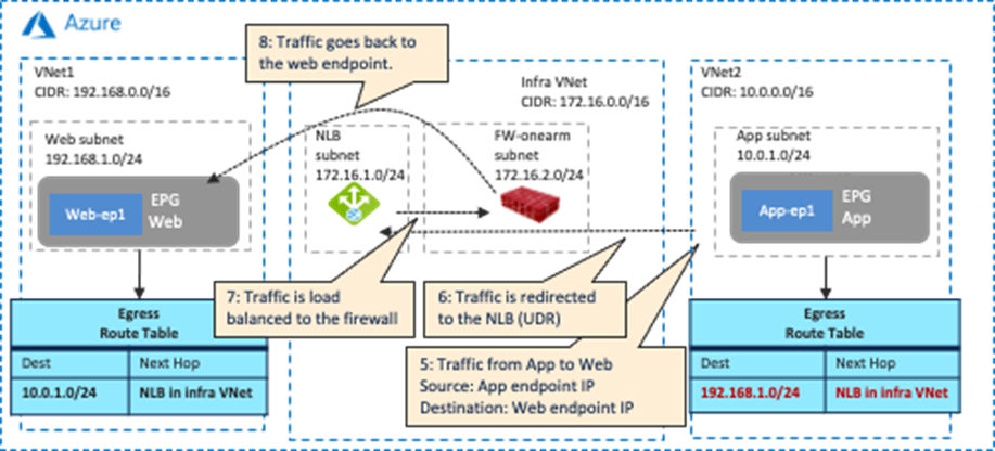
As part of the service graph deployment with the contract, Cisco Cloud Network Controller creates an Egress Route Table for both directions.
· One is to redirect traffic to the NLB IP address for Web subnet to App subnet communication.
· The other is to redirect traffic to the NLB IP address for the App subnet to Web subnet communication.
The NLB ensures that both incoming and return traffic are load balanced to the same firewall. Cisco Cloud Network Controller also updates NSGs and NLB configurations accordingly. For example, Cisco Cloud Network Controller adds an ingress security rule and an egress security rule to the NSG of the firewall, which permits traffic from the consumer subnet to the provider subnet. The return traffic from the provider to the consumer is then automatically permitted, even though there is no explicit permit rule.
In addition to the guidelines provided in the multi-nodes service insertion considerations in the previous sub-section, this use case has the following guidelines:
· The consumer and the provider EPGs, when deployed in the same region, cannot be part of the same VNet.
Use Case #9-2: NLB-FW Insertion for North-South Traffic Flow
The following figures illustrate an example of a design with NLB load balancing north-south traffic to multiple firewalls. In this example configuration, the external EPG “On-Prem” connected to the non-ACI on-premises site is the consumer, and the cloud EPG “Web” is the provider of the contract. The firewall has one interface. Redirection is enabled for both directions for NLB.
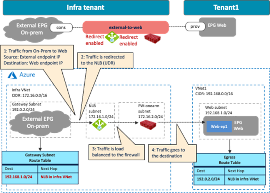
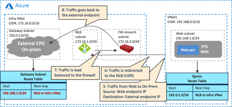
As part of the service graph deployment with the contract, Cisco Cloud Network Controller creates an Egress Route Table for both directions.
· One is to redirect traffic from the External EPG subnet to the Web subnet, then to the NLB IP address.
· The other is to redirect traffic from the Web subnet to the External EPG subnet, then to the NLB IP address.
The NLB ensures that both incoming and return traffic are load balanced to the same firewall. Cisco Cloud Network Controller also updates NSGs and NLB configurations accordingly.
In addition to the guidelines provided in the multi-nodes service insertion considerations in the previous sub-section, this use case has the following guidelines:
· The external EPG must be via Azure ExpressRoute, which indicates that the external EPG represents a non-ACI on-premises network.
· Release 5.1(2) or later is required to enable redirection for the traffic coming from the non-ACI networks (in the external EPG via ExpressRoute) to a cloud endpoint (in the cloud EPG).
· An external EPG that is not via Azure ExpressRoute doesn’t support redirect.
· Though this document mainly covers redirect use cases, you may also choose to deploy ExpressRoute Gateway in the hub VNet without redirect.
· If there are multiple Hub VNets in different Cisco Cloud Network Controller-managed regions within a site (inter-region design), the following design guidelines apply:
o Each region must have an ExpressRoute Gateway in the hub VNet.
o Each ExpressRoute Gateway is connected to the same routing domain and receives the same set of routes from the customer network.
o For a given spoke, the hub VNet in the local region will be the first choice as the transit VNet. If the ExpressRoute Gateway in the local region is not available because of a failure, an alternate region will be selected automatically.
Use Case #9-3: NLB-FW-LB Insertion
The purpose of this use case is to add another load balancer (NLB, ALB, or third-party load balancer) to the use case described in NLB-FW insertion for east-west traffic flow, as shown in the following figures. Though this sub-section uses as an example of adding another load balancer for an east-west traffic flow (Use Case #9-1), it’s also a valid design to add another load balancer for a north-south traffic flow (Use Case #9-2).
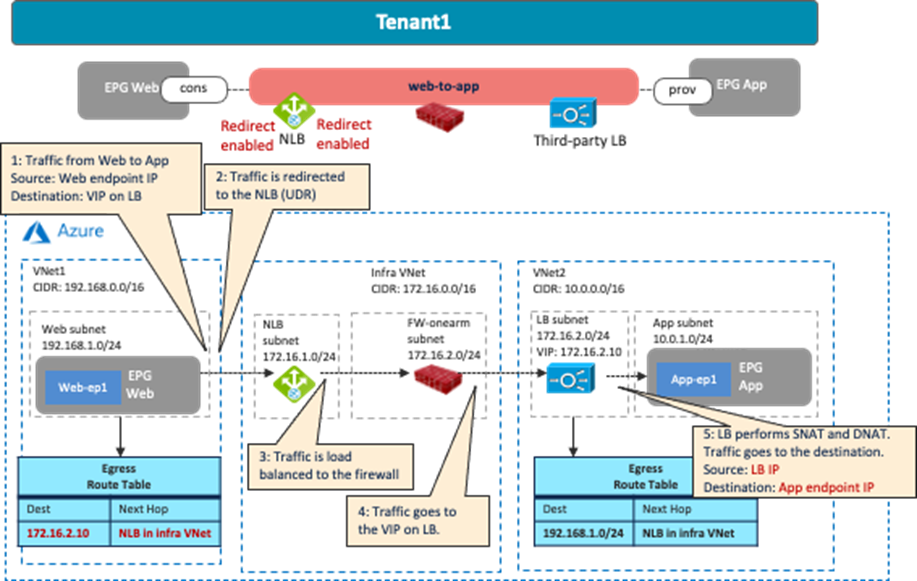
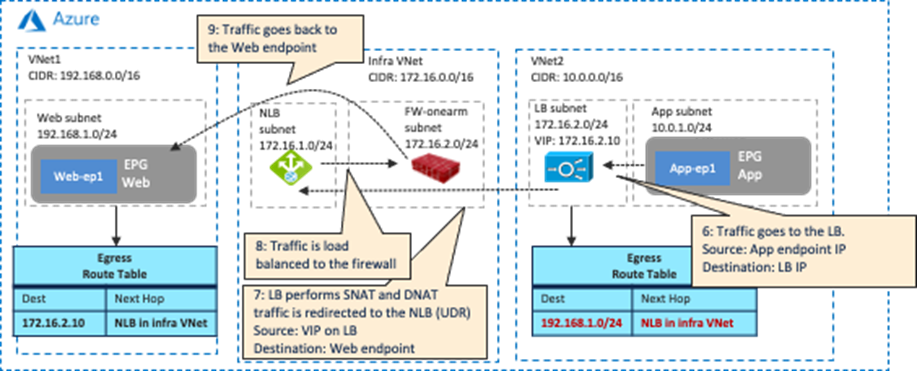
As part of the service graph deployment with the contract, Cisco Cloud Network Controller creates an Egress Route Table for both directions.
· One is to redirect the traffic from the Web subnet and the VIP of the third-party load balancer to the NLB IP address.
· The other is to redirect the traffic from the LB subnet and the Web subnet to the NLB IP address.
The NLB ensures that both incoming and return traffic are load balanced to the same firewall. Cisco Cloud Network Controller also updates the NSGs and NLB configurations accordingly. You must configure the third-party load balancer accordingly as the Cisco Cloud Network Controller does not make those configurations.
In addition to the guidelines provided in the multi-nodes service insertion considerations in the previous sub-section, this use case has the following guidelines:
· The consumer and the provider EPGs cannot be in the same VNet if they are in the same region.
Use Case #10: Cloud Native Service Integration on Microsoft Azure
At this time, this feature is supported on Cisco Multi-Cloud Networking solution with Microsoft Azure only. Cisco Cloud Network Controller introduces a new type of EPG called Cloud Service EPG. Cloud Service EPG is a collection of service units based on configured selectors. As an example, a cloud Storage Service EPG may be comprised of all storage units (containers or blobs in Microsoft Azure) that have been tagged with a specific key and value pair. The Cloud Service EPG also indicates the type of deployment model, such as a Platform as a Service or a Software as a Service.
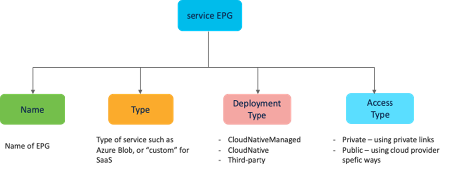
The properties of a Cloud Service EPG are as follows:
· Name: Name of the EPG
· Service Type: Type of the service this EPG represents. For example: Azure Storage, AKS, Databricks, etc. The Service Type will be “custom” for third -party services (SaaS).
· Deployment Type: Services are differentiated based on their deployment models. This field indicates if this is a Cloud Native or a SaaS service, and if it is hosted in the customer VNet or in Azure VNets. In brief, this attribute indicates how and where the service is deployed. The available deployment types are as follows:
o Cloud Native: Cloud native service hosted in Microsoft Azure’s own VNets (not a VNet created by Cisco Cloud Network Controller).
o Cloud Native Managed: A Cloud native service hosted in the customer VNet (a VNet created by Cisco Cloud Network Controller).
o Third-Party: A third-party (not Microsoft Azure) service providing services through the marketplace. Access to this service is provided through the private links feature.
· Access Type: Types of accessibility to the service:
o Public: The service can be accessed using the public IP addresses assigned to it. Access to the public IP address range of a particular service is achieved using the Azure "Service Tags" in the NSG rules.
o Private: The service can be accessed using the private IP addresses assigned to it. This assignment is done through the creation of private endpoints when the deployment is set to Cloud Native. In the case of a Cloud Native Managed deployment, the private IP is assigned by the service from the subnet IP space.
For more information about Azure service tags, please refer to: https://docs.microsoft.com/en-us/azure/virtual-network/service-tags-overview
Supported Cloud Service EPG selectors depend on the Deployment Type. For example, in the case of Cloud Native Managed, where cloud services are deployed on the customer’s VNet (a VNet created by Cisco Cloud Network Controller), it is possible to use the following selectors: tags, region, service name, and subnet IP address in which the services are deployed. Once a Cloud Service EPG is created, Cisco Cloud Network Controller automatically creates private endpoints and private links. A contract can be applied to control access from the client machine to the service.
The following figure illustrates an example where a service is grouped into a Cloud Service EPG. Cisco Cloud Network Controller helps to control communication from an EPG to a Cloud Service EPG by programming proper NSG rules. For example, you can deploy an AKS cluster in a VNet created by Cisco Cloud Network Controller, and only traffic from the Internet to reach the AKS service on port TCP 80 is allowed. This port is configured in the filter rule on the contract that is applied between the Internet external EPG and the AKS Cloud Service EPG “AzureEKS”. Cloud administrators can also configure another contract with different rules to control communication from an EPG (for example, Client-EPG) to the AKS Cloud Service EPG “AzureEKS”. The EPG can be in the same VNet or in a different VNet as the Cloud Service EPG.
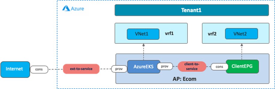
Use Case #11: Brownfield Import on Microsoft Azure and AWS
This use case is used when you have existing public cloud resources that need to connect to a Cisco Multi-Cloud Networking infrastructure. Prior to Release 5.2(1), the Cisco Multi-Cloud Networking solution only supports greenfield environments where Cisco Cloud Network Controller creates Resource Groups, VPCs/VNets, CIDRs, subnets, etc. from scratch, which means existing brownfield environments (where Resource Groups, VPCs/VNETs, etc. are already created by the users without Cisco Cloud Network Controller) cannot coexist in Cisco Cloud Network Controller-managed resources. Starting from Release 5.2 for Microsoft Azure and Release 25.0(2) for AWS, capabilities for co-existence with brownfield environments with the “Read-only” option are supported. Starting from Release 25.0(4) for Microsoft Azure and AWS, “Routing & Security” and “Routing-only” options are also supported.
Cisco Cloud Network Controller supports the import of the existing brownfield VPCs/VNets and automates network and security policy connectivity from Cisco Cloud Network Controller-managed Resource Groups, including VPCs/VNets and SGs/NSGs. Depending on the access policy configuration, the objects that Cisco Cloud Network Controller manages in the brownfield VPC/VNet are different. The access policy is used to define a privilege in the Cisco Cloud Network Controller for each resource, such as tenant, VPC/VNet and subnet.
The types of access policies are as follows:
· Read Only: Cisco Cloud Network Controller doesn’t configure or provision anything in existing brownfield objects such as tenants, VPC/VNet and subnet. The assumption is that security and routing in existing brownfield Resource Groups will still be owned by the user. This option was called “Unmanaged” prior to Release 25.0(4).
· Routing Only: Cisco Cloud Network Controller controls the routing configuration in existing brownfield Resource Groups. The assumption is that security in existing brownfield Resource Groups will still be owned by the user.
· Routing and Security: Cisco Cloud Network Controller controls both routing and security configurations in existing brownfield Resource Groups. This option is the default access policy starting from Release 25.0(4).
At this time, the brownfield import process is done on Cisco Cloud Network Controller itself; NDO does not support brownfield import yet. Once the supported resources are imported to Cisco Cloud Network Controller, NDO can then import those resources from Cisco Cloud Network Controller. From an NDO perspective, after the resources are imported to the NDO template, there is no difference between brownfield and greenfield resources. The next sub-section covers high-level procedures to do a brownfield import for Microsoft Azure and AWS separately along with their specific considerations.
Brownfield Import for Microsoft Azure
Brownfield resources can be in the same or in different Azure subscriptions as greenfield resources. Brownfield resources can even be in a separate Azure subscription that is in a different Active Directory than the greenfield subscription. If the brownfield resources are in a different Azure subscription, Cisco Cloud Network Controller first needs to create a new tenant to represent the brownfield Azure subscription.
Read Only Access Policy (Unmanaged)
Brownfield VNets with a “Read Only” access policy were previously called Unmanaged Virtual Networks, which is why the button title on the Cisco Cloud Network Controller GUI shows “Unmanaged Virtual Network” or “Import Brownfield Virtual Network”, depending on the release.
For instance, to import brownfield VNets, from the Intent Button, you can choose the Import Brownfield Virtual Network option under the Workflows section.

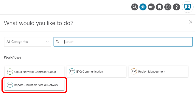

After the brownfield import, Cisco Cloud Network Controller automatically initiates a VNet peering request to the brownfield (unmanaged) VNets from the infra VNet (overlay-1 VNet). It is the responsibility of the end user to initiate a peering session back to the infra VNet from the brownfield VNets to complete the VNet peering session.
As only the subnet-based selector EPG is supported, the Cisco Cloud Network Controller administrator needs to create subnet-based selector EPGs to represent endpoints on brownfield VNets.
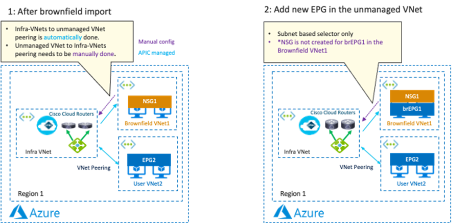
Cisco Cloud Network Controller automates the Cisco Cloud Router routing configuration to route traffic between the greenfield VNets and the brownfield VNets. Once a contract is applied between the greenfield EPGs and the brownfield EPGs, Cisco Cloud Network Controller automates NSG rules at the greenfield side, and automatically adds a UDR route entry on the greenfield VNets Route Table. It is the end user’s responsibility to configure or edit the UDR route table entry on the brownfield VNets and configure or edit the NSG rule to allow proper communication between the greenfield EPG and the brownfield EPG.
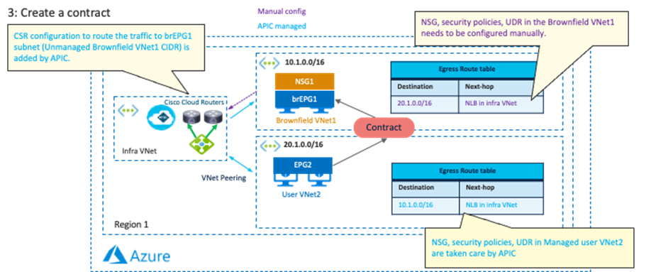
A brownfield import with a “Read Only” access policy has the following guidelines:
· There are several things that Cisco Cloud Network Controller won’t do on these Brownfield Resource Groups. It is the responsibility of the brownfield VNet owner to create all of these policies and apply them. Cisco Cloud Network Controller will not create the Route Tables with the UDRs pointing to the Infra NLB based on the contracts with the Greenfield EPGs. Cisco Cloud Network Controller will not create any NSGs and ASGs in these Brownfield Resource Groups. There is no endpoint discovery done for the endpoints in these Brownfield Resource Groups. Cloud EPGs associated with the brownfield VNet should have subnet-based endpoint selectors (tag-based EPGs will not be applicable on a brownfield VNet).
· All configurations within the brownfield VNet needs to be managed by the user. Cisco Cloud Network Controller will only automate connectivity from greenfield into brownfield VNets. A brownfield VNet can be present anywhere (for example, in the same subscription or in different subscriptions in the same Active Directory domain, or in different Active Directory domains altogether). You should also have a service principal associated with this unmanaged subscription that has the read permissions on various resources.
· Service redirection between brownfield VNets and greenfield VNets is not officially supported yet.
Routing & Security and Routing Only Access Policy
These options are available after Release 25.0(4).
In this example, we assume that the existing brownfield “brown1” route table has 10.2.2.0/24 (another brownfield VNet “brown2”) via existing brownfield VNet peering, and there is no communication available yet between the brownfield VNet “brown1” and the greenfield VNet.
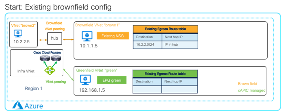
After importing the brownfield VNet “brown1” and choosing the subnets to import, Cisco Cloud Network Controller automatically initiates a VNet peering request between the brownfield VNet “brown1” and the infra VNet (overlay-1 VNet) and creates an egress route table for the brownfield VNet “brown1” by copying the existing egress route table as shown in the figure below. At this point, though the chosen subnets start using the newly-created egress route table managed by Cloud Network Controller, VMs in the brownfield VNet “brown1” should still have connectivity to other brownfield VNets because the next-hop IP address is still the IP address via the existing brownfield VNet peering.
After creating an EPG in the “brown1” VNet and adding a contract with a greenfield EPG (in this example, it’s a contract between EPG “brown1” and EPG “green”), egress route tables on both VNets are updated accordingly as shown in the figure below. This is done so that the VMs in the brownfield VNet “brown1” can reach the subnet in the greenfield VNet and also the subnet in the brownfield VNet “brown2”.
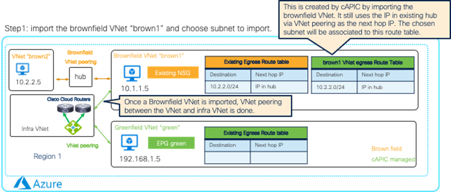
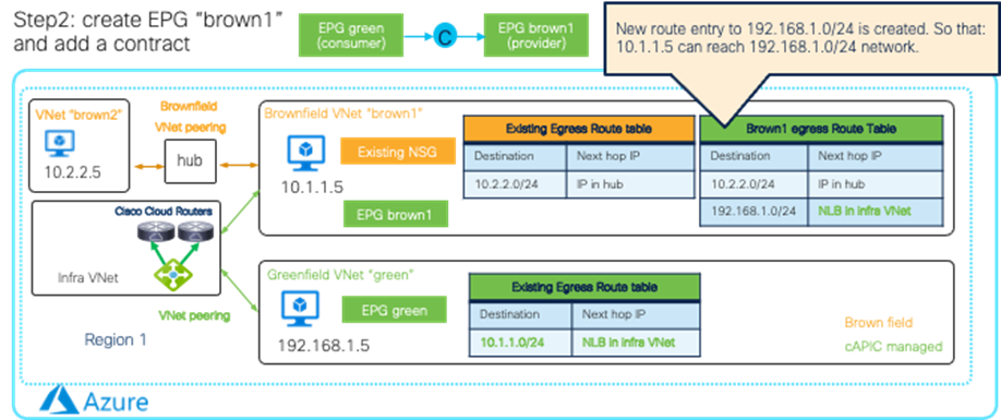
With the “Routing & Security” access policy, brownfield endpoints (10.1.1.5 in this example) will move to the newly-created EPG “brown1” based on the EPG selector, and NSGs are updated by Cisco Cloud Network Controller based on the contract. This is done so that communication between endpoints in the EPG “brown1” and endpoints in the EPG “green” are permitted. In order to maintain communication between endpoints in the EPG “brown1” and endpoints in the “brown2” VNet, we need to import the “brown2” VNet and add another contract between the EPG “brown1” and another EPG in the “brown2” VNet. The egress route “10.2.2.0/24 via IP in hub” will be replaced with “10.2.2.0/24 via NLB in infra VNet”.
With the “Routing Only” access policy, Cisco Cloud Network Controller doesn’t manage NSGs in the brownfield VNet. It is the end user’s responsibility to configure or edit the NSG rule in the brownfield VNet to allow proper communication between the greenfield EPG and the brownfield EPG.
A brownfield import with “Routing & Security” and “Routing Only” options for Microsoft Azure has the following guidelines:
· Service redirection between brownfield VNets and greenfield VNets is supported with the “Routing & Security” option.
· It’s recommended to add tags for EPG classification before importing a brownfield VNet so that endpoints in the brownfield VNet will be classified to the EPGs, which gets the routing and security configuration programmed by Cisco Cloud Network Controller during the brownfield VNet import.
For a more detailed procedure, see:
Brownfield resources can be in the same or in different AWS accounts as the greenfield resources. If brownfield resources are in a different AWS account, Cisco Cloud Network Controller first needs to create a new tenant to represent the AWS account.
Read Only Access Policy (Unmanaged)
Brownfield VPCs with a “Read Only” access policy were previously called Unmanaged VPCs, which is why the button title on the Cisco Cloud Network Controller GUI is “Unmanaged VPC” or “Import Brownfield Virtual Network”, depending on the release.
For instance, to import brownfield VPCs, from the Intent Button, choose the Import Brownfield VPC option under the Workflows section.
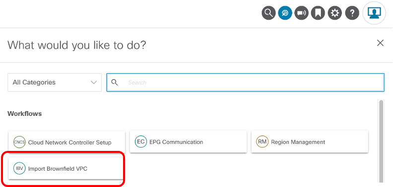

After the brownfield import, you must manually create a brownfield VPC attachment to the greenfield TGW (the TGW that was created by Cisco Cloud Network Controller).
As only the subnet-based selector EPG is supported, the Cisco Cloud Network Controller administrator needs to create subnet-based selector EPGs to represent endpoints on the brownfield VPCs.
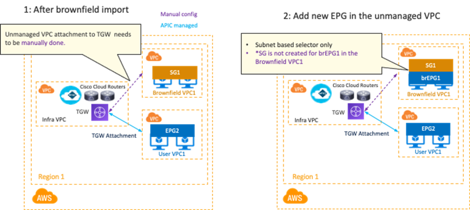
Once a contract is applied between greenfield EPGs and brownfield EPGs, Cisco Cloud Network Controller automates SG rules at the greenfield side. Cisco Cloud Network Controller also automatically adds a route entry on the greenfield VPC Route Table. It is the end user’s responsibility to configure or edit the VPC route table on the brownfield VPCs and configure or edit SG rules to allow proper communication between the greenfield EPG and the brownfield EPG.
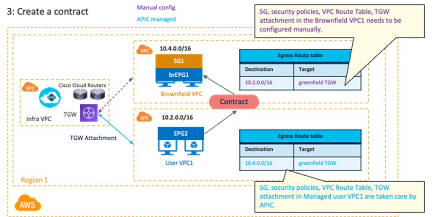
A brownfield import with a “Read Only” access policy has the following guidelines:
· Even though you can selectively import all or a particular set of CIDRs under the brownfield VPC, you cannot import a brownfield VPC without its primary CIDR. Importing the primary CIDR is mandatory when importing a brownfield VPC.
· For greenfield deployment, Cisco Cloud Network Controller still automate configurations such as the TGW, the TGW route tables, and the TGW attachment between the greenfield VPC and the greenfield TGW (the Cisco Cloud Network Controller-managed TGW). Cisco Cloud Network Controller does not configure the TGW attachment for the brownfield VPCs. You must manually configure the TGW attachment from the brownfield VPCs to the greenfield TGW.
· Cisco Cloud Network Controller programs the security group rules for the greenfield VPC to allow inbound and outbound traffic to and from the brownfield VPCs. Cisco Cloud Network Controller does not program the security group rules in the brownfield VPC.
· Cisco Cloud Network Controller does not program any route tables or routes in the brownfield VPC. For the brownfield VPC to communicate with the greenfield VPC, you must manually make the following configurations:
o Create the contract between the greenfield and brownfield EPGs.
o Create the transit gateway VPC attachment with the greenfield TGW in the infra VPC.
o Create or edit the route table for the brownfield VPC and the subnets.
o Add the routes where the destinations are the greenfield CIDRs and the next hop is the greenfield TGW VPC attachment.
· Cloud EPGs associated with the brownfield VPC should have subnet-based endpoint selectors (tag-based EPGs will not be applicable on a brownfield VPC).
Routing & Security and Routing Only access policy
These options are available after Release 25.0(4).
In this example, we assume that the existing brownfield “brown1” route table has 10.2.2.0/24 (another brownfield VPC “brown2”) via the existing TGW, and that there is no communication available yet between the brownfield VPC brown1 and the greenfield VPC.
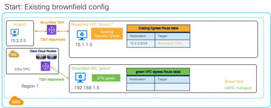
After importing the brownfield VPC “brown1” and choosing the subnets to import, Cisco Cloud Network Controller automatically configures a TGW attachment for the brownfield VNet “brown1” toward the greenfield TGW managed by Cloud Network Controller and creates an egress route table for the brownfield VPC “brown1” by copying the existing egress route table as shown in the figure below. At this point, though the chosen subnets start using the newly-created egress route table managed by Cisco Cloud Network Controller, VMs in the brownfield VPC “brown1” should still have connectivity to the other brownfield VNet because the brownfield TGW is still the target.
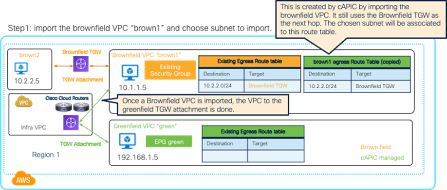
After creating an EPG in the “brown1” VPC and adding a contract with a greenfield EPG (in this example, it’s a contract between EPG “brown1” and EPG “green”), egress route tables on both VPCs are updated accordingly as shown in the figure below. This is done so that the VMs in the brownfield VPC “brown1” can reach the subnet in the greenfield VPC, and also the subnet in the brownfield VPC “brown2”.
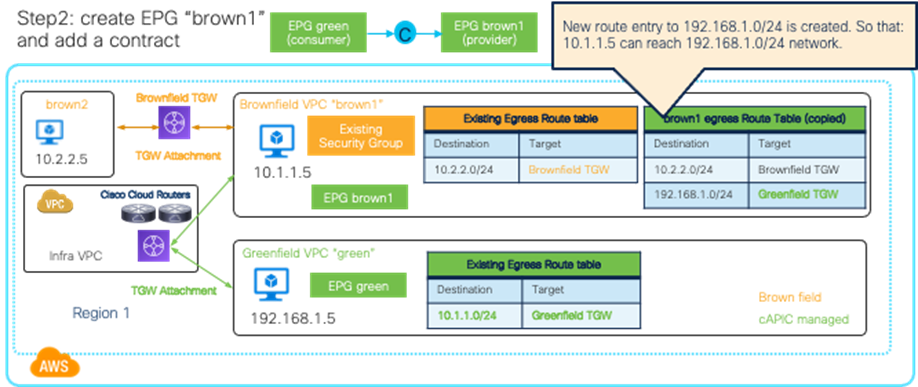
With the “Routing & Security” access policy, brownfield endpoints (10.1.1.5 in this example) will move to the newly-created EPG “brown1” based on the EPG selector, and the security group rules are updated by Cisco Cloud Network Controller based on the contract. This is done so that communication between endpoints in the EPG “brown1” and endpoints in the EPG “green” are permitted. In order to maintain communication between endpoints in the EPG “brown1” and endpoints in the “brown2” VPC, we need to import the “brown2” VPC and add another contract between the EPG “brown1” and another EPG in the brown2” VPC. The egress route “10.2.2.0/24 via the Brownfield TGW” will be replaced with “10.2.2.0/24 via Greenfield TGW”.
With the “Routing Only” access policy, Cisco Cloud Network Controller doesn’t manage security group rules in the brownfield VPC. It is the end user’s responsibility to configure or edit the security groups in the brownfield VPC to allow proper communication between the greenfield EPG and the brownfield EPG.
A brownfield import with “Routing & Security” and “Routing Only” options for AWS has the following guidelines:
· It’s recommended to add tags for EPG classification before importing a brownfield VPC so that endpoints in the brownfield VPC will be classified to the EPGs, which gets the routing and security configuration programmed by Cisco Cloud Network Controller during the brownfield VPC import.
Use Case #12: Workload Mobility for Disaster Recovery (DR)
Workloads for critical applications are supposed to be distributed across multiple availability zones and regions, which are load balanced by cloud native load balancers or third-party load balancers.
Although a typical assumption is that there are no overlapping IP ranges across VPCs if they are peered or connected via other network components, this section explains a DR use case example where standby VM instances use the same IP range as the VPC for primary VM instances. An advantage of this use case is that there is no need to reassign the IP addresses during a switchover from a primary VPC to a secondary VPC in a different region.
Although the example in this section explains Primary/Secondary VPC switchover within an AWS site, it should also be applicable to a Microsoft Azure site. It’s not applicable to a GCP site as of Cisco Cloud Network Controller Release 25.1(1).
Primary and Secondary VPCs Design
The figure below illustrates an example of Primary and Secondary VPCs design. The important assumption is that the Primary VPC was created through Cisco Cloud Network Controller and NDO, and the Secondary VPC was created outside of Cisco Cloud Network Controller using the same IP prefixes as the Primary VPC. During the switchover, the Secondary VPC will be imported to the Cisco Cloud Network Controller, and the Cisco Cloud Network Controller automates the network and security configuration migration for the Secondary VPC.
In this example, the Primary VPC is in the us-east-2 region and the Secondary VPC is in the us-west-2 region. When the Primary VPC is up, VM1 in the us-east1 region can talk to VM2 in the us-east-2 region through the TGW managed by Cisco Cloud Network Controller.
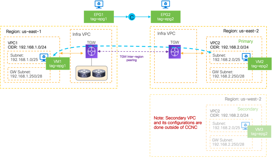
Following are the key design considerations:
· VM instances are deployed in the Secondary VPC using the same IP prefixes as the Primary VPC. In this example, the VM instances in the Secondary VPC even use the same IP addresses as the VM instances in the Primary VPC, which might be useful if an IP address is used within the application instead of DNS. In this example, VM2 and VM3 use the same IP address.
· The VM instances in the Secondary VPC use the same tags as the VM instances in the Primary VPC. This is to ensure that the same security configuration will be applied to the VM instances in the Secondary VPC after the switchover. In this example, VM2 and VM3 use the same tag.
· The Secondary VPC is not connected to the TGW before switchover, which means that the VM instances in the Secondary VPC are not actually used to serve the application.
Switchover after a Failure (DR Scenario)
This section explains a workflow to enable a connectivity to the Secondary VPC if a major failure occurs and the decision is made to switchover the application tier to the Secondary VPC from the Primary VPC.
An example workflow for the switchover is as follows:
1. On the Cisco Cloud Network Controller: Delete the Cloud Context Profile for the Primary VPC (VRF). Otherwise, traffic destined to the subnet (192.168.2.0/24 in this example) could still be forwarded to the Primary VPC because the VM2 in the Primary VPC and its subnet could be still active.
2. On the Cisco Cloud Network Controller: Import the Secondary VPC into the same VRF using Brownfield Import with the “Routing & Security” access policy.
Note: Since the Cloud Context Profile was deleted in step 1, the new Cloud Context Profile is created and associated to the Secondary VPC, whereas the EPGs and the associated contracts are still there in the tenant configuration. It means the following configurations for the Secondary VPC will be automatically done based on the EPGs and contracts configuration, which should be equivalent to what the Primary VPC had:
· TGW deployment in the region where Secondary VPC resides
· TGW configurations such as inter-region peerings and TGW attachments
· Route Tables on the Secondary VPC
· Security Groups for the EPG in the Secondary VPC (EPG2 in this example)
3. (Optional) If NDO is used to manage the tenant configuration for the Primary VPC (VPC1 in this example), the newly-imported Secondary VPC (VPC2 in this example) information needs to be synced from the Cisco Cloud Network Controller to the NDO.
On the NDO: At the template used to manage the tenant configuration, import the VRF created in step 2 (in the example use VRF-2) from the Cisco Cloud Network Controller. This will replace the old Primary VPC region information with the Secondary VPC region information in the NDO.
4. (Optional) If you want to switch back to the Primary VPC later, on the Cisco Cloud Network Controller, delete the Cloud Context Profile, create a new Cloud Context Profile, and import the Primary VPC, similar to step 1 and 2. If NDO is used, import the VRF from the Cisco Cloud Network Controller back to NDO, similar to step 3.
5. (Optional after step 4) If you decide to perform a switchover from the Primary VPC to the Secondary VPC again, delete the tags on the Secondary VPC in AWS; the tags were added by the Cisco Cloud Network Controller during the Brownfield import in step 2. Otherwise, the brownfield import for the Secondary VPC cannot be performed again because Cisco Cloud Network Controller doesn’t identify a VPC for the brownfield import if those tags exist on the VPC.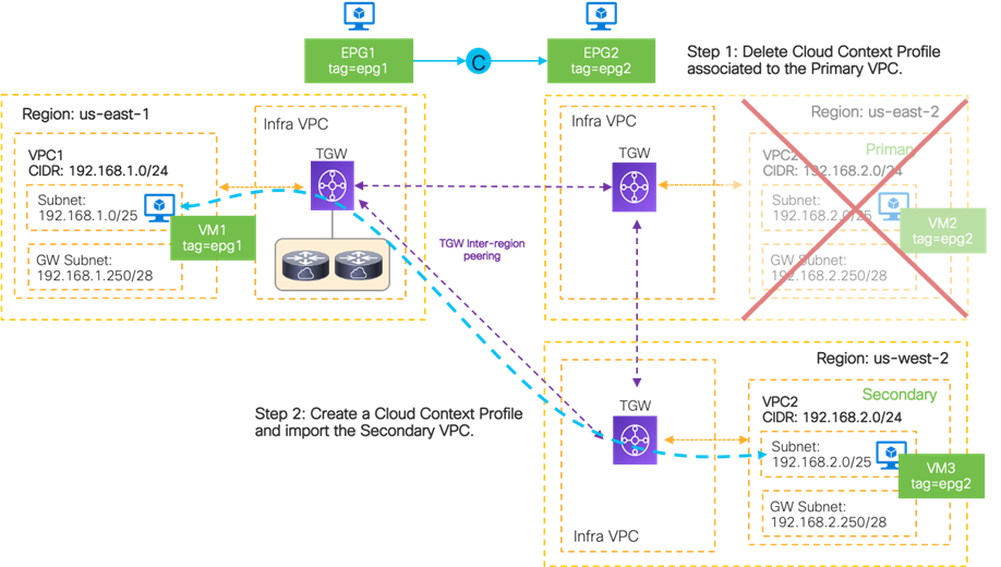
This use case has the following considerations:
· This scenario is applicable to a cloud site if the brownfield import with “Routing & Security” access policy is supported. If it’s a “Routing Only” access policy, the security configuration is not automatically updated, whereas the routing configuration is still automatically updated in step 2 above.
· This is for a DR use case, which is intended to be used if a major failure happens. It could take 5-10 minutes or more for the convergence after the switchover, depending on the amount of configuration updates required.
· You should configure and update the apps or VM instances running on the Secondary VPC accordingly to be able to serve the applications after the switchover.
· The Secondary VPC can be in the same or in a different cloud site. If the Secondary VPC (or VNet in the case of a Microsoft Azure site) is in a different cloud site, NDO is required to import the Secondary VPC/VNet from the Cisco Cloud Networking Controller for the cloud site to establish the inter-site connectivity.
Use Case #13: Firewall Redundancy with AWS GWLB (Gateway Load Balancer)
This section explains the following third-party firewall insertion use cases using AWS Gateway Load Balancer (GWLB):
· North-south traffic flow between the Internet and a VM instance in a cloud site
· East-west traffic flow between VM instances in different VPCs
· East-west traffic flow between a greenfield VPC and a brownfield VPC
AWS GWLB is a service that makes it easy and cost-effective to deploy, scale and manage the availability of third-party appliances such as firewalls, Intrusion Prevention Systems (IPS) and Deep Packet Inspection (DPI) systems in the cloud.
The figure below illustrates an example. VPC1 is for the VM instances, and Service-VPC is for the firewall and the GWLB. The following items are the key components in this example.
1. Each third-party firewall has one interface for traffic forwarding and one management interface. The firewalls interfaces are in a subnet (or multiple subnets) in Service-VPC. The firewalls don’t necessarily have to be clustered.
· The interface for traffic forwarding is in the private subnet “FW-data”.
· The management interface is in the private subnet “FW-mgmt”. An instance in the public subnet “FW-JumpHost” is used to access the FW management interface.
2. In this example, VM instances in the public subnet “App1-data” and “App2-data” will be used in the explanations for north-south and east-west traffic flows through the firewalls.
· An instance in the public subnet “JumpHost” is used to access the VM instance console.
3. The GWLB in the private subnet “GWLB” has a target group that is associated with the firewalls.
4. Geneve encapsulation is used between the GWLB and the firewalls. The firewalls must support Geneve encapsulations.
5. The GWLB VPC endpoint service in the private subnet “GWLB” is created on the GWLB in Service-VPC.
6. The GWLB endpoint (GWLBe) in the public subnet “GWLBe” is associated to the GWLB VPC endpoint service. This is the AWS Private Link from the GWLBe to the GWLB.
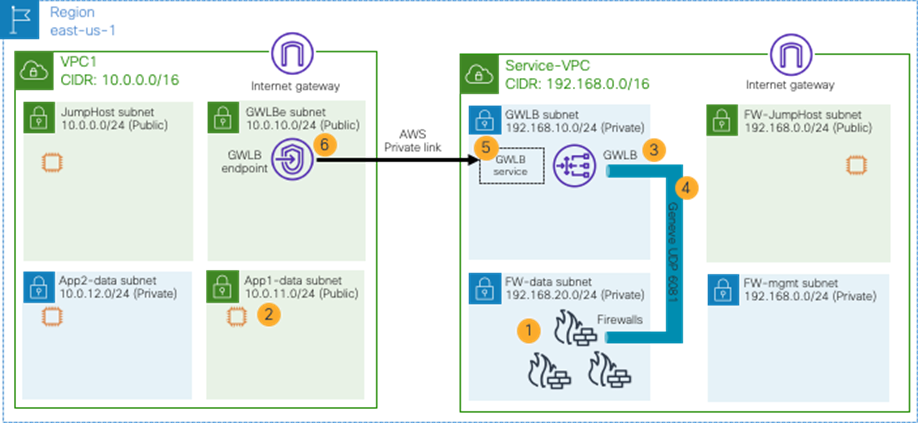
This use case has the following considerations:
· This scenario is applicable to a cloud site with AWS.
· Although this example doesn’t use AWS TGW, a firewall insertion design with GWLB can be used with AWS TGW. If traffic is across availability zones, appliance mode needs to be enabled on the TGW to use the same virtual appliance. Please see AWS Transit Gateway document for details.
· The firewalls must support Geneve encapsulations.
· The firewalls and the GWLB must be in a different VPC than the VM instances.
· The firewalls and the GWLB must be in the same region as the VM instances.
· The GWLB and the GWLB endpoint must be in the same availability zone.
· Sticky session must be enabled on the AWS target groups because firewalls in a cloud site don’t support active/standby or a clustering feature in general.
· Because Cisco Cloud Network Controller currently doesn’t support network and security configuration automation with AWS GWLB, the VPCs for the VM instances and firewalls (VPC1 and Service-VPC in this example) and custom egress routes need to be configured accordingly outside of Cisco Cloud Network Controller. You may import the VPCs to Cisco Cloud Network Controller by using the “Read-only” access policy. Please see the sub-section for detail.
Each subnet in the VPCs needs to be configured accordingly to insert a firewall in the traffic path. The figure below illustrates egress route table configuration examples.
Note that third-party appliances typically have a management interface in addition to interfaces for traffic inspection, though this section mainly focuses on networks for traffic inspection. The example below includes subnets used for management as well.
Following are the subnets in Service-VPC:
· “FW-JumpHost” subnet that is used for a VM instance to access the firewall management interfaces, which has the following egress routes:
o 192.168.0.0/16 as the local subnet (CIDR)
o 0.0.0.0/0 via the Internet Gateway that is used to access the Internet
· “GWLB”, “FW-data” and “FW-mgmt” subnets, which have the following egress route:
o 192.168.0.0/16 as the local subnet (CIDR)
Following are the subnets in VPC1:
· “JumpHost” and “GWLBe” subnets, which have the following egress routes:
o 10.0.0.0/16 as the local subnet (CIDR)
o 0.0.0.0/0 via the Internet Gateway that is used to access the Internet
· "App1-data” subnet, which has the following egress routes:
o 10.0.0.0/16 as the local subnet (CIDR)
o 0.0.0.0/0 via the VPC endpoint (the GWLBe, or VPC-ep-id in the figure below) , which is used to access the Internet and VM instances in “App2-data” subnet through a firewall
· App2-data” subnet, which has the following egress routes:
o 10.0.0.0/16 as the local subnet (CIDR)
o 10.0.11.0/24 via the VPC endpoint (VPC-ep-id in the figure below), which is used to access VM instances in “App1-data” subnet through a firewall
· The IGW in VPC1, which has the following ingress routes:
o 10.0.0.0/16 as the local subnet (CIDR)
o 10.0.11.0/24 via the VPC endpoint (VPC-ep-id in the figure below), which is used to access VM instances in “App1-data” subnet through a firewall
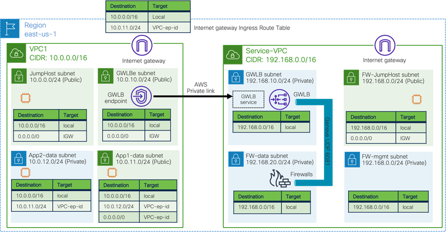
North-South Traffic Flow between the Internet and a VM Instance in a Cloud Site
The figure below illustrates traffic flow from the Internet to a VM instance in a cloud site. In this example, the destination IP address is in the 10.0.11.0/24 subnet.
1. Traffic from the Internet to the “App1-data” subnet is forwarded to the GWLBe based on the IGW ingress route table (10.0.11.0/24 via VPC-ep-id in this example).
2. Traffic is forwarded to the GWLB on the Service-VPC through the AWS Private Link.
3. The GWLB forwards the traffic to one of the firewalls using Geneve encapsulation.
4. The firewall applies its security policy on the traffic and sends the traffic back to the GWLB using Geneve encapsulation.
5. The GWLB sends the traffic back to the GWLBe through the AWS Private Link.
6. The GWLBe subnet has a local route for the destination subnet (10.0.0.0/16 in this example). Thus, the traffic is forwarded to the destination.
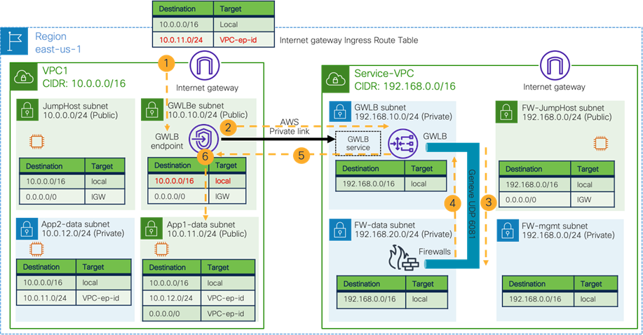
The figure below illustrates the return traffic from the VM instance to the Internet.
7. Traffic from the VM instance to the external subnet is forwarded to the GWLBe based on the egress route table (0.0.0.0/0 via VPC-ep-id in this example).
8. Traffic is forwarded to the GWLB on the Service-VPC through the AWS Private Link.
9. The GWLB forwards the traffic to the same firewalls using Geneve encapsulation. This is because Session Stickiness is enabled on the target-group associated with the firewalls.
10. The firewall applies its security policy on the traffic and sends the traffic back to the GWLB using Geneve encapsulation.
11. The GWLB sends the traffic back to the GWLBe through the AWS Private Link.
12. The GWLBe subnet has the default route for the Internet (0.0.0.0/0 via IGW). Thus, the traffic is forwarded to the destination.

East-West Traffic Flow between VM Instances in Different VPCs
The figures below illustrate traffic flow between VM instances in different VPCs. Traffic from the 10.0.11.0/24 subnet to 10.0.12.0/24 is forwarded to the GWLB endpoint based on the egress route table of the “App1-data” subnet.
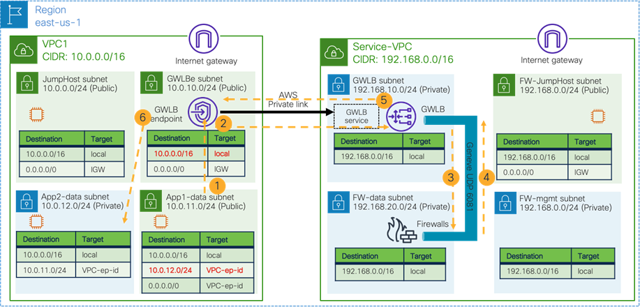
Traffic from the 10.0.12.0/24 subnet to 10.0.11.0/24 is forwarded to the GWLB endpoint based on the egress route table of the “App2-data” subnet.
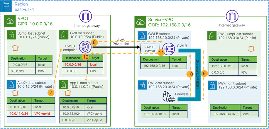
Integration with NDO and Cisco Cloud Network Controller
The previous two traffic flow examples in this section use the VPCs that are not managed by Cisco Cloud Network Controller. It is also possible to import the VPCs to Cisco Cloud Network Controller using the “Read-only” access policy, which gives the capability to automate configurations for the network connectivity from the VPCs managed by Cisco Cloud Network Controller to the “Read-only” VPCs within the site (though the configurations within the “Read-only” VPCs still need to be done accordingly outside of Cisco Cloud Network Controller). By adding the cloud site to NDO, that benefit is applicable to inter-site communication, too.
The figure below illustrates an example scenario. Infra VPC and VPC2 on the left are managed by Cisco Cloud Network Controller, whereas VPC1 and Service-VPC are not fully managed by Cisco Cloud Network Controller but are imported with the “Read-only” access policy.
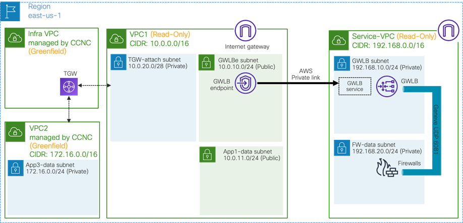
Importing the VPCs to Cisco Cloud Network Controller has the following considerations:
· Because Cisco Cloud Network Controller currently doesn’t support network and security configuration automation with AWS GWLB, the access policy must be “Read-only”, which means network and security configuration on the VPC1 and Service-VPC are not managed by Cisco Cloud Network Controller. Cisco Cloud Network Controller still automates network and security configurations for the other VPCs.
· By importing the brownfield VPCs with a “Read-only” access policy, Cisco Cloud Network Controller can automate the network and security configuration on the greenfield VPCs to reach the networks in the imported brownfield VPCs. In this example, Service-VPC doesn’t have to be imported because there is no direct communication between the greenfield VPC and the Service-VPC. Please see the route table explanation in the next sub-section for details.
· The VPC for the GWLB (Service-VPC in this example) doesn’t have to be imported to Cisco Cloud Network Controller.
· The brownfield VPC (VPC1 in this example) needs an additional subnet for each availability zone to attach the VPC to the TGW. When a VPC is attached to a TGW, one subnet from each availability zone is required. In this example, the assumption is that the “TGW-attach”, “GWLBe” and “App1-data” subnets are in the same availability zone.
· When importing VPC1 into Cisco Cloud Network Controller, it is recommended to use a separate TGW gateway subnet for each TGW VPC attachment so that a different set of network ACLs can be applied. For example, if there is another TGW VPC attachment to VPC3 from VPC1, it’s recommended to create another gateway subnet, such as 10.0.20.16/28. Please refer to the Transit gateway design best practices for details.
· There is no need to enable appliance mode on the TGW in the infra VPC managed by Cisco Cloud Network Controller. If there is another TGW in the traffic flow across availability zones, appliance mode needs to be enabled on the TGW to use the same virtual appliance. Please see the AWS Transit Gateway document for details.
East-West Traffic Flow between a Greenfield VPC and a Brownfield VPC
This sub-section explains traffic flow from a VM instance in a VPC that is managed by Cisco Cloud Network Controller, which is called a greenfield VPC, to a VM instance that is not managed by Cisco Cloud Network Controller, which is called a brownfield VPC.
Similar to the previous example, each subnet in the VPCs needs to be configured accordingly to insert a firewall in the traffic path. The figure below illustrates egress route table configuration examples.
In addition to the previous example, the brownfield VPC1 has the following additional subnets and egress route tables:
· “TGW-attach” subnet has the following egress routes:
o 10.0.0.0/16 as the local subnet (CIDR)
o 10.0.11.0/24 via the VPC endpoint (VPC-ep-id in the figure below), which is used to access VM instances in the “App1-data” subnet through a firewall.
· “GWLBe” and “App1-data” subnets have an additional egress route:
o 172.16.0.0/24 (“App3-data” subnet in the greenfield VPC “VPC2”) via the VPC endpoint (VPC-ep-id in the figure below), which is used to access the greenfield VPC through a firewall.
Greenfield VPC “VPC2” has the following subnets:
· “App3-data” subnet” has the following Egress routes:
o 172.16.0.0/16 as the local subnet (CIDR)
o 10.0.11.0/24 via the TGW, which is used to access VM instances in “App1-data” subnet through a firewall.
Note that the egress routes in VPC1 need to be configured outside of Cisco Cloud Network Controller because VPC1 is a brownfield VPC imported to Cisco Cloud Network Controller with a “Read-only” access policy, whereas the egress routes in VPC2 are automatically configured by Cisco Cloud Network Controller because VPC2 is a greenfield VPC. In this example, Service-VPC doesn’t have to be imported because there is no direct communication from VPC2 to the subnet in Service-VPC.
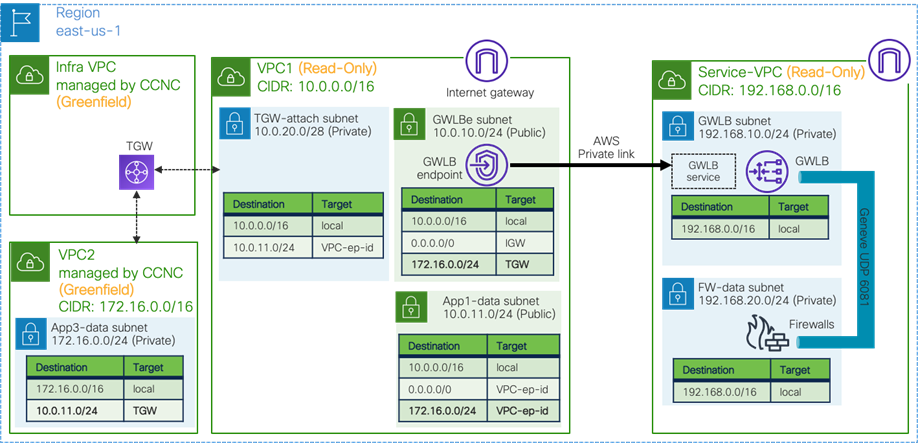
The figure below illustrates traffic flow from a VM instance in the greenfield VPC “VPC2” to a VM instance in the brownfield VPC “VPC1”.
1. Traffic from a VM instance in VPC2 arrives via the TGW in the infra VPC managed by Cisco Cloud Network Controller.
2. Traffic is forwarded to the GWLBe based on the route table of the gateway subnet (10.0.11.0/24 via VPC-ep-id in this example).
3. Traffic is forwarded to the GWLB on the Service-VPC through the AWS Private Link.
4. The GWLB forwards the traffic to one of the firewalls using Geneve encapsulation.
5. The firewall applies its security policy on the traffic and sends the traffic back to the GWLB using Geneve encapsulation.
6. The GWLB sends the traffic back to the GWLBe through the AWS Private Link.
7. The GWLBe subnet has a local route for the destination subnet (10.0.0.0/16 in this example). Thus, the traffic is forwarded to the destination.
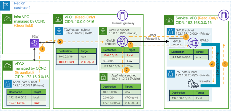
The figure below illustrates the return traffic flow from the VM instance in the brownfield VPC “VPC1” to the VM instance in the greenfield VPC “VPC2”.
8. Traffic from the VM instance in the VPC1 is forwarded to the GWLBe based on the egress route table (0.0.0.0/0 via VPC-ep-id in this example).
9. Traffic is forwarded to the GWLB on the Service-VPC through the AWS Private Link.
10. The GWLB forwards the traffic to one of the same firewalls using Geneve encapsulation. This is because Session Stickiness is enabled on the target-group associated with the firewalls.
11. The firewall applies its security policy on the traffic and sends the traffic back to the GWLB using Geneve encapsulation.
12. The GWLB sends the traffic back to the GWLBe through the AWS Private Link.
13. The GWLBe subnet has the route for the VPC2 (172.16.0.0/24 in this example) via the TGW in the infra VPC. Thus, the traffic is forwarded to the destination via the TGW in the infra VPC.
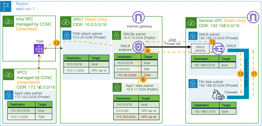
For a more detailed procedure, see:
For more information, see: