VAST Data Storage Connectivity to Cisco Nexus 9000 Series Switches in Cisco® Application Centric Infrastructure (Cisco ACI™) Mode
Available Languages
Bias-Free Language
The documentation set for this product strives to use bias-free language. For the purposes of this documentation set, bias-free is defined as language that does not imply discrimination based on age, disability, gender, racial identity, ethnic identity, sexual orientation, socioeconomic status, and intersectionality. Exceptions may be present in the documentation due to language that is hardcoded in the user interfaces of the product software, language used based on RFP documentation, or language that is used by a referenced third-party product. Learn more about how Cisco is using Inclusive Language.
- US/Canada 800-553-2447
- Worldwide Support Phone Numbers
- All Tools
 Feedback
 Feedback
Cisco ACI configuration for VAST Data storage servers
Configuring leaf switch interfaces connected to VAST Data storage servers
Configure the EPGs and bridge domains
This document contains material and data with multiple dependencies. The information may be updated as and when necessary and is subject to change without notice.
Privileged/Confidential information is contained in this document and may be subject to legal privilege. Access to this material by anyone other than those intended is unauthorized. If you are not the intended recipient (or responsible for delivery of the information to such person), you may not use, copy, distribute, or deliver to anyone this information (or any part of its contents) or take any action in reliance on it. In such case, you should destroy this information and notify Cisco immediately. If you have received this material in error, please notify us immediately and delete the material from any computer. If you or your employer does not consent to this message, please notify us immediately. Our company cannot accept responsibility for any loss or damage arising from the use of this material.
This document describes the network design considerations for VAST Data storage connected to Cisco Nexus 9000 series switches-based network with Cisco® Application Centric Infrastructure (Cisco ACI™).
This document assumes that you have a basic knowledge of Cisco ACI and Cisco NX-OS technologies.
For more information, see the Cisco ACI white papers and Cisco Nexus 9000 series switches white papers.
● Cisco ACI-related terminologies
BD: bridge domain
EPG: endpoint group
VRF: Virtual Routing and Forwarding
GARP: Gratuitous Address Resolution Protocol
● QoS-related terminologies
RDMA: Remote Direct Memory Access
RoCE: RDMA over Converged Ethernet
RoCEv2: RDMA support over Layer 3 Network
PFC: Priority Flow Control
WRED: Weighted Random Early Detection
DSCP: Differentiated Services Code Point, which is used to classify the network packets and provide Quality of Service over IP Networks
Cisco has partnered with VAST Data to onboard their storage software on Cisco UCS C225 M8 rack servers in EBox architecture. The EBox (Everything Box) is VAST Data's integrated deployment model solution, combining compute and storage capabilities into a single, compact enclosure. VAST Data supports a "Distributed and Shared Everything" (DASE) architecture that allows for horizontally scaling storage capacity and read/write performance by incrementally adding servers. To support all stages of an AI data pipeline, all protocol servers, such as NFS, S3, and SMB, are enabled.
Figure 1 shows the overall network connectivity of storage server and the BOM for a single EBox with storage switches and frontend switches. For the data path, each server uses two NVIDIA BlueField-3 B3220L 2x200G NICs: NIC0 is used for Storage-Internal and Storage-Broadcast network within the servers, allowing any server to access storage drives from any other server, and NIC1 is used for the Storage-External network, supporting client traffic such as NFS, S3, and SMB. The 1G BMC and 10G x86 management ports are connected to a management leaf switch.
As the cluster size increases, the number of leaf switches and EBoxes will linearly increase.
Beginning with Cisco ACI release 6.1(4h), Nexus 9000 series switches support all the requirements for VAST Data storage connectivity.
Cisco Nexus 9000 series switches can be used for frontend switches and storage switches in either NX-OS mode or Cisco ACI mode. The Frontend switches are used to configure the Storage-External network. The Storage switches are used to configure the Storage-Internal network and Storage-Broadcast network between the VAST Data storage servers. In the case of Cisco NX-OS mode, the use of the spine-leaf topology is not mandatory even though it is a common design, whereas the Cisco ACI mode requires the spine-leaf topology.
This document details the VAST Data storage network design with Cisco Nexus 9000 series switches in Cisco ACI mode. This document describes the use of a dedicated Cisco ACI fabric for frontend switches and a separate dedicated Cisco ACI fabric for storage switches.
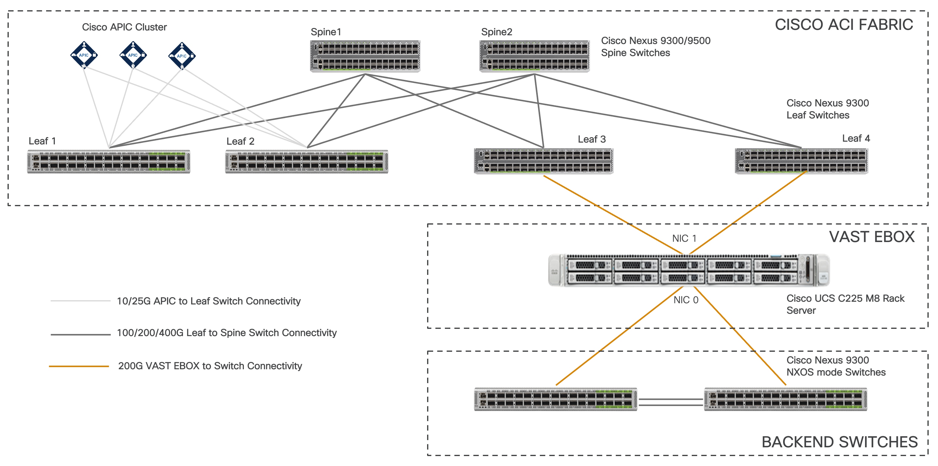
Figure 1 Topology example with Nexus 9000 series switches in Cisco ACI mode
This document provides information, education, and guidance for connecting the VAST Data storage servers to an existing Cisco Nexus 9000 series switch-based network in the data centers. The document provides fundamental information and recommended configurations based on internal testing of the solution. This document does not cover the installation and configuration of Cisco ACI or NX-OS based infrastructure, nor does it detail the setup of VAST Data storage.
This document uses Cisco UCS C225 M8 servers as the VAST Data storage servers. For more information, see the VAST Data on Cisco UCS data sheet.
The frontend and storage switches can be managed using a Cisco controller such as Cisco Application Policy Infrastructure Controller (APIC) and Cisco Nexus Dashboard Fabric Controller (NDFC). The VAST Data storage server requires the frontend and storage switches to be configured with RoCEv2. The RoCEv2 configuration on the NX-OS mode switches is not covered as part of this document. For more information, see RoCE Storage Implementation over NX-OS VXLAN Fabrics.
This section introduces the technologies that are used in the solution, which are described in this document.
Cisco ACI is an evolutionary leap from SDN's initial vision of operational efficiency through network agility and programmability. Cisco ACI has industry leading innovations in management automation, programmatic policies, and dynamic workload provisioning. The ACI fabric accomplishes this with a combination of hardware, policy-based control systems, and closely coupled software to provide advantages that are not possible in other architectures.
Cisco ACI takes a policy-based systems approach to operationalizing the data center network. The policy is centered around the needs (reachability, access to services, and security policies) of the applications. Cisco ACI delivers a resilient fabric to satisfy today's dynamic applications.
The Cisco ACI fabric is a leaf-and-spine architecture where each leaf switch connects to every spine switch using high-speed 40/100/400-Gbps Ethernet links, with no direct connection between the spine switches or leaf switches. The ACI fabric is a routed fabric with a VXLAN overlay network, where every leaf switch is a VXLAN Tunnel Endpoint (VTEP). Cisco ACI provides both Layer 2 (L2) and Layer 3 (L3) forwarding across this routed fabric infrastructure.
These are the ACI fabric components:
● Cisco APIC:Cisco APIC: Cisco Application Policy Infrastructure Controller (APIC) is the unifying point of automation and management for the Cisco ACI fabric. Cisco APIC is a centralized, clustered controller that provides centralized access to all fabric information, optimizes the application lifecycle for scale and performance, and supports flexible application provisioning across physical and virtual resources. Cisco APIC exposes northbound APIs through XML and JSON and provides both a command-line interface (CLI) and a GUI, which utilize the APIs to manage the fabric.
● Leaf Switches:Leaf Switches: The ACI leaf switch provides physical connectivity for servers, storage devices, and other access layer components, and enforces the ACI policies. Leaf switches also provide connectivity to an existing enterprise or a service provider infrastructure. The leaf switches provide options starting at 1G up through 400G Ethernet ports for connectivity.
● Spine Switches:Spine Switches: In ACI, spine switches provide the mapping database function and connectivity between leaf switches. A spine switch can be the modular Cisco Nexus 9500 series equipped with ACI ready line cards or a fixed form-factor switch, such as the Cisco Nexus 9332D-GX2B. Spine switches provide high-density 40/100/400 Gigabit Ethernet connectivity to the leaf switches.
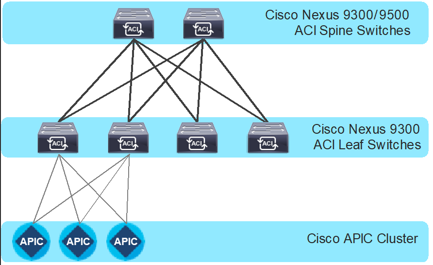
Figure 2 Cisco ACI fabric components
VAST Data uses a Disaggregated, Shared-Everything (DASE) architecture that separates stateless compute (CNodes) from persistent storage (DNodes). This architecture enables high performance, scalability, and efficiency by allowing any compute node to access any data directly, eliminating metadata bottlenecks and enabling advanced data reduction and protection techniques.
With the introduction of the EBox, VAST Data can take this architecture to the next level by integrating the capabilities of CNodes and DNodes into a single, more efficient hardware platform. The EBox is designed to address the growing needs of hyperscalers and CSPs that require infrastructure capable of handling massive data volumes and complex workloads. By combining the best features of its predecessors into a more compact form factor, the EBox not only saves valuable rack space but also enhances the overall performance and resilience of the data center.
This section describes the logical and physical connectivity of the VAST Data storage servers with the Nexus 9000 series switch-based network.
Each Cisco UCS C225 M8 server is connected to a pair of Cisco Nexus 9000 frontend switches through NIC 1 using dual 200 Gbps connections. In this example, the Cisco Nexus 9364D-GX2A Switches in Cisco ACI mode carries all the Storage-External network, supporting client traffic such as NFS, S3, and SMB. You can also use Top-of-Rack switches in NX-OS mode with Nexus Dashboard Fabric Controller (NDFC).
Each Cisco UCS C225 M8 server also connects to a pair of Cisco Nexus 9000 storage switches through NIC 0 using dual 200 Gbps connections. In this example, Cisco Nexus 9364D-GX2A switches in Cisco ACI mode carries Storage-Internal network traffic within the servers, allowing any server to access storage drives from any other server. The Storage-Internal network traffic is primarily switched locally at the leaf switch because every server connects to every leaf switch.
Physical server management, such as Cisco Integrated Management Controller (CIMC) on Cisco UCS C-series, is facilitated through an out-of-band (OOB) management network that connects the server's dedicated management port to an OOB management switch with 1Gbps links. Apart from CIMC, a host management port on the Cisco UCS servers are connected to the OOB management switch.
The following diagram illustrates a high-level physical architecture design:
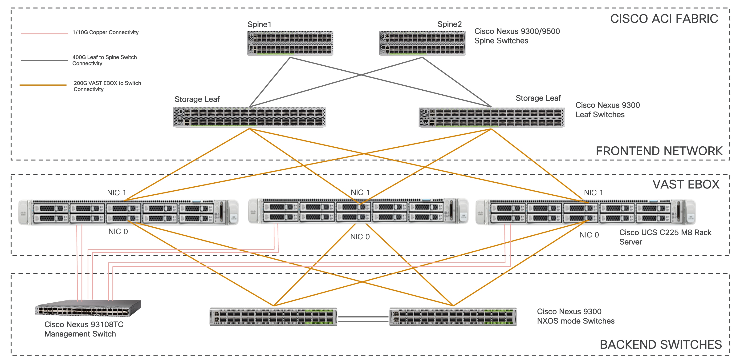
Figure 3 Physical architecture
Note: Configuration of frontend switches and storage switches, if used in NX-OS mode, is not covered in this document.
Physical connectivity considerations include the following:
● All the switches are configured for a MTU size of 9216. The MTU size for the packets sent on the network are controlled by the endpoints.
VAST Data storage cluster uses the following four logical networks:
● Storage-Internal network: The VAST Data storage clusters use NVMe over RDMA for node-to-node communications over 200 Gbps Ethernet. A VLAN is trunked across all the NIC0 interfaces of all the VAST Data storage nodes. This network does not have an anycast gateway IP assigned. The switch interfaces are not configured for any port channel or virtual port channel (vPC) and they are configured as standalone interfaces.
● Storage-Broadcast network: This network also does not have an anycast gateway IP address assigned. The VLAN is untagged on all the NIC0 interfaces of the VAST Data Storage nodes.
● Storage-External network: The Storage-External network carries file, object, or database requests from client hosts to the VAST Data storage nodes. VAST Data storage supports multitenancy and hence each client can have their unique network (VLAN). These networks are passed as trunk on the NIC1 interfaces of the VAST Data storage nodes. VAST also recommends enabling Gratuitous ARP on this network. The switch interfaces are not configured for any port channel or vPC and they are configured as standalone interfaces.
The Storage-External network must be configured with an IP subnet. Each node in the cluster is provisioned with a set of virtual IP (VIP) addresses. In the event a node becomes unavailable, its associated VIP addresses are rebalanced and reassigned to the remaining active nodes. To optimize resiliency and maintain uniform traffic distribution during node failures, VAST recommends assigning an IP subnet with a VIP address count 2 to 4 times greater than the total number of nodes, ensuring the displaced VIP addresses can be redistributed across multiple nodes without overloading any single member.
Note: The minimum cluster size of VAST EBox is 8 nodes.
● Management network: The management network carries management traffic to the cluster, including DNS and authentication traffic.
● CIMC/ILO network: The CIMC network is used for managing and monitoring the hardware in the cluster.
Figure 4 shows a logical representation of the networks to be created in the ACI tenant. In this sample topology, there is one client tenant named CUST001_TN and a VRF instance called CUST001_VRF. The STORAGE-EXTERNAL bridge domain and EPG are created to provision the Storage-External network of VAST Data storage. The client's host and the VAST EBox have static binding in the same EPG. A separate bond interface on the client host can be used to connect to the external client network.
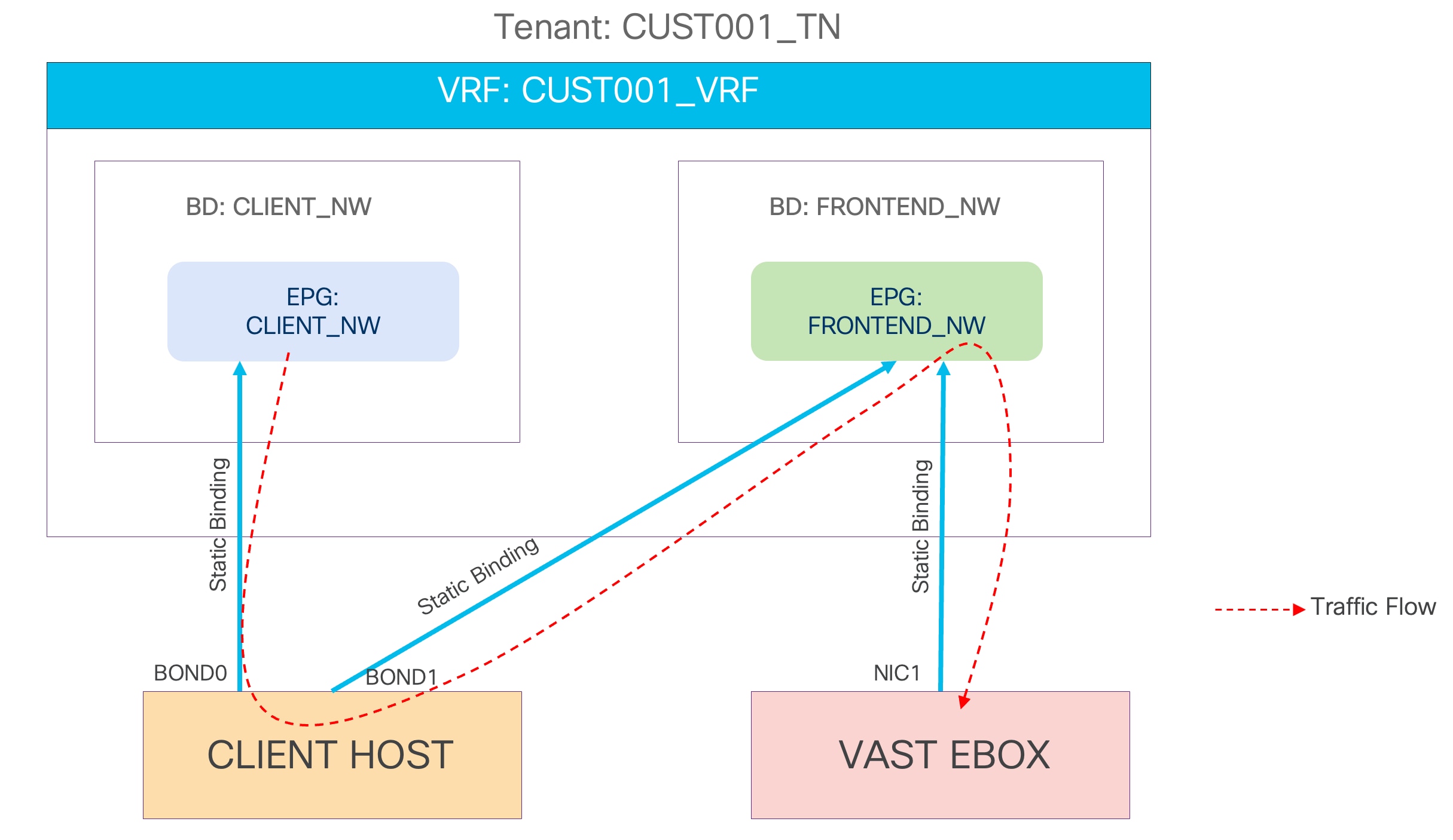
Figure 4 VAST Data Storage-External network logical diagram
VAST recommends RoCEv2 to be enabled on the Storage-External and Storage-Internal network. The following configurations are to be enabled on the Cisco ACI to support RoCEv2:
● No-Drop-DSCP Match Policy and Priority Flow Control (PFC) to be enabled in the interface access policies.
● Both these policies are supposed to be attached to the interface policy group created for VAST Data interfaces.
● No-Drop-DSCP match control to be enabled in the QoS class.
● RoCEv2 supports only QoS Level 1 or 2 inside the Cisco ACI fabric.
● Level 1 or Level 2 QoS Class Policy to be configured with Weighted Random Early Detection (WRED) and Explicit Congestion Notification (ECN).
● VAST Data tags all the storage traffic with a DSCP marking of 26. Hence, PFC No-Drop-DSCP to be configured with DSCP 26.
● Level 6 QoS class for control plane traffic with a strict priority queue.
● Custom QoS policy attached to STORAGE-EXTERNAL EPG which matches DSCP 26 traffic to Level 1 or 2 and CS6 (Control Plane) traffic to Level 6.
This section provides a detailed procedure to configure the Cisco ACI fabric. It also explains how to add new components to an existing Cisco ACI fabric.
This section explains how VAST Data storage servers can connect to the Cisco ACI fabric by using the EPG and bridge domains.
This design assumes that the customer already has the Cisco ACI fabric in place with spine switches and Cisco APICs deployed and connected through a pair of leaf switches.
Figure 5 illustrates an ACI interface configuration example along with the domain and the VLAN pool configuration. Although it's possible to use different interfaces on a pair of ToR switches, this document uses the same interfaces: node-101 (ethernet1/11 and 1/12) and node-102 (ethernet1/11 and 1/12).
Note: This document does not cover the Cisco ACI fabric deployment and installation of VAST Data software on the UCS servers.
Table 1 lists the hardware and software releases that are used in this solution.
Table 1 Hardware and software releases
| Layer |
Hardware |
Software release |
Comments |
| Cisco ACI |
Cisco APIC-L4 |
6.1(4h) |
ACI controller |
| Cisco ACI |
N9K-9364D-GX2A |
16.1(4h) |
Frontend switches |
| Cisco ACI |
N9K-9364D-GX2A |
16.1(4h) |
Storage switches |
| VAST Data software |
Cisco UCS C225 M8 rack servers |
12.14.17-1818066 |
VAST OS |
Cisco ACI configuration for VAST Data storage servers
This section explains how to configure Cisco ACI for VAST Data storage servers with the assumption that the ACI fabric and Cisco APICs already exist in the customer's environment. This document does not cover the configuration required to bring the initial ACI fabric online.
The following are the configuration steps to configure Cisco ACI for VAST Data storage servers:
● Configuring leaf interfaces connected to VAST Data storage servers
● Configure QoS
● Configure EPGs and bridge domains
● Apply Custom QoS policy to EPG
Configuring leaf switch interfaces connected to VAST Data storage servers
This section contains the following steps:
● Create VLAN pool for VAST Data storage
● Configure physical domain
● Create Attachable Access Entity Profile
● Create LLDP policy
● Create interface Priority Flow Control policy
● Create No-Drop-DSCP Match policy
● Create interface policy group for Interfaces connected to VAST Data storage servers
● Associate the interface policy group to the leaf interfaces connected to VAST Data storage servers
Figure 5 summarizes the topology, interface, and physical domain configuration parameters used in this section. The connection uses four 200 Gbps interfaces between ACI leaf switches and VAST Data storage servers. This example also includes one client host that has two 200 Gbps interfaces connected to the same ACI leaf switches.
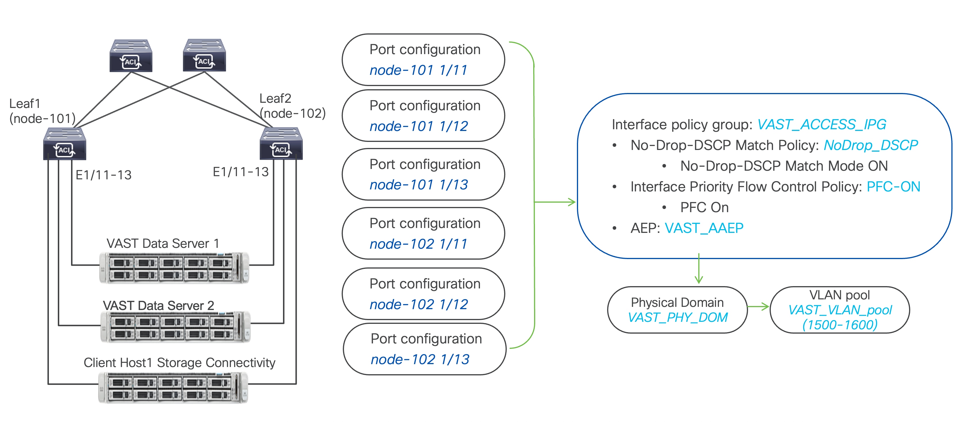
Figure 5 Interface and physical domain configuration for VAST Data storage servers
Table 2 summarizes the customer tenant configuration parameters that are used in this section. The ACI leaf switches serve as the gateway to the VAST Data storage Storage-External network. The CLIENT_NW BD and EPG are only for the representational purpose of the client network. The client network can be part of a different ACI fabric, and the VAST Data Storage-External network can be part of a dedicated ACI fabric depending on the respective organization's network design.
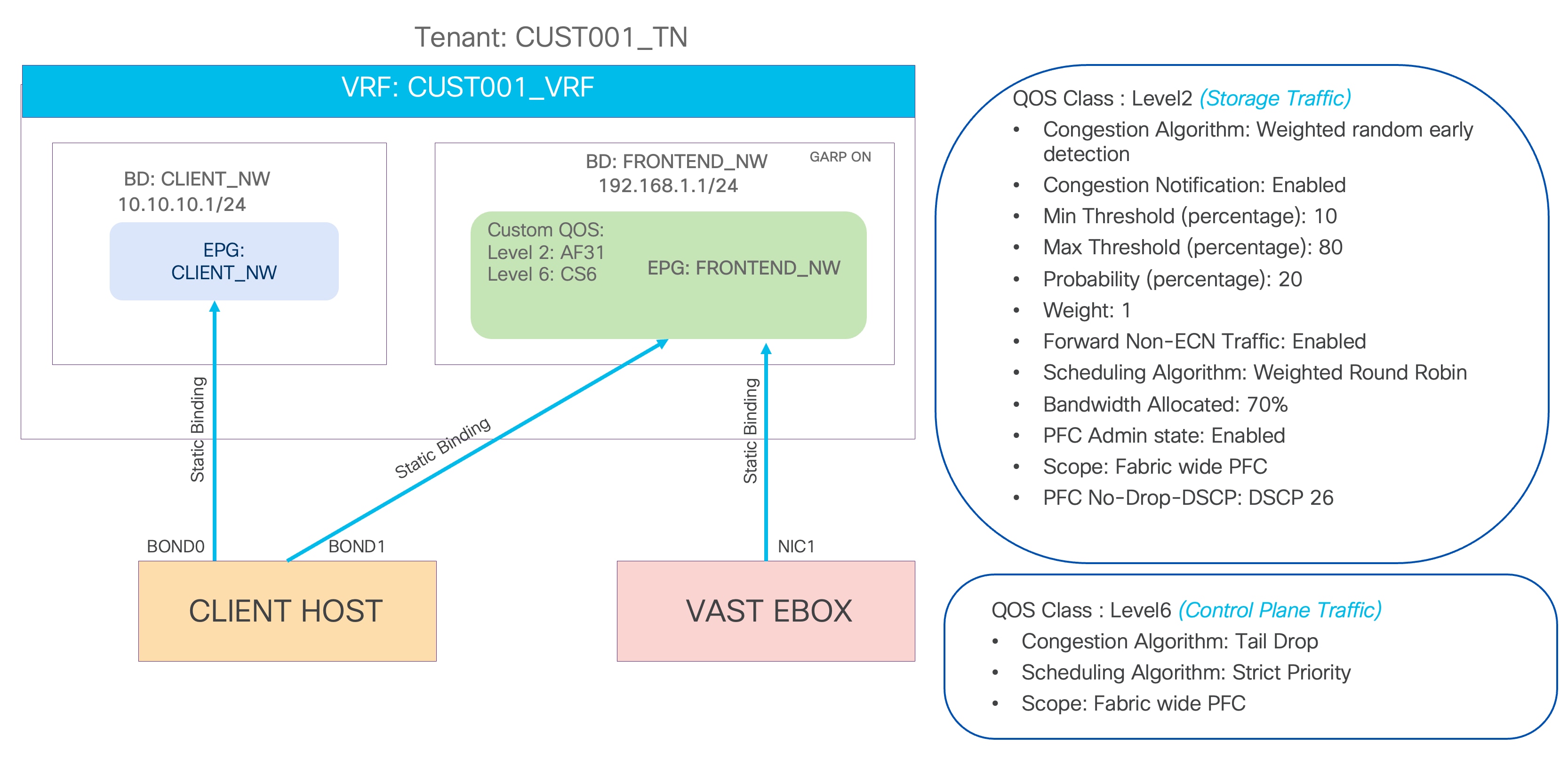
Figure 6 Tenant configuration example
Table 2 VAST Data storage customer tenant configuration example
| Property |
Name |
| Tenant |
CUST001_TN |
| Tenant VRF instance |
CUST001_VRF |
| Bridge domain |
STORAGE-EXTERNAL in CUST001_VRF (subnet 192.168.1.1/24) |
| Leaf nodes and interfaces |
Node 101 and 102 ethernet 1/11, 1/12, and 1/13 |
| EPG |
EPG STORAGE-EXTERNAL in BD STORAGE-EXTERNAL (VLAN 1500 tagged) |
| Contract |
Not required |
Table 3 VAST Data storage southbound tenant configuration example
| Property |
Name |
| Tenant |
STORAGE_TN |
| Tenant VRF instance |
STORAGE_VRF |
| Bridge domain |
STORAGE-INTERNAL in STORAGE_VRF (subnet not required) |
| Bridge domain |
STORAGE-BROADCAST in STORAGE_VRF (subnet not required) |
| EPG |
EPG STORAGE-INTERNAL in BD STORAGE-INTERNAL (VLAN 69 tagged) |
| EPG |
EPG STORAGE-BROADCAST in BD STORAGE-BROADCAST (VLAN 10 untagged) |
| Contract |
Not required |
Create a VLAN pool for the VAST Data storage physical domain
In this section, you will create a VLAN pool to enable connectivity to the VAST Data storage.
To configure a VLAN pool to connect the VAST Data storage servers to the ACI leaf switches, follow these steps:
1. From the Cisco APIC top navigation menu, select Fabric > Access Policies.
2. From the left navigation pane, expand and select Pools > VLAN.
3. Right-click and select Create VLAN Pool.
4. In the Create Pool pop-up window, enter a name (for example, VAST_VLAN_POOL) and for Allocation Mode, select Static Allocation.
5. For Encap Blocks, use the [+] button on the right to add VLANs to the VLAN Pool. In the Create Ranges pop-up window, configure the VLANs that need to be configured from the leaf switches to the VAST Data storage servers. Leave the remaining parameters as they are.
6. Click OK.
7. Click Submit.
Configure a physical domain for VAST Data storage
To create a physical domain type, connect to VAST Data storage servers, follow these steps:
1. From the Cisco APIC top navigation menu, select Fabric > Access Policies.
2. From the top navigation menu, select Fabric > Access Policies.
3. From the left navigation pane, expand and select Physical and External Domains > Physical Domains.
4. Right-click Physical Domains and select Create Physical Domain.
5. In the Create Physical Domain pop-up window, enter a name for the domain (for example, VAST_PHY_DOM). For the VLAN Pool, select the previously created VLAN Pool (for example, VAST_VLAN_POOL) from the drop-down list.
6. Click Submit.
Create an Attachable Access Entity Profile for VAST Data storage physical domain
To create an Attachable Access Entity Profile (AAEP), follow these steps:
1. From the Cisco APIC top navigation menu, select Fabric > Access Policies.
2. From the left navigation pane, expand and select Policies > Global > Attachable Access Entity Profiles.
3. Right-click and select Create Attachable Access Entity Profile.
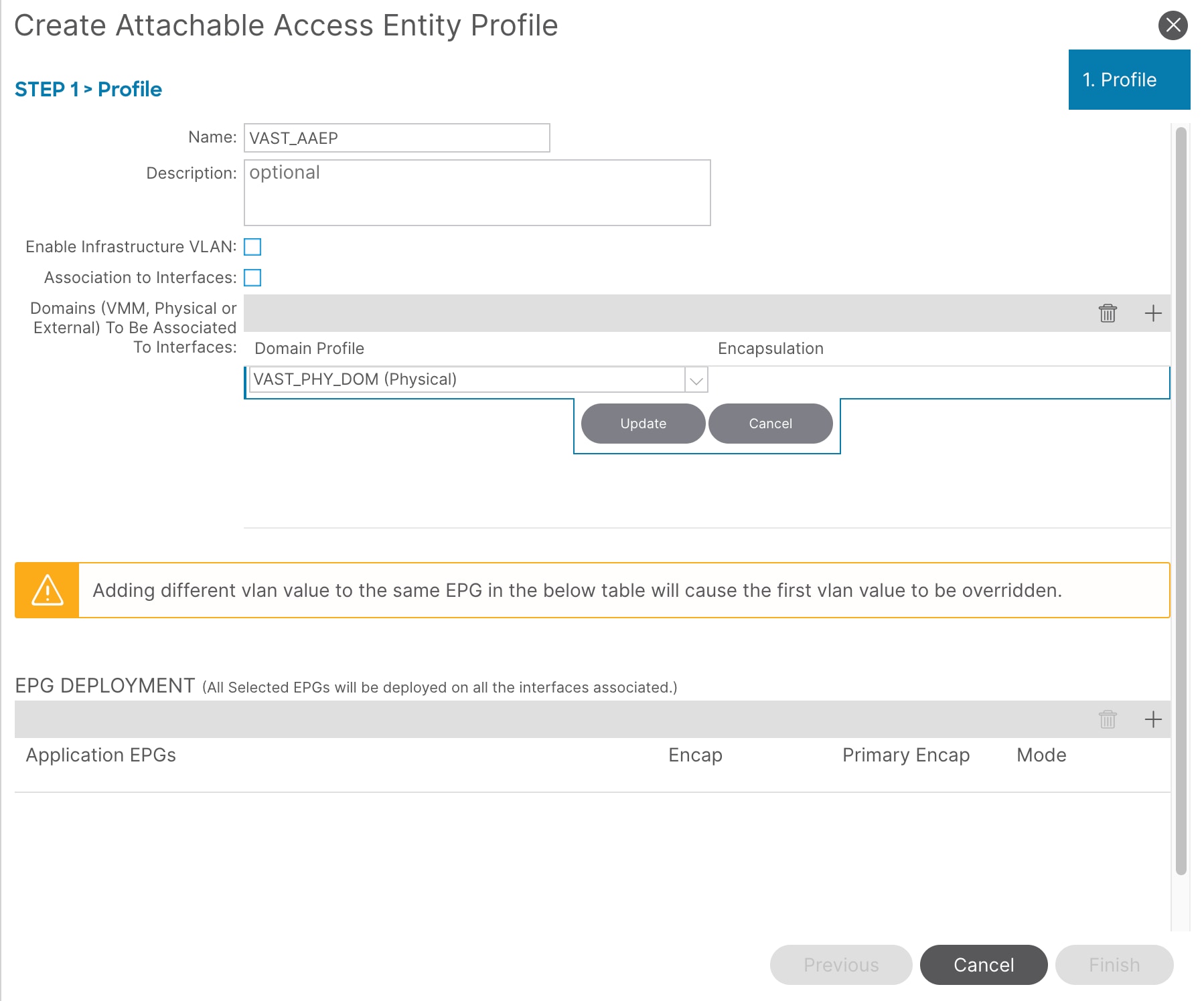
4. In the Create Attachable Access Entity Profile pop-up window, enter a name (for example, VAST_AAEP) and uncheck Enable Infrastructure VLAN and Association to Interfaces.
5. For the Domains, click the [+] on the right-side of the window and select the previously created domain from the drop-down list below Domain Profile.
6. Click Update.
7. You should now see the selected domain and the associated VLAN Pool as shown below.
8. Click Next. This profile is not associated with any interfaces currently because Association to Interfaces is unchecked at step 4 above. They can be associated after the interfaces are configured in an upcoming section.
9. Click Finish.
Create an LLDP interface policy
To create an LLDP policy, follow these steps:
1. From the Cisco APIC top navigation menu, select Fabric > Access Policies.
2. From the left navigation pane, expand and select Policies > Interfaces > LLDP Interfaces.
3. Right-click and select Create LLDP Interface Policy.
4. In the Create LLDP Interface Policy pop-up window, enter a name (for example, LLDP_ENABLED).
5. Select Enable for Transmit State.
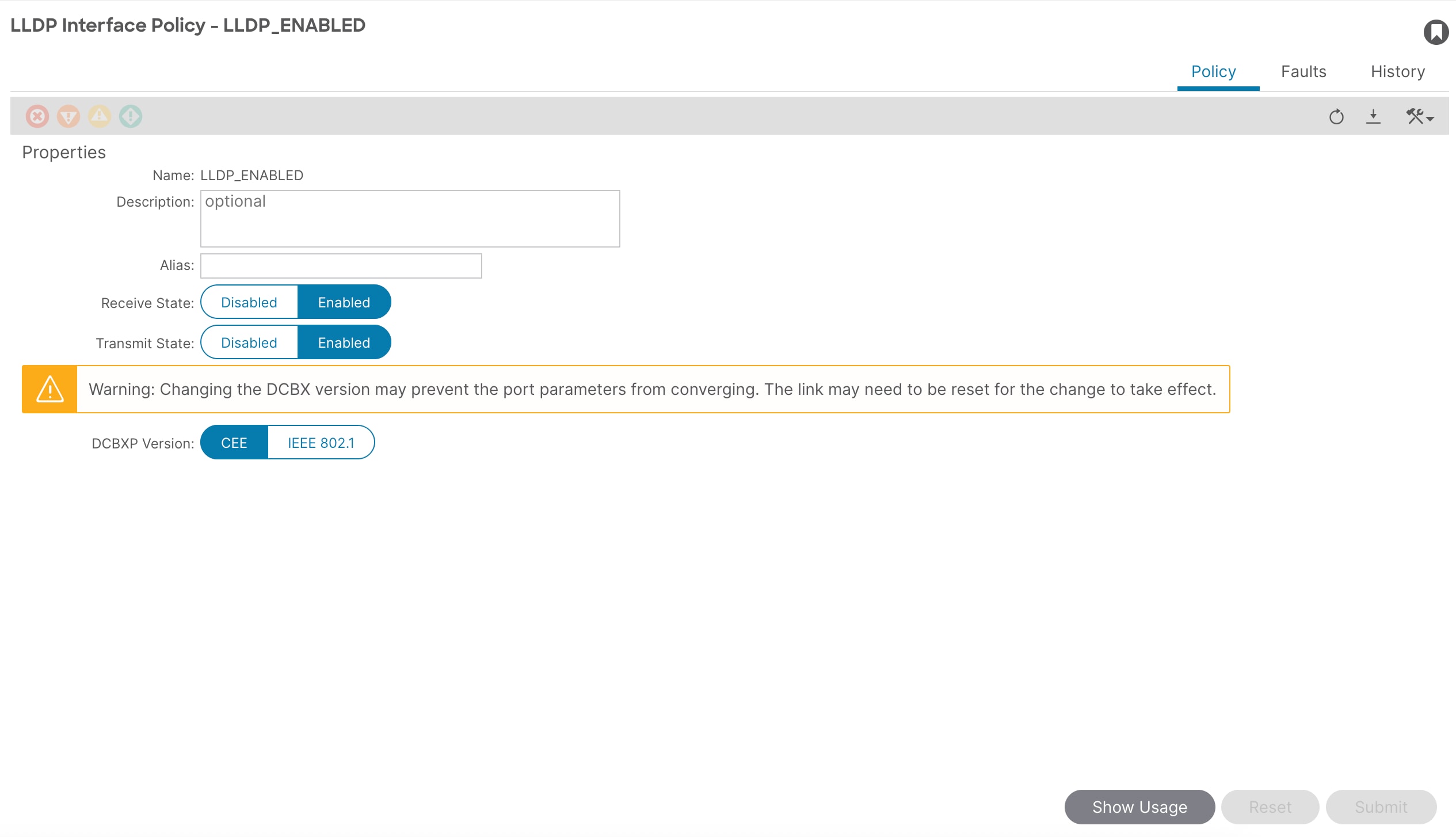
6. Click Submit.
Create an Interface Priority Flow Control policy
To create a PFC policy to enable PFC on leaf downlinks, follow these steps:
1. From the Cisco APIC top navigation menu, select Fabric > Access Policies.
2. From the left navigation pane, expand and select Policies > Interface > Priority Flow Control.
3. Right-click and select Create Priority Flow Control Policy.
4. In the Create Priority Flow Control Policy pop-up window, enter a name (for example PFC-ON) and select On. PFC and WRED with ECN are required to enable support for RoCEv2 on the ACI fabric.
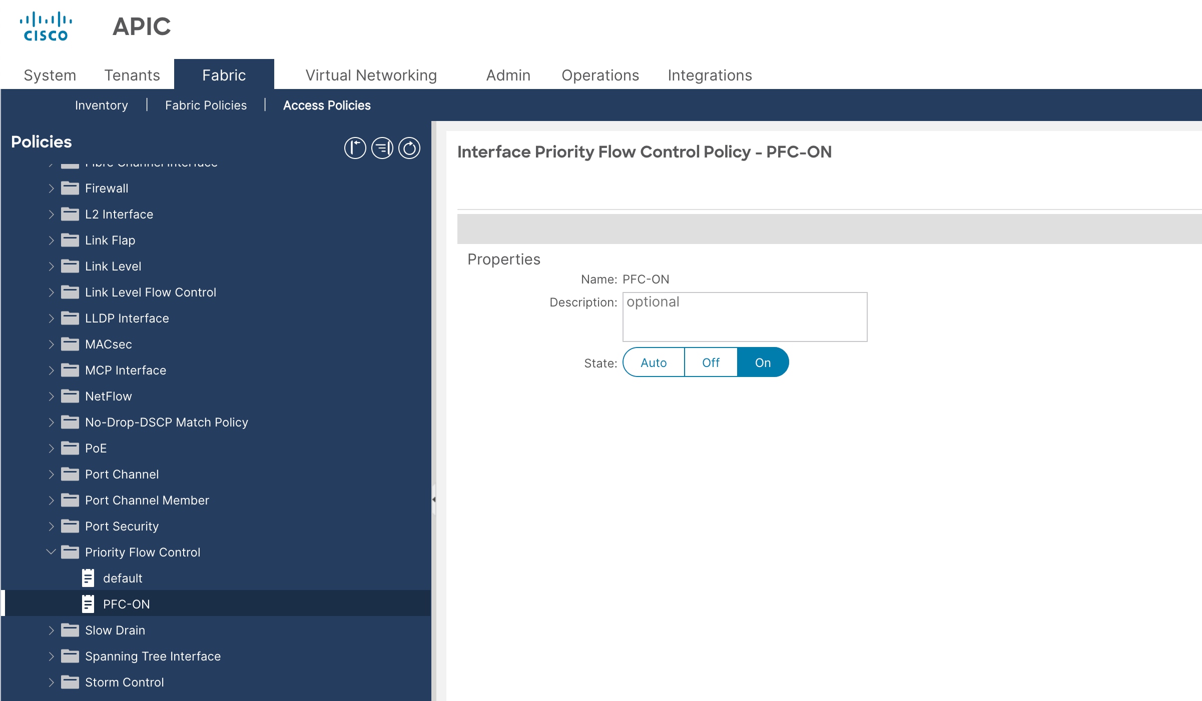
5. Click Submit.
Create a no-drop-DSCP match policy
To create an interface policy group to enable PFC on leaf downlinks, follow these steps:
1. From the Cisco APIC top navigation menu, select Fabric > Access Policies.
2. From the left navigation pane, expand and select Policies > Interface > No-Drop-DSCP Match Policy.
3. Right-click and select Create No-Drop-DSCP Match Policy.
4. In the Create No-Drop-DSCP Match Policy pop-up window, enter a name (for example NoDrop_DSCP) and select On.
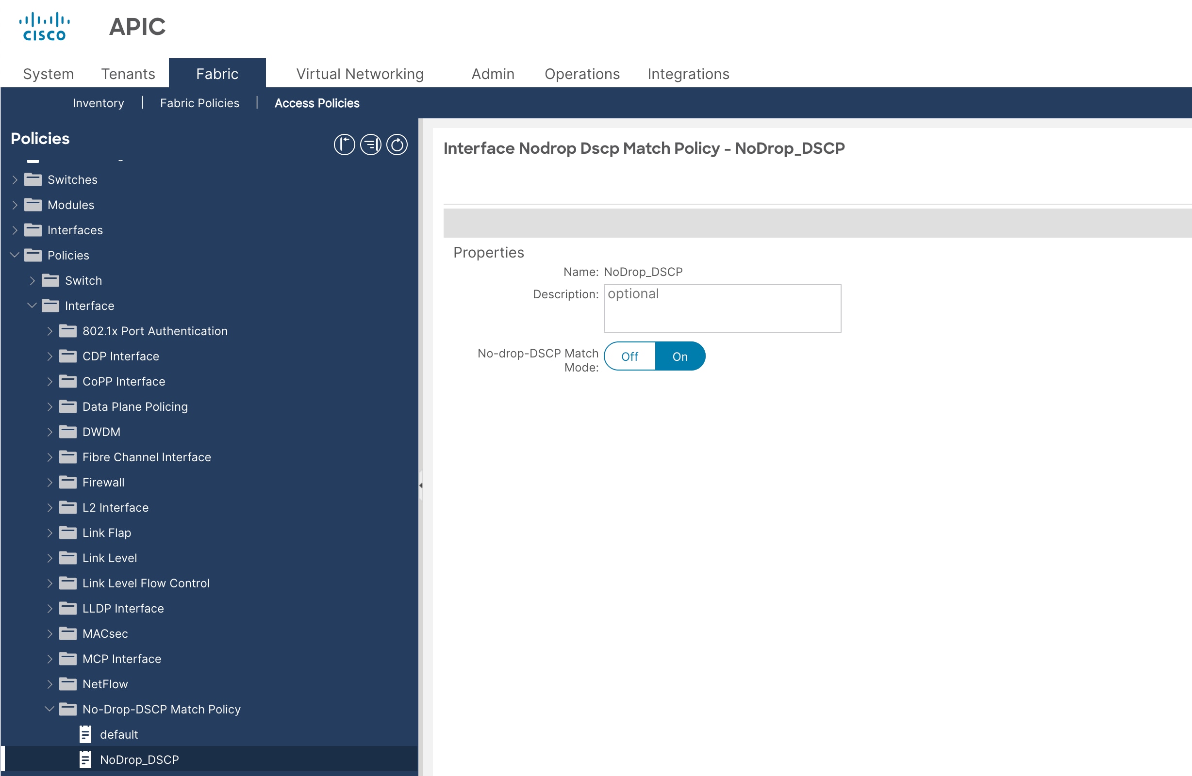
5. Click Submit.
Create a link level policy
To create a link level policy to enable specific port speed on leaf downlinks, follow these steps:
1. From the Cisco APIC top navigation menu, select Fabric > Access Policies.
2. From the left navigation pane, expand and select Policies > Interface > Link Level.
3. Right-click and select Create Link Level Policy.
4. In the Create Link Level Policy pop-up window, enter a name (for example 200G_AUTO) and select these:
a. Speed: 200 Gbps [Support for 200 Gbps port speed added in ACI release 6.1(4h)]
b. Auto Negotiation: ON
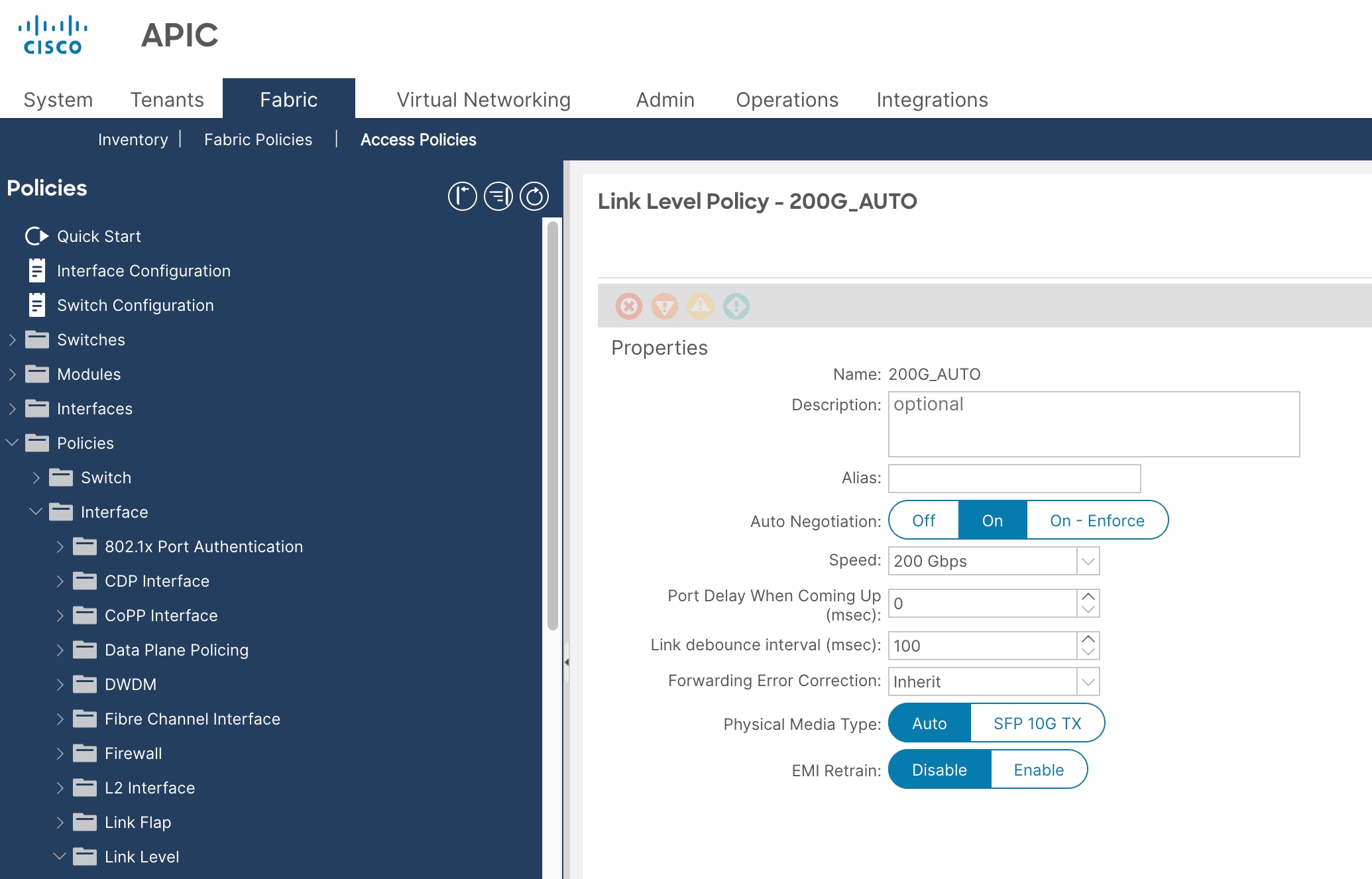
5. Click Submit.
Create an interface policy group for interfaces connected to VAST Data storage servers
To create an interface policy group to connect to VAST Data storage servers, follow these steps:
1. From the Cisco APIC top navigation menu, select Fabric > Access Policies.
2. From the left navigation pane, expand and select Interfaces > Leaf Interfaces > Policy Groups > Leaf Access Port.
3. Right-click and select Create Leaf Access Port Policy Group.
4. In the Create Leaf Access Port Policy Group pop-up window, enter a name (for example VAST_ACCESS_IPG) and the applicable interface policies from the drop-down list for each field.
5. For the Attached Entity Profile, LLDP Policy, and Priority Flow Control fields, select the previously created AAEP, LLDP policy, and priority flow control policy (for example, VAST_AAEP, LLDP_ENABLED, PFC-ON and NoDrop_DSCP).
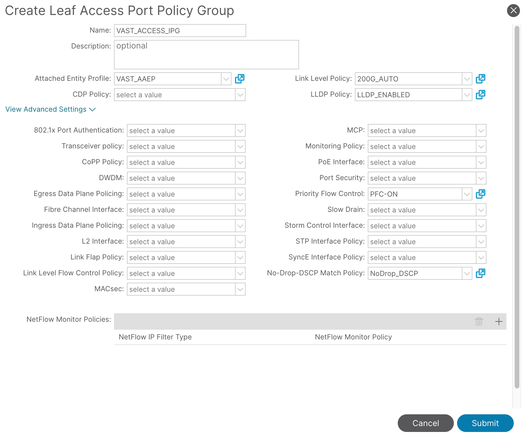
6. Click Submit.
To configure leaf switch interfaces connected to VAST Data storage servers, follow these steps:
1. From the Cisco APIC top navigation menu, select Fabric > Access Policies > Interfaces > Leaf Interfaces > Profiles.
2. Right-click and select Create Leaf Interface Profile.
3. In the Create Leaf Interface Profile pop-up window, enter a name (for example 101_102) and then click '+' to add the interface selectors.
4. In the Interface Selector pop-up window, enter a name (for example 101_102) and then enter these details:
a. Policy Group: VAST_ACCESS_IPG
b. Port Blocks: 1/11-13
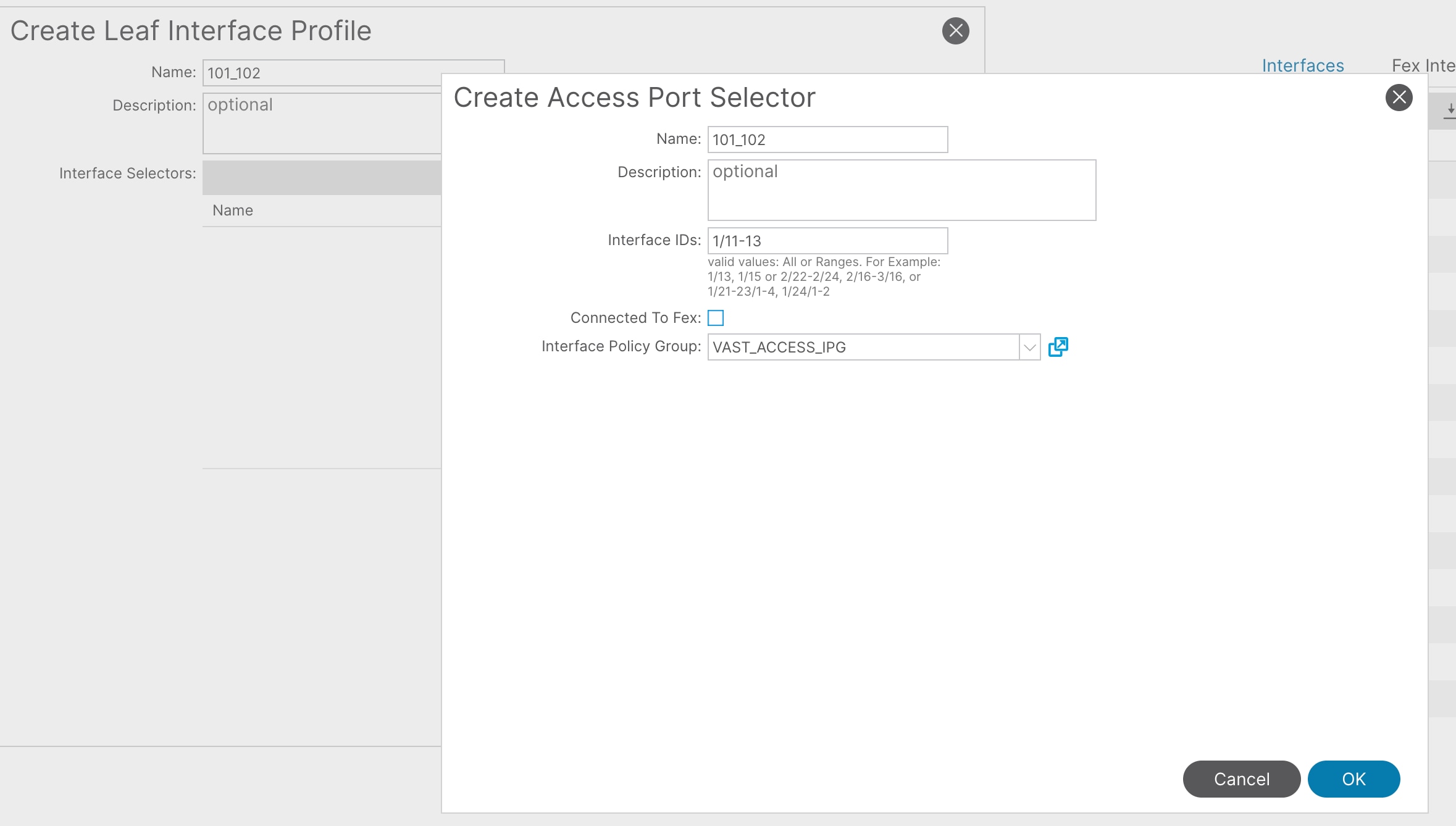
5. Click OK and then Submit.
6. Navigate to Fabric > Access Policies > Switches > Leaf Switches > Profiles.
7. Right-click and select Create Leaf Profile.
8. In the Leaf Profile pop-up window, enter a name (for example 101_102) and then enter these details:
a. Leaf Selectors Name: 101_102
b. Blocks: 101-102
c. Associated Interface Profiles: 101_102
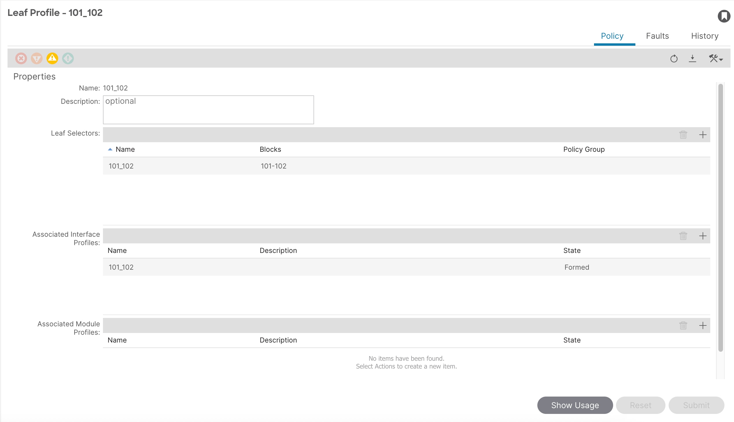
9. Click Submit.
Configure QoS
This document uses the following ACI QoS configurations as an example.
● Level2 for RDMA (storage) traffic (Traffic comes with DSCP 26 marked by VAST Data storage)
◦ PFC is enabled
◦ PFC No-Drop-DSCP: DSCP 26
◦ Bandwidth reservation: 70%
◦ Congestion Algorithm is Weighted Random Early Detection
◦ Congestion Notification is Enabled
● Level6 for control plane communication (traffic comes with DSCP 48 marked by VAST Data storage)
◦ PFC is not enabled
◦ Congestion Algorithm is Tail Drop
◦ Scheduling Algorithm is Strict Priority
● Level3 (default) for other traffic
◦ PFC is not enabled
◦ Bandwidth reservation: 30%
◦ Congestion Algorithm is Tail Drop
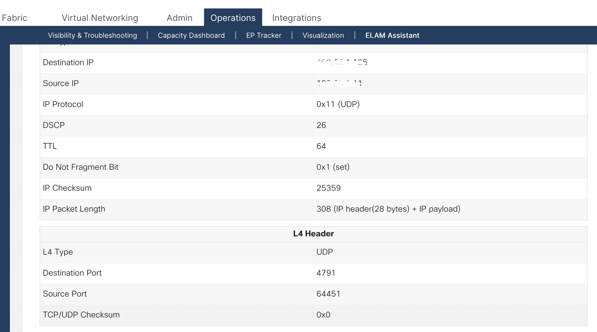
The following image captured from the ELAM assistant on Cisco ACI in a lab environment shows VAST Data storage marks the storage traffic with DSCP 26. All QoS values mentioned in this document are for explanation purposes and can be modified as per your network environment.
The Cisco ACI fabric supports six user-configurable QoS levels (Level1-6).
Table 4 Cisco ACI QoS levels
| Class of Service |
ACI QoS Level |
Doc1p (Cos) Marking in VXLAN Header |
DEI Bit** |
| 0 |
Level 3 (default) |
0 |
0 |
| 1 |
Level 2 |
1 |
0 |
| 2 |
Level 1 |
2 |
0 |
| 4 |
Level 6 |
2 |
1 |
| 5 |
Level 5 |
3 |
1 |
| 6 |
Level 4 |
5 |
1 |
**The Drop Eligible Indicator (DEI) bit is a 1-bit field that is used to indicate frames that are eligible to be dropped during traffic congestion. The CoS value (3 bits) + DEI value (1 bit) represents the QoS class.
Configure QoS Classes
To configure Cisco ACI QoS classes, follow these steps:
1. From the Cisco APIC top navigation menu, select Fabric > Access Policies.
2. From the left navigation pane, expand Policies > Global > QoS Class and select one of the levels. For example, select level2 for storage traffic.
3. In the Congestion Algorithm field, select Weighted random early detection.
4. In the Congestion Notification field, select Enabled.
5. Enter the values for Min Threshold (percentage), Max Threshold (percentage), Probability (percentage) and Weight. For example, enter Min:10, Max: 80, Probability: 20, and Weight: 1.
6. In the Forward Non-ECN Traffic field, select Enabled.
7. In the Scheduling algorithm field, from the drop-down list, choose Weighted round robin. This is the default configuration.
8. In the Bandwidth allocation (in %) field, enter a number. For example, enter 70 for storage traffic.
9. If PFC is not required in the class, leave the PFC Admin State box unchecked.
10. If PFC is required in the class, perform these substeps:
a. Check the PFC Admin State box.
b. In the No Drop-Cos field, select the Cos value. For example, select Cos 3.
c. In the PFC No-Drop-DSCP field, select the DSCP value. For example, select DSCP 26 for VAST Data storage.
d. For the Scope buttons, select Fabric-wide PFC. If the traffic is within the same leaf switch, IntraTor PFC is also fine.
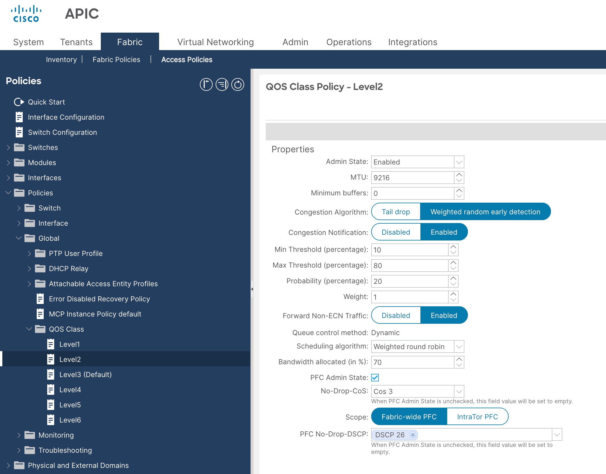
11. Click Submit.
12. From the left navigation pane, expand Policies > Global > QoS Class and select another level. For example, select level6 for control plane traffic.
13. In the Congestion Algorithm field, select Tail drop.
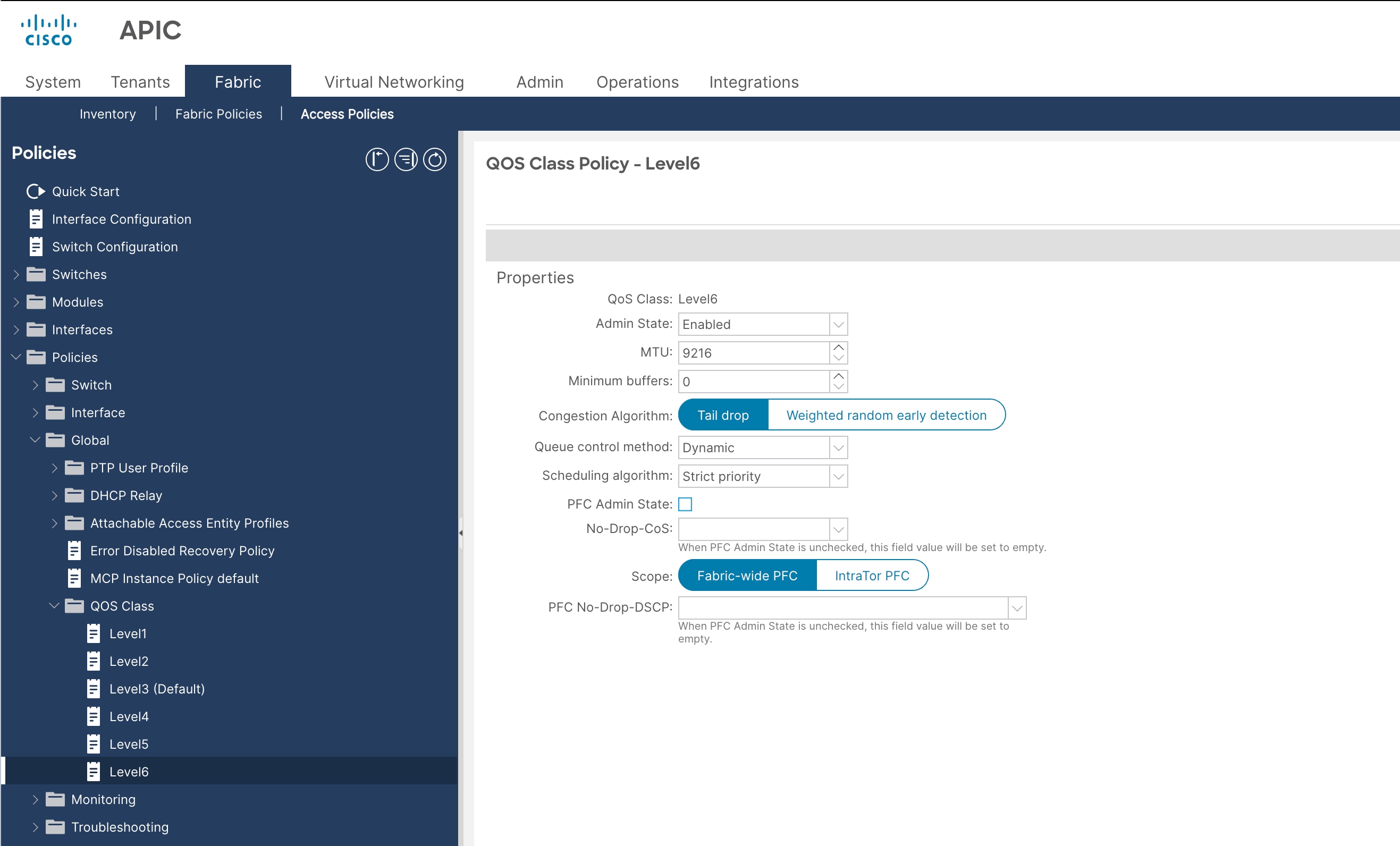
14. In the Scheduling algorithm field, select Strict priority and PFC Admin State: unchecked.
15. Navigate to Level3 (Default) for other traffic (client network traffic in this example) with 30% bandwidth reservation configuration. If the ACI fabric is dedicated only for storage traffic, 30% bandwidth reservation for other traffic is not required. In that scenario, bandwidth reservation for storage traffic in level 2 can be further increased.
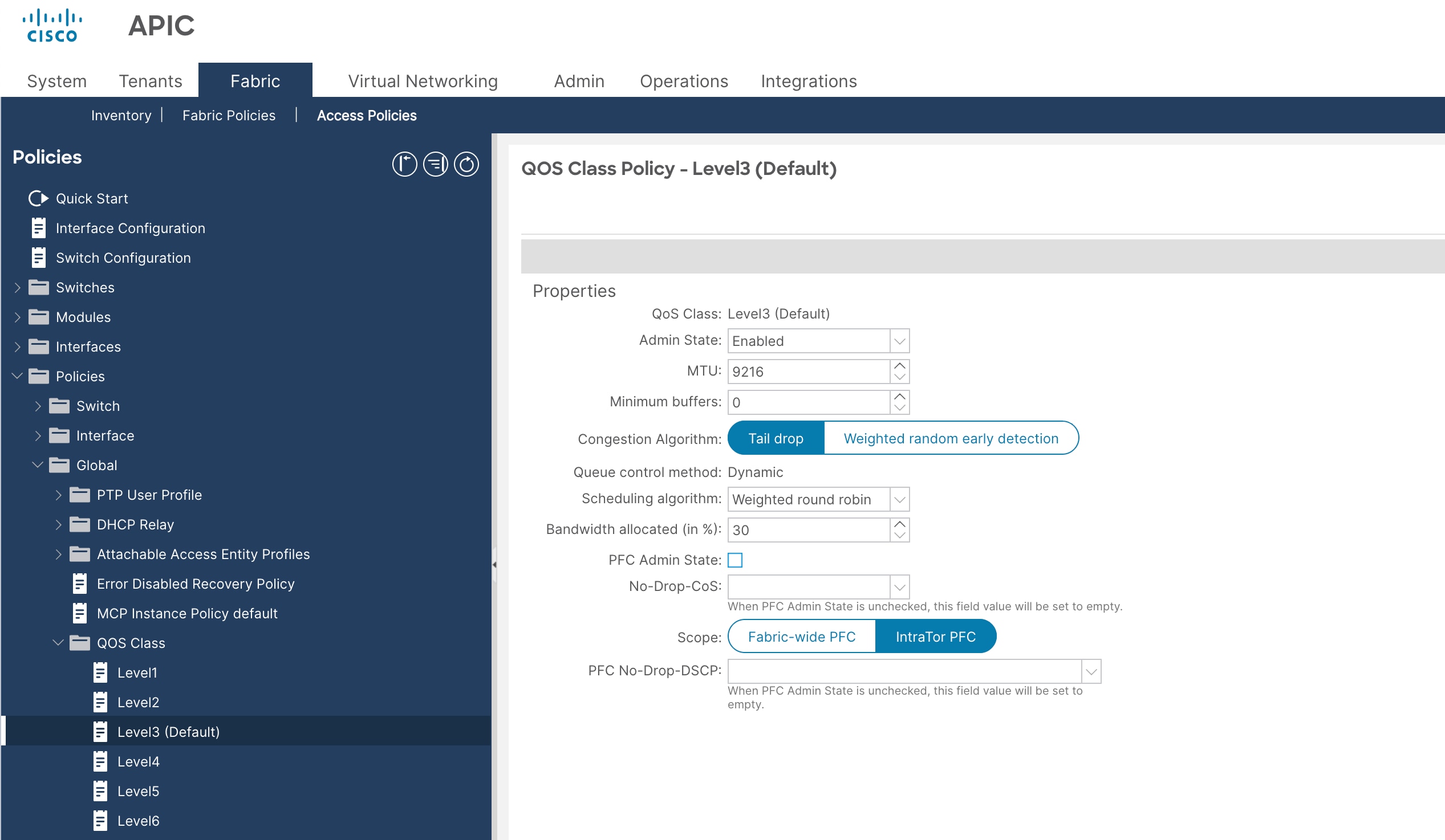
● QoS Class: Level3 (Default)
● Scheduling algorithm: Weighted round robin (default configuration)
● Bandwidth allocation (in %): 30
● PFC Admin State: unchecked
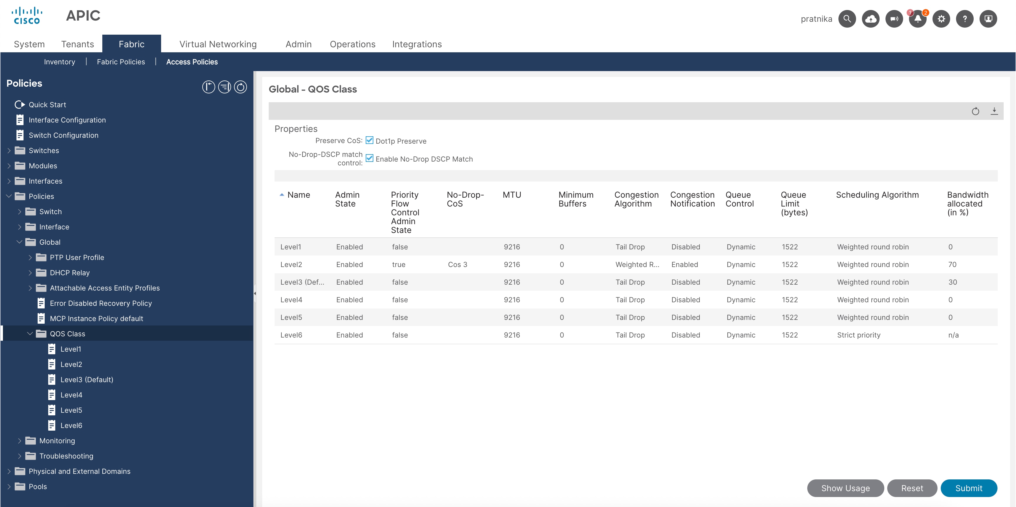
16. From the left navigation pane, expand Policies > Global > QoS Class and enable these settings:
● Preserve Cos: checked
● No-Drop-DSCP match control: checked
Configure a custom QoS policy
This document uses the custom QoS policy configuration at the EPG for Storage-External and Storage-Internal network and control plane communication (level2 for Storage-External and Storage-Internal network with DSCP 26 and level6 for control plane communication with DSCP 48).
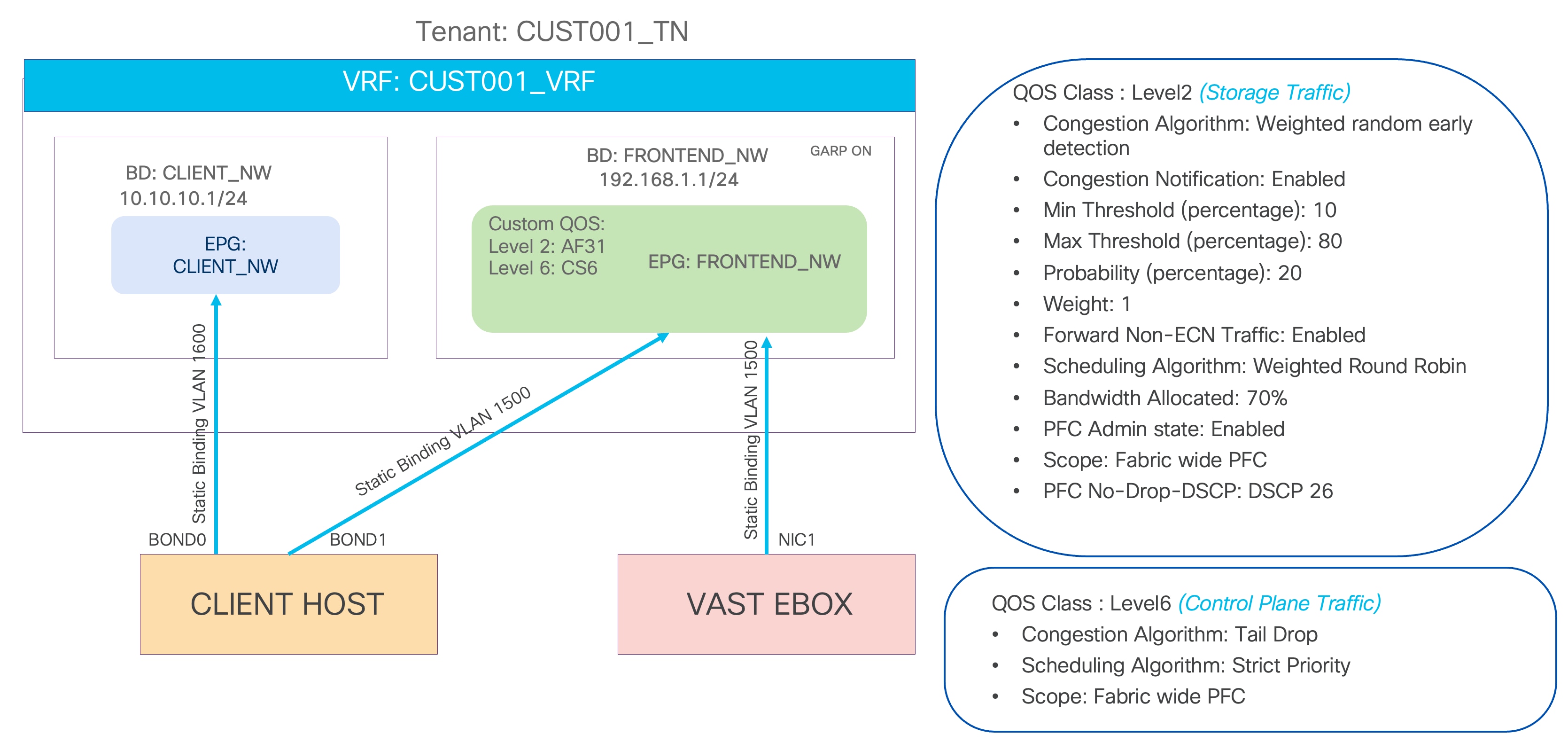
Figure 7 ACI QoS and EPG configuration example
To configure a Custom QoS policy, follow these steps:
1. From the Cisco APIC top navigation menu, select Tenants (or select an existing tenant where you want to configure EPGs, in this example CUST001_TN).
2. From the left navigation pane, expand and select Policies > Protocol > Custom QoS.
3. Right-click and select Create Custom QoS Policy to open the Create Custom QoS Policy pop-up window.
4. In the Name field, enter a name. For example, enter RoCEv2.
5. In the DSCP to priority map field, click + and configure the followings:
a. Priority. In this example, select level2 from the drop-down list for storage traffic.
b. DSCP Range From and To. In this example, specify AF31 Low Drop, which corresponds to DSCP 26 for storage traffic.
6. Click Update.
7. Repeat steps 5 and 6 for control plane communication traffic. In this example, Priority will be level6 and DSCP Range will be CS6 which corresponds to DSCP 48.
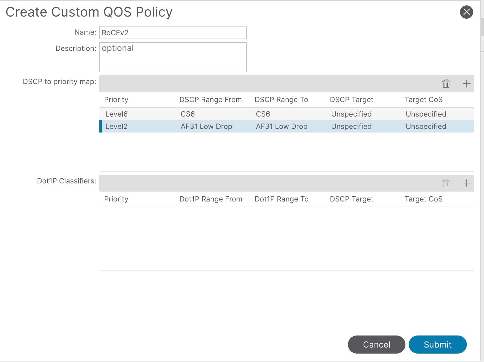
8. Click Submit.
This custom QoS policy is referred to in the next procedures.
Configure the EPGs and bridge domains
The following EPGs are created in this section:
● STORAGE-EXTERNAL bridge domain for VAST Data storage
● STORAGE-INTERNAL EPG for VAST Data storage
● Add custom QoS policy in the EPG
Configure Tenant EPGs
To configure a tenant EPG for VAST Data storage, follow these steps:
1. From the Cisco APIC top navigation menu, select Tenants > Add Tenant.
2. In the Create Tenant dialog box, enter a name. For example, enter CUST001_TN.
3. In the VRF Name field, enter the VRF name and click Finish. For example, enter CUST001_VRF.
4. Right click on Bridge Domains and click Create a Bridge Domain.
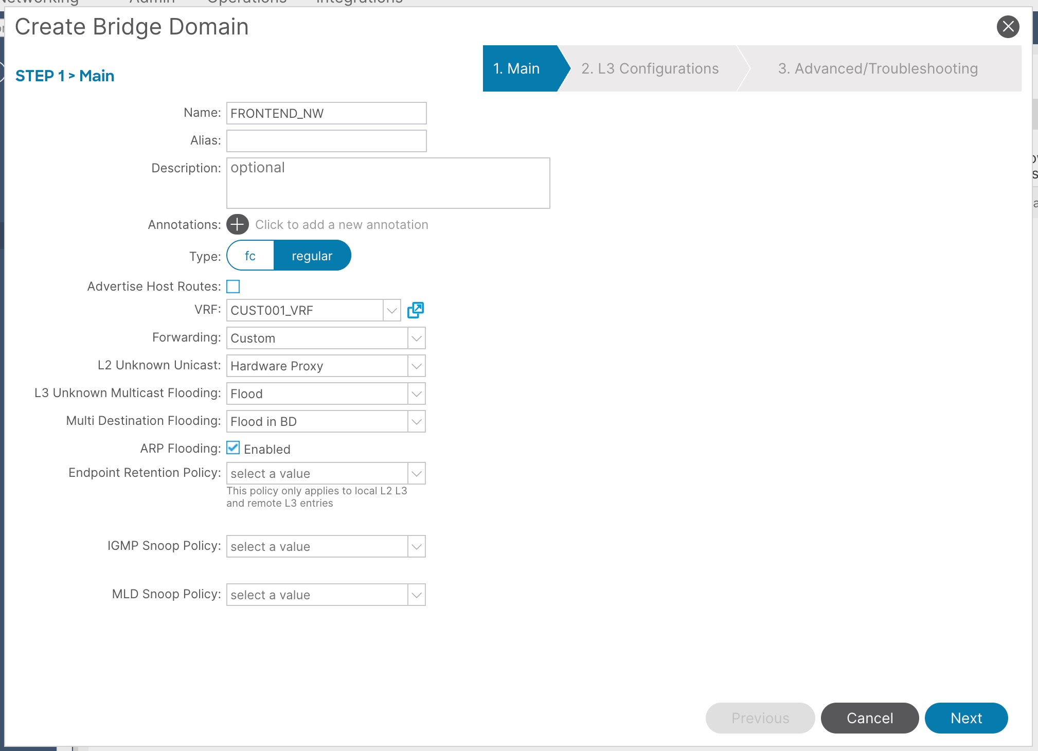
5. In the Name field, enter a name and VRF instance, then click Next. For example, enter STORAGE-EXTERNAL and CUST001_VRF.
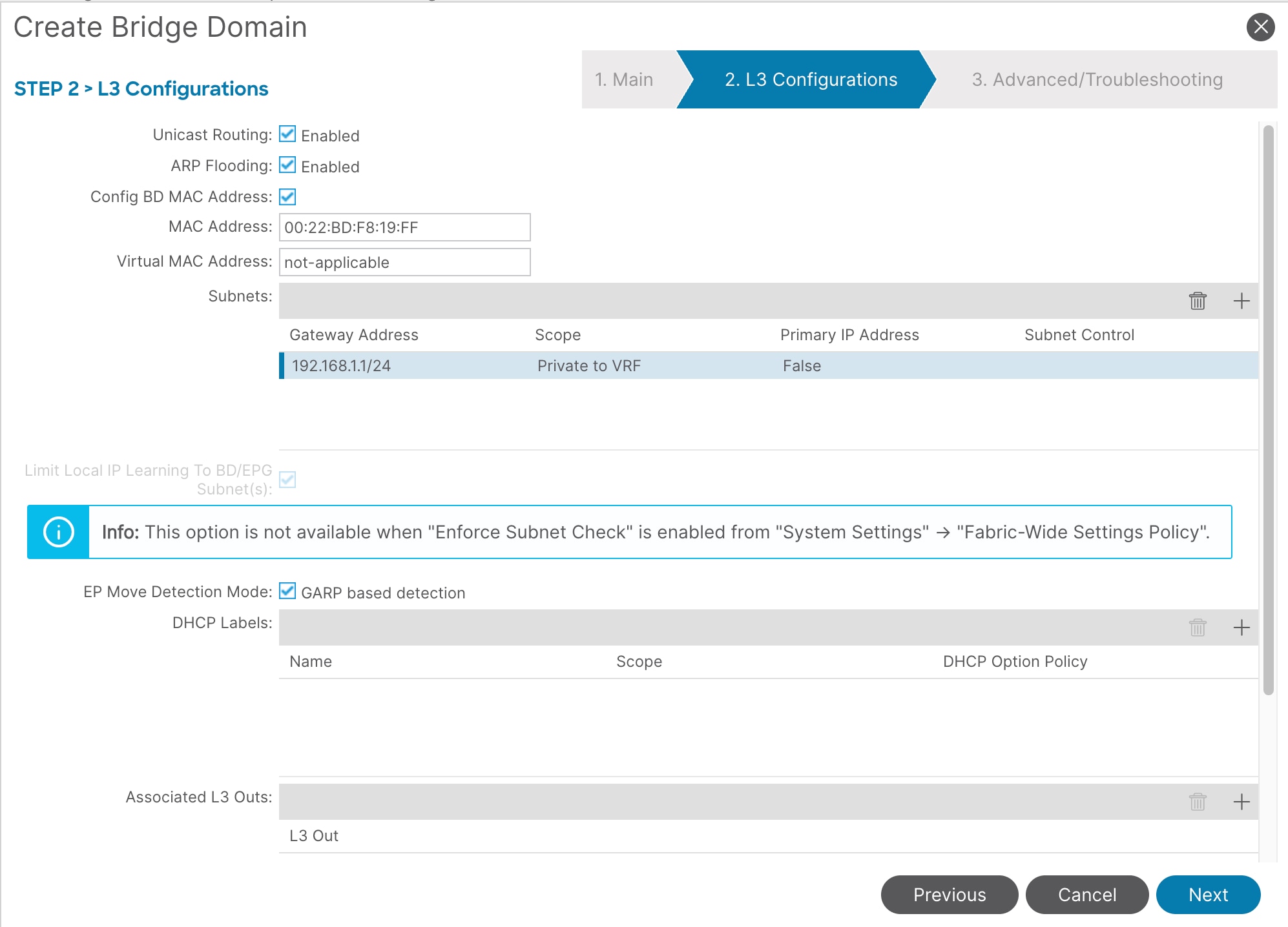
6. In the L3 configurations section, enable these settings:
a. Unicast Routing: Enabled
b. EP Move Detection Mode: GARP based detection
7. Create an anycast gateway IP address on the bridge domain, click '+' in front of Subnets.
8. In the Gateway IP field, enter the anycast gateway IP address and click Submit. In this example, enter 192.168.1.1/24.
9. To create an application profile, from the left navigation pane, right-click Application Profiles and select Create Application Profile.
10. In the Name field, enter a name and click Submit. For example, enter CUST001_AP.
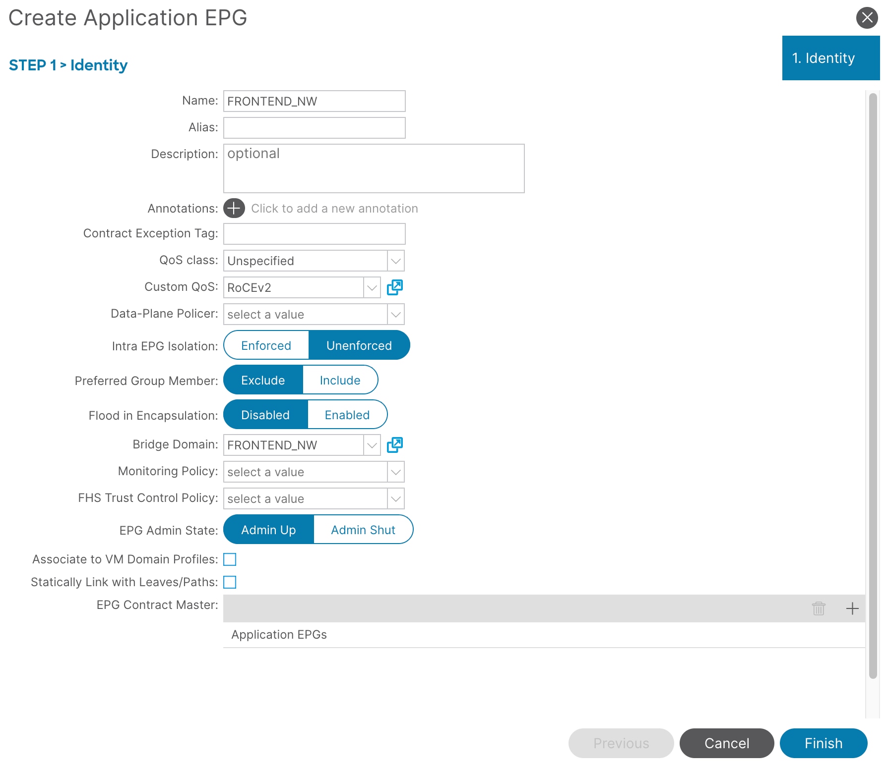
11. To create an EPG, from the left navigation pane, expand the created application profile, right-click Application EPGs, and select Create Application EPG.
12. In the Name field, enter a name. For example, enter STORAGE-EXTERNAL.
13. In the Custom QoS field, from the drop-down list, select the custom QoS policy you created. In this example, select RoCEv2.
14. In the Bridge Domain field, from the drop-down list, select the bridge domain you created. In this example, select STORAGE-EXTERNAL.
15. Click Finish.
16. From the Cisco APIC top navigation menu, navigate to ALL Tenants > CUST001_TN > Application Profiles > CUST001_AP > Application EPGs > STORAGE-EXTERNAL > Domains.
17. Right click and select Add Physical Domain Association from the drop-down list, then select the physical domain you created. In this example, select VAST_PHY_DOM.
18. Click Submit.
19. Navigate to CUST001_TN > Application Profiles > CUST001_AP > Application EPGs > STORAGE-EXTERNAL > Static Ports.
20. Right click and select Deploy Static EPG on PC, VPC, or Interface.
21. In the Path Type field, select Port. Enter the Node, Path, Port Encap, and Mode. In this example, select Node: 101, Path: 1/11, Port Encap: 1500, and Mode: Trunk.
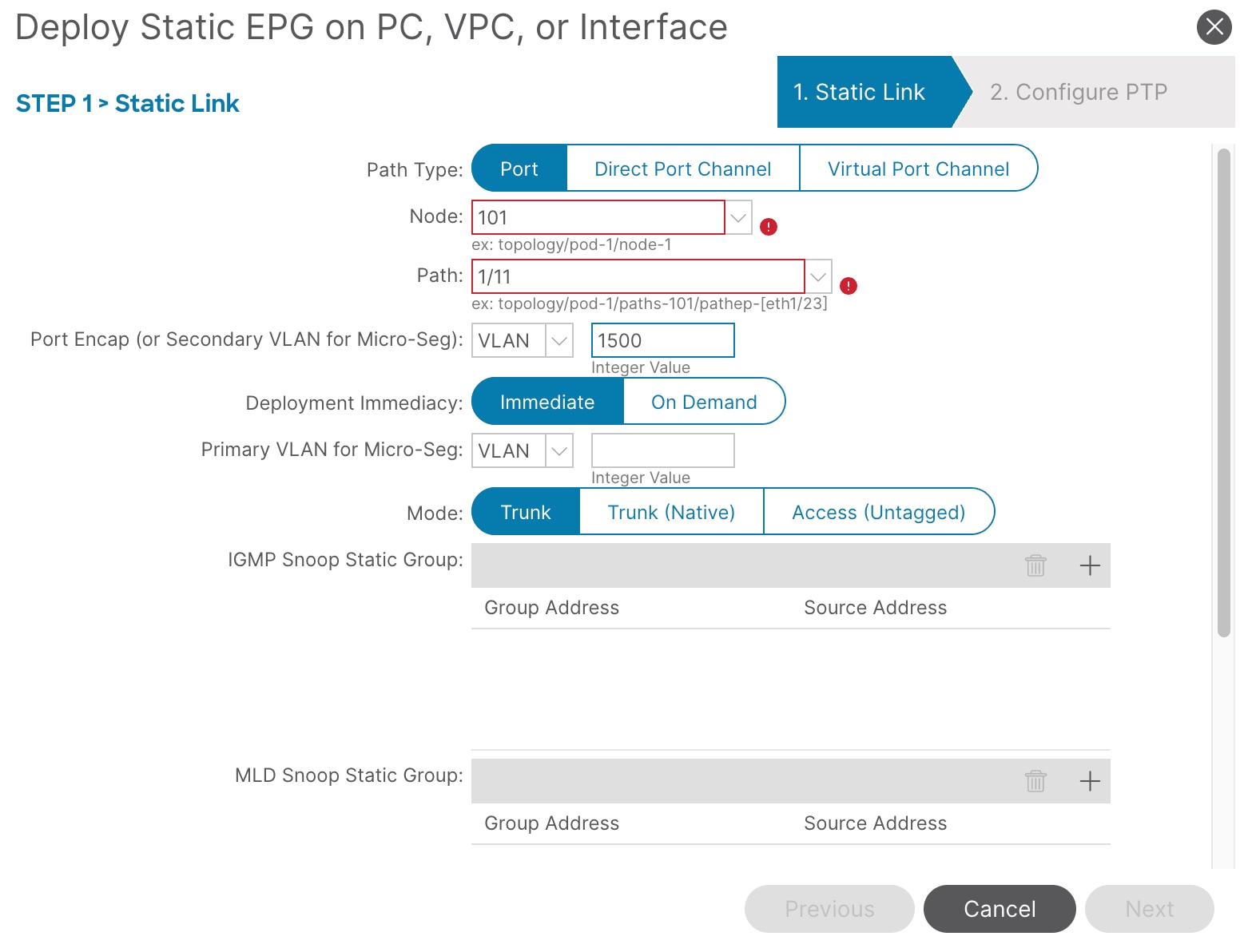
22. Click Next, then click Finish.
23. Repeat step 21 and 22 to add all interfaces that are connected to VAST Data storage servers in the cluster as well as the client host that is communicating with VAST Data storage. In this example, add Node-101/eth1/11-13 and Node-102/eth1/11-13 with vlan-1500 and mode Trunk.
24. As both the client host and VAST Data storage are part of the same EPG, contracts are not required for the communication to happen.
Note: Refer to the Cisco ACI configuration for VAST Data storage servers section above to create the Storage-Internal & Storage-Broadcast network. For example, create the STORAGE-INTERNAL bridge domain and an EPG with similar access and QoS policies as STORAGE-EXTERNAL.
● AI Infrastructure with Cisco Nexus 9000 switchesAI Infrastructure with Cisco Nexus 9000 switches
● Cisco APIC and QoSCisco APIC and QoS
● ROCE implementation over NXOS VXLAN fabricsROCE implementation over NXOS VXLAN fabrics
● VAST Data whitepapersVAST Data whitepapers
● VAST Data on Cisco UCS Data SheetVAST Data on Cisco UCS Data Sheet
| Revision |
Coverage |
Date |
| Initial version |
● Cisco ACI Release 6.1(4h)
● Cisco ACI Switch Release 16.1(4h)
|
September 22, 2025
|
| Update |
● Cisco ACI Release 6.1(4h)
● Cisco ACI Switch Release 16.1(4h)
|
February 23, 2026
|