Determining the Number and Types of Leaf Switches Required in the IP Fabric
The number and types of leaf switches required in your IP fabric depend on the number and types of endpoints in your broadcasting center.
Follow these steps to help determine how many leaf switches you need:
-
Count the number of endpoints (cameras, microphones, and so on) in your broadcasting center (for example, 360 10-Gbps endpoints and 50 40-Gbps endpoints).
-
Determine the type of leaf switches required based on the type of endpoints in your broadcasting center.
-
For 10-Gbps endpoints, use the Cisco Nexus 92160YC-X, 93108TC-EX, 93108TC-FX, 93216TC-FX2, 93180YC-FX, or 93180YC-EX leaf switches.
-
For 25-Gbps endpoints, use the Cisco Nexus 93180YC-FX, 93180YC-EX, 93240YC-FX2, or 93360YC-FX2 leaf switches.
-
For 40-Gbps endpoints, use the Cisco Nexus 9272Q, 9336C-FX2, 9364C, or 9332C leaf switches.
-
For 100-Gbps endpoints, use the Cisco Nexus 9236C, 9336C-FX2, 9364C, or 9332C leaf switches.
-
-
Determine the number of leaf switches required based on the number of endpoints and uplinks that each leaf switch supports.

Note
The uplink and downlink numbers in the following table are a recommendation. There are no technical limitations to use certain ports as uplinks or host-facing links.
Table 1. Endpoints and Uplinks Supported Per Leaf Switch Leaf Switch
Endpoint Capacity
Uplink Capacity
Cisco Nexus 9236C switch
25 x 40-Gbps endpoints
10 x 100-Gbps (1000-Gbps) uplinks
Cisco Nexus 9272Q switch
36 x 40-Gbps endpoints
36 x 40-Gbps (1440-Gbps) uplinks
Cisco Nexus 92160YC-X switch
40 x 10-Gbps endpoints
4 x 100-Gbps (400-Gbps) uplinks
Cisco Nexus 9336C-FX2 switch
25 x 40-Gbps endpoints
10 x 100-Gbps (1000-Gbps) uplinks
Cisco Nexus 9348GC-FXP switch
48 x 1-Gbps/100-Mbps endpoints
2 x 100-Gbps (200-Gbps) uplinks
Cisco Nexus 9364C switch1
Not applicable
64 x 100-Gbps (6400-Gbps) uplinks
Cisco Nexus 93108TC-EX switch
48 x 10-Gbps endpoints
6 x 100-Gbps (600-Gbps) uplinks
Cisco Nexus 93108TC-FX switch
48 x 1/10-Gbps endpoints
6 x 100-Gbps (600-Gbps) uplinks
Cisco Nexus 93180LC-EX switch
32 x 40-Gbps endpoints
4 x 100-Gbps (400-Gbps) uplinks
Cisco Nexus 93180YC-EX switch
48 x 10-Gbps endpoints
6 x 100-Gbps (600-Gbps) uplinks
Cisco Nexus 93180YC-FX switch
48 x 10/25-Gbps endpoints
6 x 100-Gbps (600-Gbps) uplinks
Cisco Nexus 93216TC-FX2 switch
96 x 1/10-Gbps endpoints
12 x 40/100-Gbps (1200-Gbps) uplinks
Cisco Nexus 93240YC-FX2 switch
48 x 10/25-Gbps endpoints
12 x 100-Gbps (1200-Gbps) uplinks
Cisco Nexus 93360YC-FX2 switch
96 x 10/25-Gbps endpoints
12 x 40/100-Gbps (1200-Gbps) uplinks
1 The Cisco Nexus 9364C switch does not support breakout. For example:
-
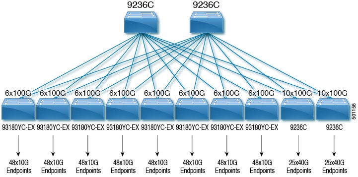
For 360 10-Gbps endpoints, you need eight Cisco Nexus 93180YC-EX leaf switches because each switch can support up to 48 10-Gbps endpoints.
-
For 50 40-Gbps endpoints, you need two Cisco Nexus 9236C leaf switches because each switch can support up to 25 40-Gbps endpoints.
-
-
Make sure that the uplink bandwidth (toward the spine switch) is greater than or equal to the downstream bandwidth (toward the endpoints).
-
Use this equation to determine the uplink bandwidth:
Uplink Capacity per Leaf Switch x Number of Leaf Switches = Uplink BandwidthFor example:
600 Gbps (uplink capacity for each Cisco Nexus 93180YC-EX switch) x eight Cisco Nexus 93180YC-EX leaf switches = 4800-Gbps uplink bandwidth.
1000 Gbps (uplink capacity for each Cisco Nexus 9236C switch) x two Cisco Nexus 9236C leaf switches = 2000-Gbps uplink bandwidth.
4800-Gbps uplink bandwidth (for eight Cisco Nexus 93180YC-EX leaf switches) + 2000-Gbps uplink bandwidth (for two Cisco Nexus 9236C leaf switches) = 6800-Gbps total uplink bandwidth.
-
Use this equation to determine the downstream bandwidth:
Endpoint Capacity per Leaf Switch x Number of Leaf Switches = Downstream BandwidthFor example:
48 x 10 Gbps (480-Gbps endpoint capacity) for each Cisco Nexus 93180YC-EX leaf switch x eight leaf switches = 3840-Gbps downstream bandwidth.
25 x 40 Gbps (1000-Gbps endpoint capacity) for each Cisco Nexus 9236C leaf switch x two leaf switches = 2000-Gbps downstream bandwidth.
3840-Gbps downstream bandwidth (for eight Cisco Nexus 93180YC-EX leaf switches) + 2000-Gbps downstream bandwidth (for two Cisco Nexus 9236C leaf switches) = 5840-Gbps total downstream bandwidth.
-
-
If the total uplink bandwidth is greater than or equal to the total downstream bandwidth, your topology is valid. You can now determine the number of achievable flows. If the uplink bandwidth is less than the downstream bandwidth, rework your topology until the upstream bandwidth is equal to or greater than the downstream bandwidth.
The NBM flows can't utilize all the expected bandwidth as the PIM bidir RP configuration utilizes the NBM bandwidth available. To increase the NBM bandwidth, remove the PIM bidir RP configuration.
The following topology uses the examples in this section:
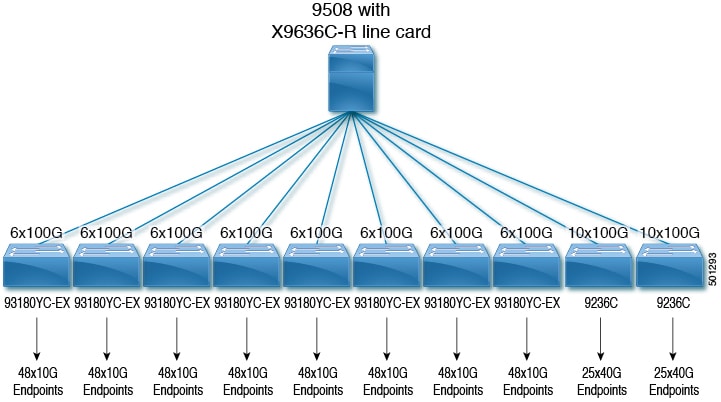
The following diagram shows an example topology with a Cisco Nexus 9508 spine switch and an N9K-X9636C-R line card:
 Feedback