Configuring PIM

This chapter describes how to configure the Protocol Independent Multicast (PIM) and bidirectional PIM (PIM-Bidir) features on Cisco NX-OS switches in your IPv4 networks.


Note


PIM Any Source Multicast (ASM) and Source-Specific Multicast (SSM) are unidirectional. PIM-Bidir is an enhanced form of PIM that allows bidirectional data flow. PIM-Bidir eliminates any source-specific state and allows trees to scale to an arbitrary number of sources. The differences between other PIM modes and PIM-Bidir are explained in the section Information about PIM-Bidir. Configuration of PIM and PIM-Bidir are similar. Textual notes and procedures indicate any configuration differences.

This chapter includes the following sections:

Information about PIM

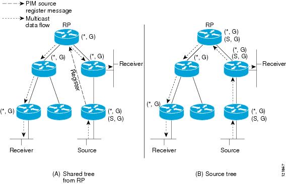
PIM, which is used between multicast-capable routers, advertises group membership across a routing domain by constructing multicast distribution trees. PIM builds shared distribution trees on which packets from multiple sources are forwarded, as well as source distribution trees on which packets from a single source are forwarded. For more information about multicast, see the Information About Multicast section.

Cisco NX-OS supports PIM sparse mode for IPv4 networks (PIM). (In PIM sparse mode, multicast traffic is sent only to locations of the network that specifically request it.) You can configure PIM to run simultaneously on a router. You can use PIM global parameters to configure rendezvous points (RPs), message packet filtering, and statistics. You can use PIM interface parameters to enable multicast, identify PIM borders, set the PIM hello message interval, and set the designated router (DR) priority. For more information, see the Configuring PIM Sparse Mode section.


Note


Cisco NX-OS does not support PIM dense mode.

In Cisco NX-OS, multicast is enabled only after you enable the PIM feature on each router and then enable PIM sparse mode on each interface that you want to participate in multicast. You can configure PIM for an IPv4 network. In an IPv4 network, if you have not already enabled IGMP on the router, PIM enables it automatically. For information about configuring IGMP, see Configuring IGMP .

You use the PIM global configuration parameters to configure the range of multicast group addresses to be handled by each of the two distribution modes:

  • Any Source Multicast (ASM) provides discovery of multicast sources. It builds a shared tree between sources and receivers of a multicast group and supports switching over to a source tree when a new receiver is added to a group. ASM mode requires that you configure an RP.

  • Source-Specific Multicast (SSM) builds a source tree that originates at the designated router on the LAN segment that receives a request to join a multicast source. SSM mode does not require you to configure RPs. Source discovery must be accomplished through other means.

You can combine the modes to cover different ranges of group addresses. For more information, see the Configuring PIM section. For more information about PIM sparse mode and shared distribution trees used by the ASM mode, see RFC 4601.

For more information about PIM in SSM mode, see RFC 3569.

For more information about PIM-Bidir, see RFC5015.


Note


Multicast equal-cost multipathing (ECMP) is on by default in the Cisco NX-OS for the Cisco Nexus 3548 Switch; you cannot turn ECMP off. If multiple paths exist for a prefix, PIM selects the path with the lowest administrative distance in the routing table. Cisco NX-OS supports up to 16 paths to a destination.

Hello Messages

The PIM process begins when the router establishes PIM neighbor adjacencies by sending PIM hello messages to the multicast address 224.0.0.13. Hello messages are sent periodically at the interval of 30 seconds. When all neighbors have replied, then the PIM software chooses the router with the highest priority in each LAN segment as the designated router (DR). The DR priority is based on a DR priority value in the PIM hello message. If the DR priority value is not supplied by all routers, or the priorities match, the highest IP address is used to elect the DR.


Caution


If you change the PIM hello interval to a lower value (less than 10 seconds, or depending on your network environment), it may cause loss in multicast traffic.


The hello message also contains a hold-time value, which is typically 3.5 times the hello interval. If this hold time expires without a subsequent hello message from its neighbor, the switch detects a PIM failure on that link.

For added security, you can configure an MD5 hash value that the PIM software uses to authenticate PIM hello messages with PIM neighbors.


Note


If PIM is disabled on the switch, the IGMP snooping software processes the PIM hello messages.


For information about configuring hello message authentication, see the Configuring PIM Sparse Mode section.

Join-Prune Messages

When the DR receives an IGMP membership report message from a receiver for a new group or source, the DR creates a tree to connect the receiver to the source by sending a PIM join message out the interface toward the rendezvous point (ASM mode) or source (SSM mode).The rendezvous point (RP) is the root of a shared tree, which is used by all sources and hosts in the PIM domain in the ASM mode. SSM does not use an RP but builds a shortest path tree (SPT) that is the lowest cost path between the source and the receiver. In PIM-Bidir mode, the Designated Forwarder (DF) is in charge of sending the PIM join message instead of the DR.

When the DR determines that the last host has left a group or source, it sends a PIM prune message to remove the path from the distribution tree. The routers forward the join or prune action hop by hop up the multicast distribution tree to create (join) or tear down (prune) the path.


Note


PIM-Bidir uses rendezvous points (RPs) and form bidirectional trees as explained in the section Information about PIM-Bidir.


Note


In this publication, the terms PIM join message and PIM prune message are used to simplify the action taken when referring to the PIM join-prune message with only a join or prune action.


Join-prune messages are sent as quickly as possible by the software. You can filter the join-prune messages by defining a routing policy. For information about configuring the join-prune message policy, see the Configuring PIM Sparse Mode section.

You can prebuild the SPT for all known (S, G) in the routing table by triggering PIM joins upstream. To prebuild the SPT for all known (S, G)s in the routing table by triggering PIM joins upstream, even in the absence of any receivers, use the ip pim pre-build-spt command. By default, PIM (S, G) joins are triggered upstream only if the OIF-list for the (S, G) is not empty.

State Refreshes

PIM requires that multicast entries are refreshed within a 3.5-minute timeout interval. The state refresh ensures that traffic is delivered only to active listeners, and it keeps routers from using unnecessary resources.

To maintain the PIM state, the last-hop DR sends join-prune messages once per minute. State creation applies to both (*, G) and (S, G) states as follows:

  • (*, G) state creation example—An IGMP (*, G) report triggers the DR to send a (*, G) PIM join message toward the RP.

  • (S, G) state creation example—An IGMP (S, G) report triggers the DR to send an (S, G) PIM join message toward the source.

If the state is not refreshed, the PIM software tears down the distribution tree by removing the forwarding paths in the multicast outgoing interface list of the upstream routers.

Rendezvous Points

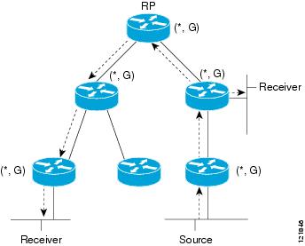
A rendezvous point (RP) is a router that you select in a multicast network domain that acts as a shared root for a multicast shared tree. You can configure as many RPs as you like, and you can configure them to cover different group ranges.

Static RP

You can statically configure an RP for a multicast group range. You must configure the address of the RP on every router in the domain.

You can define static RPs for the following reasons:

  • To configure routers with the Anycast-RP address

  • To manually configure an RP on a switch

For information about configuring static RPs, see the Configuring Static RPs section.

BSRs

The bootstrap router (BSR) ensures that all routers in the PIM domain have the same RP cache as the BSR. You can configure the BSR to help you select an RP set from BSR candidate RPs. The function of the BSR is to broadcast the RP set to all routers in the domain. You select one or more candidate BSRs to manage the RPs in the domain. Only one candidate BSR is elected as the BSR for the domain.


Caution


Do not configure both Auto-RP and BSR protocols in the same network.


Figure 1 shows where the BSR mechanism, router A, the software-elected BSR, sends BSR messages out all enabled interfaces (shown by the solid lines in the figure). The messages, which contain the RP set, are flooded hop by hop to all routers in the network. Routers B and C are candidate RPs that send their candidate-RP advertisements directly to the elected BSR (shown by the dashed lines in the figure).

The elected BSR receives candidate-RP messages from all the candidate RPs in the domain. The bootstrap message sent by the BSR includes information about all of the candidate RPs. Each router uses a common algorithm to select the same RP address for a given multicast group.

Figure 1. BSR Mechanism

In the RP selection process, the RP address with the best priority is determined by the software. If the priorities match for two or more RP addresses, the software may use the RP hash in the selection process. Only one RP address is assigned to a group.

By default, routers are not enabled to listen or forward BSR messages. You must enable the BSR listening and forwarding feature so that the BSR mechanism can dynamically inform all routers in the PIM domain of the RP set assigned to multicast group ranges.


Note


The BSR mechanism is a nonproprietary method of defining RPs that can be used with third-party routers.


For information about configuring BSRs and candidate RPs, see the Configuring BSRs section.

Auto-RP

Auto-RP is a Cisco protocol that was introduced prior to the Internet standard bootstrap router mechanism. You configure Auto-RP by selecting candidate mapping agents and RPs. Candidate RPs send their supported group range in RP-Announce messages to the Cisco RP-Announce multicast group 224.0.1.39. An Auto-RP mapping agent listens for RP-Announce messages from candidate RPs and forms a Group-to-RP mapping table. The mapping agent multicasts the Group-to-RP mapping table in RP-Discovery messages to the Cisco RP-Discovery multicast group 224.0.1.40.


Caution


Do not configure both Auto-RP and BSR protocols in the same network.


Figure 2 shows the Auto-RP mechanism. Periodically, the RP mapping agent multicasts the RP information that it receives to the Cisco-RP-Discovery group 224.0.1.40 (shown by the solid lines in the figure).

Figure 2. Auto-RP Mechanism

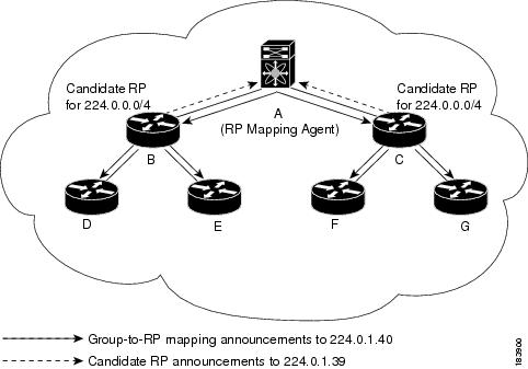
By default, routers are not enabled to listen or forward Auto-RP messages. You must enable the Auto-RP listening and forwarding feature so that the Auto-RP mechanism can dynamically inform routers in the PIM domain of the Group-to-RP mapping.

For information about configuring Auto-RP, see the Configuring Auto-RP section.

Anycast-RP

Anycast-RP has two implementations: one uses Multicast Source Discovery Protocol (MSDP) and the other is based on RFC 4610. This section describes how to configure PIM Anycast-RP.

You can use PIM Anycast-RP to assign a group of routers, called the Anycast-RP set, to a single RP address that is configured on multiple routers. The set of routers that you configure as Anycast-RPs is called the Anycast-RP set. This method is the only RP method that supports more than one RP per multicast group, which allows you to load balance across all RPs in the set. The Anycast RP supports all multicast groups.

PIM register messages are sent to the closest RP and PIM join-prune messages are sent in the direction of the closest RP as determined by the unicast routing protocols. If one of the RPs goes down, unicast routing ensures these message will be sent in the direction of the next-closest RP.

For more information about PIM Anycast-RP, see RFC 4610.

For information about configuring Anycast-RPs, see the Configuring a PIM Anycast-RP Set section.

PIM Register Messages

PIM register messages are unicast to the RP by designated routers (DRs) that are directly connected to multicast sources. The PIM register message has the following functions:

  • To notify the RP that a source is actively sending to a multicast group.

  • To deliver multicast packets sent by the source to the RP for delivery down the shared tree.

The DR continues to send PIM register messages to the RP until it receives a Register-Stop message from the RP. The RP sends a Register-Stop message in either of the following cases:

  • The RP has no receivers for the multicast group being transmitted.

  • The RP has joined the SPT to the source but has not started receiving traffic from the source.

You can use the ip pim register-source command to configure the IP source address of register messages when the IP source address of a register message is not a uniquely routed address to which the RP can send packets. This situation might occur if the source address is filtered so that the packets sent to it are not forwarded or if the source address is not unique to the network. In these cases, the replies sent from the RP to the source address fails to reach the DR, resulting in Protocol Independent Multicast sparse mode (PIM-SM) protocol failures.

The following example shows how to configure the IP source address of the register message to the loopback 3 interface of a DR:

switch # configuration terminal
switch(config)# vrf context Enterprise
switch(config-vrf)# ip pim register-source ethernet 2/3
switch(config-vrf)#

Note


In Cisco NX-OS, PIM register messages are rate limited to avoid overwhelming the RP.


You can filter PIM register messages by defining a routing policy. For information about configuring the PIM register message policy, see the Configuring Message Filtering section.

Designated Routers

In PIM ASM and SSM modes, the software chooses a designated router (DR) from the routers on each network segment. The DR is responsible for forwarding multicast data for specified groups and sources on that segment.

The DR for each LAN segment is determined as described in the Hello Messages section.

In ASM mode, the DR is responsible for unicasting PIM register packets to the RP. When a DR receives an IGMP membership report from a directly connected receiver, the shortest path is formed to the RP, which may or may not go through the DR. The result is a shared tree that connects all sources transmitting on the same multicast group to all receivers of that group.

In SSM mode, the DR triggers (*, G) or (S, G) PIM join messages toward the source. The path from the receiver to the source is determined hop by hop. The source must be known to the receiver or the DR.

For information about configuring the DR priority, see the Configuring PIM Sparse Mode section.

Multicast Flow Path Visibility

Beginning with Cisco NX-OS Release 10.2(2)F, Multicast Flow Path Visualization (FPV) feature is supported on Cisco Nexus 3548-XL platform switches. This feature enables you to export all multicast states in a Cisco Nexus 3548-XL platform switch. This helps to have a complete and reliable traceability of the flow path from the source to a receiver.

To enable Multicast Flow Path Data Export on Cisco Nexus 3548-XL platform switches, use the multicast flow-path export command.

This feature supports the following:

  • Flow Path Visualization (FPV).

  • Export flow statistics and states for failure detection.

  • Root cause analysis on the switches along the flow path. This is done by running the appropriate debug commands.

Guidelines and Limitations for Multicast Flow Path Visibility

Multicast flow path visibility feature has the following guidelines and limitations:

  • Beginning with Cisco NX-OS 10.2(2)F, the multicast flow path visibility feature is supported on Cisco Nexus 3548-XL platform switches.

  • This featue does not support the following:

    • PIM Bidir

    • VPC

    • Route leak

  • Only L3 routes including (*, G)s, (S, G)s can be exported.

  • Supports multicast ASM and SSM.

  • Support both L3 routed ports (any type) and SVI L2 fanout.

  • Supports interfaces such as L3 physical ports, L2 physical ports, portchannel and portchannel sub-interfaces, and sub-interfaces.

Administratively Scoped IP Multicast

The administratively scoped IP multicast method allows you to set boundaries on the delivery of multicast data. For more information, see RFC 2365 .

You can configure an interface as a PIM boundary so that PIM messages are not sent out that interface. For information about configuring the domain border parameter, see the Configuring Message Filtering section.

You can use the Auto-RP scope parameter to set a time-to-live (TTL) value. For more information, see the Configuring Auto-RP section.

Virtualization Support

You can define multiple virtual routing and forwarding (VRF) instances. For each VRF, independent multicast system resources are maintained, including the MRIB.

You can use the PIM show commands with a VRF argument to provide a context for the information displayed. The default VRF is used if no VRF argument is supplied.

For information about configuring VRFs, see the Cisco Nexus 3548 Switch NX-OS Unicast Routing Configuration Guide.

Information about PIM-Bidir

PIM-Bidir

The bidirectional mode for PIM (PIM-Bidir) is an enhancement of the PIM protocol that was designed for efficient many-to-many communications within an individual PIM domain. Multicast groups in bidirectional mode can scale to an arbitrary number of sources with only a minimal amount of additional overhead.

The shared trees that are created in PIM sparse mode are unidirectional. This means that a source tree must be created to bring the data stream to the root of the shared tree, or rendezvous point (RP), and then it can be forwarded down the branches to the receivers. Source data cannot flow up the shared tree toward the RP because this would be considered a bidirectional shared tree.

PIM-Bidir is derived from the mechanisms of PIM sparse mode (PIM-SM) and shares many of the shared tree operations. PIM-Bidir also has unconditional forwarding of source traffic toward the RP upstream on the shared tree, but PIM-Bidir differs in that it has no registering process for sources like those used in PIM-SM. These modifications in PIM-Bidir are necessary and sufficient to allow forwarding of traffic in all devices solely based on the (*, G) multicast routing entries. This feature eliminates any source-specific state and allows scaling capability to an arbitrary number of sources.

Bidirectional Shared Tree

In bidirectional mode, traffic is routed only along a bidirectional shared tree that is rooted at the rendezvous point (RP) for the group. In PIM-Bidir, the IP address of the RP acts as the key to having all devices establish a loop-free spanning tree topology rooted in that IP address. This IP address need not be a device, but can be any unassigned IP address on a network that is reachable throughout the PIM domain. This technique is the preferred configuration method for establishing a redundant RP configuration for PIM-Bidir.

Membership in a bidirectional group is signaled by way of explicit Join messages. Traffic from sources is unconditionally sent up the shared tree toward the RP and passed down the tree toward the receivers on each branch of the tree.

Figure 3 and Figure 4 show the difference in state created per device for a unidirectional shared tree and source tree as compared to a bidirectional shared tree.

Figure 3. Unidirectional Shared Tree and Source Tree
Figure 4. Bidirectional Shared Tree

For packets that are forwarded downstream from the RP toward receivers, there are no fundamental differences between PIM-Bidir and PIM sparse mode (PIM-SM). PIM-Bidir deviates substantially from PIM-SM for traffic that is passed from sources upstream toward the RP.

PIM-SM cannot forward traffic in the upstream direction of a tree because it accepts traffic from only one Reverse Path Forwarding (RPF) interface. This interface (for the shared tree) points toward the RP, thus allowing only downstream traffic flow. Upstream traffic is first encapsulated into unicast register messages, which are passed from the designated router (DR) of the source toward the RP. Second, the RP joins a source path tree (SPT) that is rooted at the source. Therefore, in PIM-SM, traffic from sources destined for the RP does not flow upstream in the shared tree, but downstream along the SPT of the source until it reaches the RP. From the RP, traffic flows along the shared tree toward all receivers.

In PIM-Bidir, the packet-forwarding rules have been improved over PIM-SM, allowing traffic to be passed up the shared tree toward the RP. To avoid multicast packet looping, PIM-Bidir introduces a new mechanism called designated forwarder (DF) election, which establishes a loop-free Rendezvous Point Tree (RPT) rooted at the RP.

DF Election

On every network segment and point-to-point link, all PIM devices participate in a procedure called designated forwarder (DF) election. The procedure selects one device as the DF for each rendezvous point (RP) of bidirectional groups. The DF is responsible for forwarding multicast packets received on that network.

The DF election is based on unicast routing metrics. The device with the most preferred unicast routing metric to the RP becomes the DF. Use of this method ensures that only one copy of every packet will be sent to the RP, even if there are parallel equal-cost paths to the RP.

A DF is selected for every RP of bidirectional groups. As a result, multiple devices may be elected as DF on any network segment, one for each RP. Any particular device can be elected as DF on more than one interface.

Bidirectional Group Tree Building

The procedure for joining the shared tree of a bidirectional group is nearly identical to that used in PIM Sparse Mode (PIM-SM). One main difference is that, for bidirectional groups, the role of the designated router (DR) is assumed by the designated forwarder (DF) for the rendezvous point (RP).

On a network that has local receivers, only the device elected as the DF populates the outgoing interface list (oiflist) upon receiving Internet Group Management Protocol (IGMP) Join messages, and sends (*, G) Join and Leave messages upstream toward the RP. When a downstream device wishes to join the shared tree, the reverse path forwarding (RPF) neighbor in the PIM Join and Leave messages is always the DF elected for the interface that leads to the RP.

When a device receives a Join or Leave message, and the device is not the DF for the receiving interface, the message is ignored. Otherwise, the device updates the shared tree in the same way as in sparse mode.

In a network where all devices support bidirectional shared trees, (S, G) Join and Leave messages are ignored. There is also no need to send PIM assert messages because the DF election procedure eliminates parallel downstream paths from any RP. An RP never joins a path back to the source, nor will it send any register stops.

Packet Forwarding

A device creates (*, G) entries only for bidirectional groups. The outgoing interface list (oiflist) of a (*, G) entry includes all the interfaces for which the device has been elected designated forwarder (DF) and that have received either an Internet Group Management protocol (IGMP) or Protocol Independent Multicast (PIM) Join message. If a device is located on a sender-only branch, it will also create a (*, G) state, but the oiflist will include only the RPF interface, unless the RP address belongs to a local interface of the router. In that case, the oiflist will be empty.

If a packet is received from the Reverse Path Forwarding (RPF) interface toward the rendezvous point (RP,) the packet is forwarded downstream according to the oiflist of the (*, G) entry. Otherwise, only the device that is the DF for the receiving interface forwards the packet upstream toward the RP; all other devices must discard the packet.

Guidelines and Limitations for PIM

PIM has the following guidelines and limitations:

  • Cisco NX-OS PIM does not interoperate with any version of PIM dense mode or PIM sparse mode version 1.

  • Cisco Nexus 3500 Series switches do not support PIM adjacency with a vPC leg or with a router behind a vPC.

  • Do not configure both Auto-RP and BSR protocols in the same network.

  • Configure candidate RP intervals to a minimum of 15 seconds.

  • If a switch is configured with a BSR policy that should prevent it from being elected as the BSR, the switch ignores the policy. This behavior results in the following undesirable conditions:

    • If a switch receives a BSM that is permitted by the policy, the switch, which incorrectly elected itself as the BSR, drops that BSM so that routers downstream fail to receive it. Downstream switches correctly filter the BSM from the incorrect BSR so that they do not receive RP information.

    • A BSM received by a BSR from a different switch sends a new BSM but ensures that downstream switches do not receive the correct BSM.

  • OpenFlow is supported on the N3K-C3548-10GX platforms.

  • The patchability feature is not supported on Cisco Nexus 3500 Series platforms.

  • You must use the ip pim sg-expiry-timer infinity command to increase the number of supported PIM multicast routes beyond 8000.

  • When the ACL log is configured matching a multicast stream where the flow is started, the corresponding S, G is not created because the ACL log consumes the packet. You must disable the log option to create the S, G route entry.

  • RPF failure will not happen for *, G or S, G if RPF interface is SVI. In case of SVI as RPF, the match of entry in hardware happens based on VLAN, S, G as key. So, traffic on different VLAN does not hit and get punted to CPU as RPF failure.

  • The ip pim spt-threshold infinity group-list and ip pim use-shared-tree-only group-list commands are supported for standalone (non-vPC) Last Hop Router (LHR) configurations. Beginning with Cisco NX-OS Release 9.3(10), the ip pim spt-threshold infinity group-list and ip pim use-shared-tree-only group-list commands are also supported for virtual port channels (vPC) on the Cisco Nexus 3548 switches.

  • The ip pim spt-threshold infinity group-list and ip pim use-shared-tree-only group-list commands are supported for standalone Cisco Nexus 3548 switch. Beginning with Cisco NX-OS Release 10.2(3), the ip pim spt-threshold infinity group-list and ip pim use-shared-tree-only group-list commands are also supported for virtual port channels (vPC) on the Cisco Nexus 3548 switches.

  • Configuring a secondary IP address as an RP address is not supported.

  • PIM must be configured on all L3 interfaces between sources, receivers, and rendezvous points (RPs).

  • Beginning with Cisco NX-OS Release 10.6(1)F, the ip pim spt-switch-graceful command is enabled by default. To disable the command, use no ip pim spt-switch-graceful command. This feature minimizes packet loss by allowing a graceful switchover from the shared tree to the shortest path tree (SPT) where the shared tree is used until the shortest path tree (SPT) is fully established and verified by receiving the first data packet.

    • In the earlier releases, this command is not enabled by default.

    • This feature is not supported for TRM VRF.

    • This feature is not supported for SVI as RPF.

    • This feature is not supported on VPC.

Guidelines and Limitations for PIM-Bidir

There are some limitations in the use of PIM-Bidir on the Cisco Nexus 3548 Switch. In particular, due to internal implementation, once a group range has been configured as Bidir for one VRF, the group-range may not be used again for other VRFs. For example, if the group-range 225.1.0.0/16 has been configured as Bidir in the default VRF, no group or part of this group-range can be re-used (as ASM, Bidir, or SSM) in a different VRF.

Default Settings for PIM

Table 1 lists the default settings for PIM parameters.

Table 1. Default PIM Parameters

Parameters

Default

Use shared trees only

Disabled

Flush routes on restart

Disabled

Log Neighbor changes

Disabled

Auto-RP message action

Disabled

BSR message action

Disabled

SSM multicast group range or policy

232.0.0.0/8 for IPv4

PIM sparse mode

Disabled

Designated router priority

0

Hello authentication mode

Disabled

Domain border

Disabled

RP address policy

No message filtering

PIM register message policy

No message filtering

BSR candidate RP policy

No message filtering

BSR policy

No message filtering

Auto-RP mapping agent policy

No message filtering

Auto-RP RP candidate policy

No message filtering

Join-prune policy

No message filtering

Neighbor adjacency policy

Become adjacent with all PIM neighbors

Configuring PIM

You can configure PIM for each interface.


Note


Cisco NX-OS supports PIM sparse mode version 2. In this publication, “PIM” refers to PIM sparse mode version 2.


You can configure separate ranges of addresses in the PIM domain using the multicast distribution modes described in Table below.

Table 2. PIM Multicast Distribution Modes

Multicast Distribution Mode

Requires RP Configuration

Description

ASM

Yes

Any source multicast

Bidir

Yes

Bidirectional shared trees

SSM

No

Source-specific multicast

RPF routes for multicast

No

RPF routes for multicast

To configure PIM, follow these steps:

Procedure


Step 1

From the multicast distribution modes described in Table 2 , select the range of multicast groups that you want to configure in each mode.

Step 2

Enable the PIM or PIM6 features. See the Enabling the PIM Features section.

Step 3

Configure PIM sparse mode on each interface that you want to participate in a PIM domain. See the Configuring PIM Sparse Mode section.

Step 4

Follow the configuration steps for the multicast distribution modes that you selected in Step 1 as follows:

Step 5

If you are configuring message filtering. See the Configuring Message Filtering section.


Enabling the PIM Feature

Before you can access the PIM commands, you must enable the PIM feature.

Before you begin

Ensure that you have installed the LAN Base Services license.

Procedure

  Command or Action Purpose

Step 1

configure terminal

Example:

switch# configure terminal
switch(config)#

Enters configuration mode.

Step 2

feature pim

Example:

switch(config)# feature pim

Enables PIM. By default, PIM is disabled.

Step 3

(Optional) show running-configuration pim

Example:

switch(config)# show running-configuration pim
(Optional)

Shows the running-configuration information for PIM, including the feature command.

Step 4

(Optional) copy running-config startup-config

Example:

switch(config)# copy running-config startup-config
(Optional)

Saves configuration changes.

Configuring PIM Sparse Mode

You configure PIM sparse mode on every switch interface that you want to participate in a sparse mode domain.


Note


For information about configuring multicast route maps, see the Configuring Route Maps to Control RP Information Distribution section.


Note


To configure the join-prune policy, see the Configuring Message Filtering section.


Before you begin

Ensure that you have installed the LAN Base Services license and enabled PIM.

Procedure

  Command or Action Purpose

Step 1

configure terminal

Example:

switch# configure terminal
switch(config)#

Enters configuration mode.

Step 2

(Optional) ip pim auto-rp {listen [forward] | forward [listen]}

Example:

switch(config)# ip pim auto-rp listen
(Optional)

Enables listening for or forwarding of Auto-RP messages. The default is disabled, which means that the software does not listen to or forward Auto-RP messages.

Step 3

(Optional) ip pim bsr {listen [forward] | forward [listen]}

Example:

switch(config)# ip pim bsr forward
(Optional)

Enables listening for or forwarding of BSR messages. The default is disabled, which means that the software does not listen for or forward BSR messages.

Step 4

(Optional) ip pim rp [ip prefix] vrf vrf-name| all

Example:

switch(config)# show ip pim rp
(Optional)

Displays PIM RP information, including Auto-RP and BSR listen and forward states.

Step 5

(Optional) ip pim register-rate-limit rate

Example:

switch(config)# ip pim register-rate-limit 1000
(Optional)

Configures the rate limit in packets per second. The range is from 1 to 65,535. The default is no limit.

Step 6

(Optional) [ip |ipv4] routing multicast holddownholddown-period

Example:

switch(config)# ip routing multicast holddown 100
(Optional)

Configures the initial holddown period in seconds. The range is from 90 to 210. Specify 0 to disable the holddown period. The default is 210.

Step 7

(Optional) show running-configuration pim

Example:

switch(config)# show running-configuration pim
(Optional)

Displays PIM running-configuration information, including the register rate limit.

Step 8

interface interface

Example:

switch(config)# interface ethernet 2/1
switch(config-if)#

Enters interface mode on the interface type and number, such as ethernet slot/port.

Step 9

no switchport

Example:

sswitch(config-if)# no switchport

Configures the interface as a Layer 3 routed interface.

Step 10

ip pim sparse-mode

Example:

switch(config-if)# ip pim sparse-mode

Enables PIM sparse mode on this interface. The default is disabled.

Step 11

(Optional) ip pim dr-priority priority

Example:

switch(config-if)# ip pim dr-priority 192
(Optional)

Sets the designated router (DR) priority that is advertised in PIM hello messages. Values range from 1 to 4294967295. The default is 1.

Step 12

(Optional) ip pim hello-authentication ah-md5 auth-key

Example:

switch(config-if)# ip pim hello-authentication ah-md5 my_key
(Optional)

Enables an MD5 hash authentication key in PIM hello messages. You can enter an unencrypted (cleartext) key or one of these values followed by a space and the MD5 authentication key:

  • 0-Specifies an unencrypted (cleartext) key

  • 3-Specifies a 3-DES encrypted key

  • 7-Specifies a Cisco Type 7 encrypted key

Step 13

(Optional) ip pim hello-interval interval

Example:

switch(config-if)# ip pim hello-interval 25000
(Optional)

Configures the interval at which hello messages are sent in milliseconds. The range is from 1 to 4294967295. The default is 30000.

Note


The minimum value is 1 millisecond.

Step 14

(Optional) ip pim border

Example:

switch(config-if)# ip pim border
(Optional)

Enables the interface to be on the border of a PIM domain so that no bootstrap, candidate-RP, or Auto-RP messages are sent or received on the interface. The default is disabled.

Step 15

(Optional) ip pim neighbor-policy prefix-list prefix-list

Example:

switch(config-if)# ip pim neighbor-policy prefix-list AllowPrefix
(Optional)

Enables the interface to be on the border of a PIM domain so that no bootstrap, candidate-RP, or Auto-RP messages are sent or received on the interface. The default is disabled.

Also configures which PIM neighbors to become adjacent to based on a prefix-list policy with the ip prefix-list prefix-list command. The prefix list can be up to 63 characters. The default is to become adjacent with all PIM neighbors.

Note


We recommend that you configure this feature only if you are an experienced network administrator.

Step 16

(Optional) show ip pim interface [interface | brief] [vrf vrf-name | all]

Example:

switch(config-if)# show ip pim interface
(Optional)

Displays PIM interface information.

Step 17

(Optional) copy running-config startup-config

Example:

switch(config-if)# copy running-config startup-config
(Optional)

Saves configuration changes.

Configuring ASM or Bidir

Any Source Multicast (ASM) and bidirectional shared trees (Bidir) are multicast distribution modes that require the use of RPs to act as a shared root between sources and receivers of multicast data.

To configure ASM or Bidir mode, you configure sparse mode and the RP selection method, where you indicate the distribution mode and assign the range of multicast groups.


Note


Before configuring ASM or PIM-Bidir, first enable PIM as described in the previous section.


Configuring Static RPs (PIM)

You can configure an RP statically by configuring the RP address on every router that will participate in the PIM domain.

You can specify a route-map policy name that lists the group prefixes to use with the match ip multicast command.


Note


If you are configuring unidirectional PIM, omit the parameter [bidir] at the end of the command in step 2, so that it would read: ip pim rp-address rp-address [group-list ip-prefix | route-map policy-name]


Before you begin

Ensure that you have installed the Enterprise Services license and enabled PIM.

Procedure
  Command or Action Purpose

Step 1

configure terminal

Example:
switch# configure terminal
switch(config)#

Enters configuration mode.

Step 2

ip pim rp-address rp-address [group-list ip-prefix | route-map policy-name]

Example:
switch(config)# ip pim rp-address 192.0.2.33 group-list 224.0.0.0/9

Configures a PIM static RP address for a multicast group range. You can specify a route-map policy name that lists the group prefixes to use with the match ip multicast command. The default mode is ASM. The default group range is 224.0.0.0 through 239.255.255.255.

The example configures PIM Bidir mode for the specified group range.

Step 3

(Optional) show ip pim group-range [ip-prefix | vrf vrf-name | all]

Example:
switch(config)#show ip pim group-range
(Optional)

Displays PIM modes and group ranges.

Step 4

(Optional) copy running-config startup-config

Example:
switch(config)# copy running-config startup-config
(Optional)

Saves configuration changes.

Configuring BSRs

You configure BSRs by selecting candidate BSRs and RPs.


Caution


Do not configure both Auto-RP and BSR protocols in the same network.


You can configure a candidate BSR with the arguments described in Table 3.

Table 3. Candidate BSR Arguments

Argument

Description

interface

Interface type and number used to derive the BSR source IP address used in bootstrap messages.

hash-length

Hash length is the number of high order 1s used to form a mask that is ANDed with group address ranges of candidate RPs to form a hash value. The mask determines the number of consecutive addresses to assign across RPs with the same group range. For PIM, this value ranges from 0 to 32 and has a default of 30.

priority

Priority assigned to this BSR. The software elects the BSR with the highest priority, or if the BSR priorities match, the software elects the BSR with the highest IP address. This value ranges from 0, the lowest priority, to 255 and has a default of 64.

You can configure a candidate RP with the arguments and keywords described in Table 4.

Table 4. BSR Candidate RP Arguments and Keywords

Argument or Keyword

Description

interface

Interface type and number used to derive the BSR source IP address used in bootstrap messages.

group-list ip-prefix

Multicast groups handled by this RP specified in a prefix format.

interval

Number of seconds between sending candidate-RP messages. This value ranges from 1 to 65,535 and has a default of 60 seconds.

Note


We recommend that you configure the candidate RP interval to a minimum of 15 seconds.

priority

Priority assigned to this RP. The software elects the RP with the highest priority for a range of groups or, if the priorities match, the highest IP address. (The highest priority is the lowest numerical value.) This value ranges from 0, the highest priority, to 255 and has a default of 192.

Note


This priority differs from the BSR BSR-candidate priority, which prefers the highest value between 0 and 255.


Tip


You should choose the candidate BSRs and candidate RPs that have good connectivity to all parts of the PIM domain.


You can configure the same router to be both a BSR and a candidate RP. In a domain with many routers, you can select multiple candidate BSRs and RPs to automatically fail over to alternates if a BSR or an RP fails.

To configure candidate BSRs and RPs, follow these steps:

  1. Configure whether each router in the PIM domain should listen and forward BSR messages. A router configured as either a candidate RP or a candidate BSR will automatically listen to and forward all bootstrap router protocol messages, unless an interface is configured with the domain border feature. For more information, see the Configuring PIM Sparse Mode section.

  2. Select the routers to act as candidate BSRs and RPs.

  3. Configure each candidate BSR and candidate RP as described in this section.

  4. Configure BSR message filtering. See the Configuring Message Filtering section.

Configuring BSRs

Note


If you are configuring PIM-ASM, omit the parameter bidir from the command in step 3, so that your command entry would read:

ip pim [ bsr ] rp-candidate interface group-list ip-prefix [ priority priority ] [ interval interval ]


Before you begin

Ensure that you have installed the LAN Base Services license and enabled PIM.

Procedure
  Command or Action Purpose

Step 1

configure terminal

Example:
switch# configure terminal
switch(config)#

Enters configuration mode.

Step 2

ip pim [bsr] bsr-candidate interface [hash-len hash-length] [priority priority]

Example:
switch(config)# ip pim bsr-candidate ethernet 2/1 hash-len 24

Configures a candidate bootstrap router (BSR). The source IP address used in a bootstrap message is the IP address of the interface. The hash length ranges from 0 to 32 and has a default of 30. The priority ranges from 0 to 255 and has a default of 64. For parameter details, see Table 10.

Step 3

(Optional) ip pim [bsr] rp-candidate interface group-list ip-prefix route-map policy-name priority priority interval interval

Example:
switch(config)# ip pim rp-candidate ethernet 2/1 group-list 239.0.0.0/24
(Optional)

Configures a candidate RP for BSR. The priority ranges from 0, the highest priority, to 65,535 and has a default of 192. The interval ranges from 1 to 65,535 seconds and has a default of 60.

Note


We recommend that you configure the candidate RP interval to a minimum of 15 seconds.

The example configures a PIM-Bidir candidate RP.

Note


To configure an ASM candidate RP, omit the parameter bidir at the end of the command.

Step 4

(Optional) show ip pim group-range [ip-prefix ] [ vrf vrf-name | all]

Example:
switch(config)# show ip pim group-range
(Optional)

Displays PIM modes and group ranges.

Step 5

(Optional) copy running-config startup-config

Example:
switch(config)# copy running-config startup-config
(Optional)

Copies the running configuration to the startup configuration.

Configuring Auto-RP

You can configure Auto-RP by selecting candidate mapping agents and RPs. You can configure the same router to be both a mapping agent and a candidate RP.


Caution


Do not configure both Auto-RP and BSR protocols in the same network.


You can configure an Auto-RP mapping agent with the arguments described in Table 5.

Table 5. Auto-RP Mapping Agent Arguments

Argument

Description

interface

Interface type and number used to derive the IP address of the Auto-RP mapping agent used in bootstrap messages.

scope ttl

Time-to-Live (TTL) value that represents the maximum number of hops that RP-Discovery messages are forwarded. This value can range from 1 to 255 and has a default of 32.

Note


See the border domain feature in the Configuring PIM Sparse Mode section.

If you configure multiple Auto-RP mapping agents, only one is elected as the mapping agent for the domain. The elected mapping agent ensures that all candidate RP messages are sent out. All mapping agents receive the candidate RP messages and advertise the same RP cache in their RP-discovery messages.

You can configure a candidate RP with the arguments and keywords described in Table 6.

Table 6. Auto-RP Candidate RP Arguments and Keywords

Argument or Keyword

Description

interface

Interface type and number used to derive the IP address of the candidate RP used in bootstrap messages.

group-list ip-prefix

Multicast groups handled by this RP. Specified in a prefix format.

scope ttl

Time-to-Live (TTL) value that represents the maximum number of hops that RP-Discovery messages are forwarded. This value can range from 1 to 255 and has a default of 32.

Note


See the border domain feature in the Configuring PIM or PIM6 Sparse Mode section.

interval

Number of seconds between sending RP-Announce messages. This value can range from 1 to 65,535 and has a default of 60.

Note


We recommend that you configure the candidate RP interval to a minimum of 15 seconds.

bidir

If not specified, this RP will be in ASM mode. If specified, this RP will be in bidir mode.


Tip


You should choose mapping agents and candidate RPs that have good connectivity to all parts of the PIM domain.


To configure Auto-RP mapping agents and candidate RPs, follow these steps:

  1. For each router in the PIM domain, configure whether that router should listen and forward Auto-RP messages. A router configured as either a candidate RP or an Auto-RP mapping agent will automatically listen to and forward all Auto-RP protocol messages, unless an interface is configured with the domain border feature. For more information, see the Configuring PIM Sparse Mode section.

  2. Select the routers to act as mapping agents and candidate RPs.

  3. Configure each mapping agent and candidate RP as described in this section.

  4. Configure Auto-RP message filtering. See the Configuring Message Filtering section.

Configuring Auto RP

Note


Use the parameter bidir in the command shown in Step 3 only for bidirectional PIM (PIM-Bidir). If you are configuring unidirectional PIM, the command should read: ip pim {send-rp-announce | {auto-rp rp-candidate}} interface group-list ip-prefix [scope ttl] [interval interval]


Before you begin

Ensure that you have installed the LAN Base Services license and enabled PIM.

Procedure
  Command or Action Purpose

Step 1

configure terminal

Example:
switch# configure terminal
switch(config)#

Enters configuration mode.

Step 2

ip pim {send-rp-discovery | auto-rp mapping-agent} interface [scope ttl]

Example:
switch(config)# ip pim auto-rp mapping-agent ethernet 2/1

Configures an Auto-RP mapping agent. The source IP address used in Auto-RP Discovery messages is the IP address of the interface. The default scope is 32. For parameter details, see Table 12.

Step 3

ip pim {send-rp-announce | {auto-rp rp-candidate}} interface group-list ip-prefix [scope ttl] [interval interval] [bidir]

Example:
switch(config)# ip pim auto-rp rp-candidate ethernet 2/1 group-list 239.0.0.0/24 bidir

Configures an Auto-RP candidate RP. The default scope is 32. The default interval is 60 seconds. By default, the command creates an ASM candidate RP. For parameter details, see Table 4-6.

Note


We recommend that you configure the candidate RP interval to a minimum of 15 seconds.

The example configures a bidirectional candidate RP.

Note


Omit the bidir parameter from the end of the command in this example to create an ASM candidate RP.

Step 4

(Optional) show ip pim group-range [ip-prefix | vrf vrf-name | all]

Example:
switch(config)# show ip pim group-range
(Optional)

Displays PIM modes and group ranges.

Step 5

(Optional) copy running-config startup-config

Example:
switch(config)# copy running-config startup-config
(Optional)

Saves configuration changes.

Configuring a PIM Anycast RP Set (PIM)

To configure a PIM Anycast-RP set, follow these steps:

Step 1 Select the routers in the PIM Anycast-RP set.

Step 2 Select an IP address for the PIM Anycast-RP set.

Step 3 Configure each peer RP and local address in the PIM Anycast-RP set as described in this section.

Procedure
  Command or Action Purpose

Step 1

configure terminal

Example:
switch# configure terminal
switch(config)#

Enters global configuration mode.

Step 2

interface loopback number

Example:
switch(config)# interface loopback 0
switch(config-if)#

Configures an interface loopback.

This example configures interface loopback 0.

Step 3

ip address ip-prefix

Example:
switch(config-if)# ip address 192.168.1.1/32

Configures an IP address for this interface.

This example configures an IP address for the Anycast-RP.

Step 4

exit

Example:
switch(config)# exit

Returns to configuration mode.

Step 5

ip pim anycast-rp anycast-rp-address anycast-rp-peer-address

Example:
switch(config)# ip pim anycast-rp 192.0.2.3 192.0.2.31

Configures a PIM Anycast-RP peer address for the specified Anycast-RP address. Each command with the same Anycast-RP address forms an Anycast-RP set. The IP addresses of RPs are used for communication with RPs in the set.

Step 6

Repeat Step 5 using the same Anycast-RP address for each peer RP in the Anycast-RP set.

Step 7

ip[ autoconfig | ip-address [secondary]]

Displays PIM modes and group ranges.

Step 8

copy running-config startup-config

Example:
switch(config)# copy running-config startup-config

Saves configuration changes.

Configuring Shared Trees Only for ASM (PIM)

You can configure shared trees only on the last-hop router for Any Source Multicast (ASM) groups, which means that the router never switches over from the shared tree to the SPT when a receiver joins an active group. You can specify a group range where the use of shared trees is to be enforced with the match ip[v6] multicast command. This option does not affect the normal operation of the router when a source tree join-prune message is received.

The default is disabled, which means that the software can switch over to source trees.


Note


In ASM mode, only the last-hop router switches from the shared tree to the SPT.


Before you begin

Ensure that you have installed the Enterprise Services license and enabled PIM.

Procedure
  Command or Action Purpose

Step 1

configure terminal

Example:
switch# configure terminal
switch(config)#

Enters configuration mode.

Step 2

ip pim use-shared-tree-only group-list policy-name

Example:
switch(config)# ip pim use-shared-tree-only group-list my_group_policy

Builds only shared trees, which means that the software never switches over from the shared tree to the SPT. You specify a route-map policy name that lists the groups to use with the match ip multicast command. By default, the software triggers a PIM (S, G) join toward the source when it receives multicast packets for a source for which it has the (*, G) state.

Note


This command is supported only for standalone (non-vPC) Last Hop Router (LHR) configurations.

Note


The ip pim use-shared-tree-only group-list command is supported for standalone Cisco Nexus 3548 switch. Beginning with Cisco NX-OS Release 10.2(3), this command is also supported for virtual port channels (vPC) on the Cisco Nexus 3548 switch.

Step 3

(Optional) show ip pim group-range [ip-prefix | vrf vrf-name | all]

Example:
switch(config)# show ip pim group-range
(Optional)

Displays PIM modes and group ranges.

Step 4

(Optional) copy running-config startup-config

Example:
switch(config-if)# copy running-config startup-config
(Optional)

Saves configuration changes.

Configuring SSM (PIM)

Source-Specific Multicast (SSM) is a multicast distribution mode where the software on the DR connected to a receiver that is requesting data for a multicast source builds a shortest path tree (SPT) to that source.


Note


SSM cannot be configured in conjunction with PIM-Bidir.

On an IPv4 network, a host can request multicast data for a specific source only if it is running IGMPv3 and the DR for that host is running IGMPv3. You will usually enable IGMPv3 when you configure an interface for PIM in the SSM mode. For hosts running IGMPv1 or IGMPv2, you can configure group to source mapping using SSM translation. For more information, see Configuring IGMP.

You can configure the group range that is used by SSM by specifying values on the command line. By default, the SSM group range for PIM is 232.0.0.0/8.

You can specify a route-map policy name that lists the group prefixes to use with the match ip multicast command.


Note


If you want to use the default SSM group range, you do not need to configure the SSM group range.

Before you begin

Ensure that you have installed the LAN Base Services license and enabled PIM.

Procedure

  Command or Action Purpose

Step 1

configure terminal

Example:

switch# configure terminal
switch(config)#

Enters global configuration mode.

Step 2

Option Description

Command

Purpose

ip pim ssm range {ip-prefix | none} | route-map policy-name}

Example:

switch(config)# ip pim ssm range 239.128.1.0/24

Configures up to four group ranges to be treated in SSM mode. You can specify a route-map policy name that lists the group prefixes to use with the match ip multicast command. The default range is 232.0.0.0/8. If the keyword none is specified, all group ranges are removed.

no ip pim ssm range {range ip-prefix | none} | route-map policy-name}

Example:

switch(config)# no ip pim ssm range none

Removes the specified prefix from the SSM range, or removes the route-map policy. If the keyword none is specified, resets the SSM range to the default of 232.0.0.0/8.

Step 3

(Optional) show ip pim group-range [ip-prefix | vrf vrf-name]

Example:

switch(config)# show ip pim group-range
(Optional)

Displays PIM modes and group ranges.

Step 4

(Optional) copy running-config startup-config

Example:

switch(config)# copy running-config startup-config
(Optional)

Saves configuration changes.

Configuring RPF Routes for Multicast

You can define RPF routes for multicast when you want multicast data to diverge from the unicast traffic path. You can define RPF routes for multicast on border routers to enable reverse path forwarding (RPF) to an external network.

Multicast routes are used not to directly forward traffic but to make RPF checks. RPF routes for multicast cannot be redistributed. For more information about multicast forwarding, see the Multicast Forwarding section.

Before you begin

Ensure that you have installed the LAN Base Services license and enabled PIM.

Procedure

  Command or Action Purpose

Step 1

configure terminal

Example:

switch# configure terminal
switch(config)#

Enters configuration mode.

Step 2

ip mroute {ip-addr mask | ip-prefix} {next-hop | nh-prefix |} [route-preference] [vrf vrf-name]

Example:

switch(config)# ip mroute 192.0.2.33/24 192.0.2.1

Configures an RPF route for multicast for use in RPF calculations. Route preference values range from 1 to 255. The default preference is 1.

Step 3

(Optional) show ip static-route [vrf vrf-name]

Example:

switch(config)# show ip static-route
(Optional)
Displays configured static routes.

Step 4

(Optional) copy running-config startup-config

(Optional)

Saves configuration changes.

Configuring Route Maps to Control RP Information Distribution (PIM)

You can configure route maps to help protect against some RP configuration errors and malicious attacks. You use route maps in commands that are described in the Configuring Message Filtering section.

By configuring route maps, you can control distribution of RP information that is distributed throughout the network. You specify the BSRs or mapping agents to be listened to on each client router and the list of candidate RPs to be advertised (listened to) on each BSR and mapping agent to ensure that what is advertised is what you expect.


Note


Only the match ipv6 multicast command has an effect in the route map.


Before you begin

Ensure that you have installed the Enterprise Services license and enabled PIM6.

Procedure

  Command or Action Purpose

Step 1

configure terminal

Example:

switch# configure terminal
switch(config)#

Enters configuration mode.

Step 2

route-map map-name [permit | deny] [sequence-number]

Example:

switch(config)# route-map ASM_only permit 10
switch(config-route-map)#

Enters route-map configuration mode. This configuration method uses the permit keyword.

Step 3

match ip multicast {rp ip-address [rp-type rp-type] [group ip-prefix]} | {group ip-prefix rp ip-address [rp-type rp-type]}

Example:

switch(config)# match ip multicast group 224.0.0.0/4 rp 0.0.0.0/0 rp-type ASM

Matches the group, RP, and RP type specified. You can specify the RP type (ASM or Bidir). This configuration method requires the group and RP specified as shown in the examples.

Note


BSR RP, auto-RP, and static RP cannot use the group-range keyword. This command allows both permit or deny. Some match mask commands do not allow permit or deny.

Step 4

(Optional) show route-map

Example:

switch(config-route-map)# show route-map
(Optional)

Displays configured route maps.

Step 5

(Optional) copy running-config startup-config

Example:

switch(config-route-map)# copy running-config startup-config
(Optional)

Saves configuration changes.

Configuring Message Filtering

You can configure filtering of the PIM and PIM6 messages described in Table 7.

Table 7. PIM and PIM6 Message Filtering

Message Type

Description

Global to the switch

Log Neighbor changes

Enables syslog messages that list the neighbor state changes to be generated. The default is disabled.

PIM register policy

Enables PIM register messages to be filtered based on a route-map policy,where you can specify group or group and source addresses with the match ip multicast command. This policy applies to routers that act as an RP. The default is disabled, which means that the software does not filter PIM register messages.

BSR candidate RP policy

Enables BSR candidate RP messages to be filtered by the router based on a route-map policy, where you can specify the RP and group addresses, and the type ASM with the match ip multicast command. This command can be used on routers that are eligible for BSR election. The default is no filtering of BSR messages.

BSR policy

Enables BSR messages to be filtered by the BSR client routers based on a route-map policy, where you can specify BSR source addresses with the match ip multicast command. This command can be used on client routers that listen to BSR messages. The default is no filtering of BSR messages.

Auto-RP candidate RP policy

Enables Auto-RP announce messages to be filtered by the Auto-RP mapping agents based on a route-map policy where you can specify the RP and group addresses, and the type ASM with the match ip multicast command. This command can be used on a mapping agent. The default is no filtering of Auto-RP messages.

Auto-RP mapping agent policy

Enables Auto-RP discover messages to be filtered by client routers based on a route-map policy where you can specify mapping agent source addresses with the match ip multicast command. This command can be used on client routers that listen to discover messages. The default is no filtering of Auto-RP messages.

Per Switch Interface

Join-prune policy

Enables join-prune messages to be filtered based on a route-map policy where you can specify group, group and source, or group and RP addresses with the match ip[v6] multicast command. The default is no filtering of join-prune messages.

For information about configuring multicast route maps, see the Configuring Route Maps to Control RP Information Distribution section.


Note


For information on about configuring route-map policies, see the Cisco Nexus 3548 Switch NX-OS Unicast Routing Configuration Guide.


Configuring Message Filtering

Before you begin

Ensure that you have installed the LAN Base Services license and enabled PIM.

Procedure
  Command or Action Purpose

Step 1

configure terminal

Example:
switch# configure terminal
switch(config)#

Enters global configuration mode.

Step 2

(Optional) ip pim register-policy policy-name

Example:
switch(config)# ip pim register-policy my_register_policy
(Optional)

Enables PIM register messages to be filtered based on a route-map policy. You can specify group or group and source addresses with the match ip multicast command.

Step 3

(Optional) ip pim bsr rp-candidate-policy policy-name

Example:
switch(config)# ip pim bsr rp-candidate-policy my_bsr_rp_candidate_policy
(Optional)

Enables BSR candidate RP messages to be filtered by the router based on a route-map policy where you can specify the RP and group addresses, and the type ASM with the match ip multicast command. This command can be used on routers that are eligible for BSR election. The default is no filtering of BSR messages.

Step 4

(Optional) ip pim bsr bsr-policy policy-name

Example:
switch(config)# ip pim bsr bsr-policy my_bsr_policy
(Optional)

Enables BSR messages to be filtered by the BSR client routers based on a route-map policy where you can specify BSR source addresses with the match ip multicast command. This command can be used on client routers that listen to BSR messages. The default is no filtering of BSR messages.

Step 5

(Optional) ip pim auto-rp rp-candidate-policy policy-name

Example:
switch(config)# ip pim auto-rp rp-candidate-policy my_auto_rp_candidate_policy
(Optional)

Enables Auto-RP announce messages to be filtered by the Auto-RP mapping agents based on a route-map policy where you can specify the RP and group addresses with the match ip multicast command. This command can be used on a mapping agent. The default is no filtering of Auto-RP messages.

Step 6

(Optional) ip pim auto-rp mapping-agent-policy policy-name

Example:
switch(config)# ip pim auto-rp mapping-agent-policy my_auto_rp_mapping_policy
(Optional)

Enables Auto-RP discover messages to be filtered by client routers based on a route-map policy where you can specify mapping agent source addresses with the match ip multicast command. This command can be used on client routers that listen to discover messages. The default is no filtering of Auto-RP messages.

Step 7

interface interface

Example:
switch(config)# interface ethernet 2/1
switch(config-if)#

Enters interface mode on the specified interface.

Step 8

no switchport

Example:
switch(config-if)# no switchport

Configures the interface as a Layer 3 routed interface.

Step 9

(Optional) ip pim jp-policy policy-name [in | out]

Example:
switch(config-if)# ip pim jp-policy my_jp_policy
(Optional)

Enables join-prune messages to be filtered based on a route-map policy where you can specify group, group and source, or group and RP addresses with the match ip multicast command. The default is no filtering of join-prune messages.

This command filters messages in both incoming and outgoing directions.

Step 10

(Optional) show run pim

Example:
switch(config-if)# show run pim
(Optional)

Displays PIM configuration commands.

Step 11

(Optional) copy running-config startup-config

Example:
switch(config-if)# copy running-config startup-config
(Optional)

Saves configuration changes.

Flushing the Routes

When routes are flushed, they are removed from the Multicast Routing Information Base (MRIB) and the Multicast Forwarding Information Base (MFIB).

Before you begin

Ensure that you have installed the LAN Base Services license and enabled PIM.

Procedure
  Command or Action Purpose

Step 1

configure terminal

Example:
switch# configure terminal
switch(config)#

Enters configuration mode.

Step 2

ip pim flush-routes

Example:
switch(config)# ip pim flush-routes

Removes routes when the PIM process is restarted. By default, routes are not flushed.

Step 3

show running-configuration pim

Example:
switch(config)# show running-configuration pim

Shows the PIM running-configuration information, including the flush-routes command.

Step 4

copy running-config startup-config

Example:
switch(config)# copy running-config startup-config

Saves configuration changes.

Verifying the PIM Configuration

To display the PIM configuration information, perform one of the following tasks:

Command

Purpose

show ip mroute { source | group [ source ]} [ vrf vrf-name | all ]

Displays the IP multicast routing table.

show ip pim group-range [ vrf vrf-name | all ]

Displays the learned or configured group ranges and modes. For similar information, see also the show ip pim rp command.

show ip pim interface [ interface | brief ] [ vrf vrf-name | all ]

Displays information by the interface.

show ip pim neighbor [ vrf vrf-name | all ]

Displays neighbors by the interface.

show ip pim oif-list group [ source ] [ vrf vrf-name | all ]

Displays all the interfaces in the OIF-list.

show ip pim route {source group | group [ source ]} [ vrf vrf-name | all ]

Displays information for each multicast route, including interfaces on which a PIM join for that (S, G) has been received.

show ip pim rp [ vrf vrf-name | all ]

Displays rendezvous points (RPs) known to the software, how they were learned, and their group ranges. For similar information, see also the show ip pim group-range command.

show ip pim rp-hash [ vrf vrf-name | all ]

Displays the bootstrap router (BSR) RP hash information.

show running-configuration pim

Displays the running-configuration information.

show startup-configuration pim

Displays the running-configuration information.

show ip pim vrf [ vrf-name | all ] [ detail ]

Displays per-VRF information.

show ip pim vrf vrf detail

Displays whether PIM graceful SPT switchover feature is up or not.

Displaying Statistics

You can display and clear PIM statistics by using the commands in this section.

Displaying PIM Statistics

You can display the PIM statistics and memory usage using the commands listed in the table below. Use the show ip form of the command for PIM.

Command

Description

show ip pim policy statistics

Displays policy statistics for Register, RP, and join-prune message policies.

For detailed information about the fields in the output from these commands, see the Cisco Nexus 3000 Series NX-OS Multicast Routing Command Reference

Clearing PIM Statistics

You can clear the PIM and PIM6 statistics using the commands listed in Table 8. Use the show ip form of the command for PIM.

Table 8. PIM Commands to Clear Statistics

Command

Description

clear ippim interface statistics interface

Clears counters for the specified interface.

clear ip pim policy statistics

Clears policy counters for Register, RP, and join-prune message policies.

clear ip pim statistics [vrf vrf-name | all]

Clears global counters handled by the PIM process.

Configuration Examples for PIM

This section describes how to configure PIM using different data distribution modes and RP selection methods.

Configuration Example for SSM

To configure PIM in SSM mode, follow these steps for each router in the PIM domain:

  1. Configure PIM sparse mode parameters on the interfaces that you want to participate in the domain. We recommend that you enable PIM on all interfaces.

    switch# configure terminal
    switch(config)# interface ethernet 2/1
    switch(config-if)# no switchport
    switch(config-if)# ip pim sparse-mode
  2. Configure the parameters for IGMP that support SSM. See Configuring IGMP. Usually, you configure IGMPv3 on PIM interfaces to support SSM.

    switch# configure terminal
    switch(config)# interface ethernet 2/1
    switch(config-if)# no switchport
    switch(config-if)# ip igmp version 3
  3. Configure the SSM range if you do not want to use the default range.

    switch# configure terminal
    switch(config)# ip pim ssm range 239.128.1.0/24

This example shows how to configure PIM in SSM mode:

configure terminal
interface ethernet 2/1
no switchport
ip pim sparse-mode
ip igmp version 3
exit
ip pim ssm range 239.128.1.0/24

Configuration Example for BSR

To configure PIM in ASM mode using the BSR mechanism, follow these steps for each router in the PIM domain:

  1. Step 1: Configure PIM sparse mode parameters on the interfaces that you want to participate in the domain. We recommend that you enable PIM on all interfaces.

    switch# configure terminal
    switch(config)# interface ethernet 2/1
    switch(config-if)# no switchport
    switch(config-if)# ip pim sparse-mode
  2. Step 2: Configure whether that router should listen and forward BSR messages.

    switch# configure terminal
    switch(config)# ip pim bsr forward listen
  3. Step 3: Configure the BSR parameters for each router that you want to act as a BSR.

    switch# configure terminal
    switch(config)# ip pim bsr-candidate ethernet 2/1 hash-len 30
  4. Step 4: Configure the RP parameters for each router that you want to act as a candidate RP.

    switch# configure terminal
    switch(config)# ip pim rp-candidate ethernet 2/1 group-list 239.0.0.0/24

This example shows how to configure PIM ASM mode using the BSR mechanism and how to configure the BSR and RP on the same router:

configure terminal
interface ethernet 2/1
no switchport
ip pim sparse-mode
exit
ip pim bsr forward listen
ip pim bsr-candidate ethernet 2/1 hash-len 30
ip pim rp-candidate ethernet 2/1 group-list 239.0.0.0/24

Configuration Example for PIM Anycast-RP

To configure ASM mode using the PIM Anycast-RP method, follow these steps for each router in the PIM domain:

  1. Step 1: Configure PIM sparse mode parameters on the interfaces that you want to participate in the domain. We recommend that you enable PIM on all interfaces.

    switch# configure terminal
    switch(config)# interface ethernet 2/1
    switch(config-if)# no switchport
    switch(config-if)# ip pim sparse-mode
  2. Step 2: Configure the RP address that you configure on all routers in the Anycast-RP set.

    switch# configure terminal
    switch(config)# interface loopback 0
    switch(config-if)# ip address 192.0.2.3/32
  3. Step 3: Configure a loopback with an address to use in communication between routers in the Anycast-RP set for each router that you want to be in the Anycast-RP set.

    switch# configure terminal
    switch(config)# interface loopback 1
    switch(config-if)# ip address 192.0.2.31/32
  4. Step 4: Configure the RP-address which will be used as Anycast-RP on all routers.

    switch# configure terminal
    switch(config)# ip pim rp-address 192.0.2.3
  5. Step 5: Configure the Anycast-RP parameters and repeat with the IP address of each Anycast-RP for each router that you want to be in the Anycast-RP set. This example shows two Anycast-RPs.

    switch# configure terminal
    switch(config)# ip pim anycast-rp 192.0.2.3 193.0.2.31
    switch(config)# ip pim anycast-rp 192.0.2.3 193.0.2.32

This example shows how to configure PIM ASM mode using two Anycast-RPs:

configure terminal
interface ethernet 2/1
no switchport
ip pim sparse-mode
exit
interface loopback 0
ip address 192.0.2.3/32
exit
ip pim anycast-rp 192.0.2.3 192.0.2.31
ip pim anycast-rp 192.0.2.3 192.0.2.32

Configuration Example for PIM-Bidir Using BSR

The next section shows how to configure PIM-Bidir mode with BSR. The steps are similar to those used to configure PIM with Auto-RP or static RP for a given group-range.

To configure PIM in Bidir mode using the BSR mechanism, follow these steps for each router in the PIM domain:

  1. Step 1: Configure PIM sparse mode parameters on the interfaces that you want to participate in the domain. We recommend that you enable PIM on all interfaces.

    switch# configure terminal
    switch(config)# interface ethernet 2/1
    switch(config-if)# no switchport
    switch(config-if)# ip pim sparse-mode
  2. Step 2: Configure whether that router should listen and forward BSR messages.

    switch# configure terminal
    switch(config)# ip pim bsr forward listen
  3. Step 3: Configure the BSR parameters for each router that you want to act as a BSR.

    switch# configure terminal
    switch(config)# ip pim bsr-candidate ethernet 2/1 hash-len 30
  4. Step 4: Configure the RP parameters for each router that you want to act as a candidate RP.

    switch# configure terminal
    switch(config)# ip pim rp-candidate ethernet 2/1 group-list 239.0.0.0/24 bidir

This example shows how to configure PIM Bidir mode using the BSR mechanism and, in particular, how to configure the BSR and RP on the same router:

configure terminal
interface ethernet 2/1
no switchport
ip pim sparse-mode
exit
ip pim bsr forward listen
ip pim bsr-candidate ethernet 2/1 hash-len 30
ip pim rp-candidate ethernet 2/1 group-list 239.0.0.0/24 bidir

Configuring Multicast Service Reflection

The multicast service reflection feature enables the users to translate externally received multicast destination addresses to addresses that confirm to their organization's internal addressing policy. It is the multicast network address translation (NAT) of an ingress multicast stream (S1,G1) to an egress (S2,G2) interface. This feature is commonly referred to as the multicast service reflection feature (SR feature).

The SR feature is supported in two flavors:

  • Regular mode multicast NAT

In regular mode, the packets incoming as the S1, G1 interfaces are translated to S2,G2 interfaces and the destination MAC address of the outgoing packet is translated as the multicast MAC address of the G2 interface (for example, the translated group).

  • Fast-pass and fast-pass with no-rewrite multicast NAT

In fast-pass mode, the S1, G1 interfaces are translated to S2,G2 interfaces and the destination MAC address of the outgoing packet has the multicast MAC address corresponding to the G1 interface (for example, the MAC address of the pre-translated group).


Note


The multicast service reflection feature is supported only on Cisco Nexus 3548-X platforms from Release 7.0(3)I7(2) .


The SR feature is configured on a loopback interface. For more information on the SR feature, see the following sections:

Guidelines and Limitations for Multicast Service Reflection

Before configuring the SR feature on the Cisco Nexus 3548-X platform switches, read the following guidelines and limitations:

  • The SR feature is supported on the N3K-C3548-10GX platforms only and it is not supported on the N3K-C3548-10GE platforms.

  • The SR feature is supported in Protocol Independent Multicast (PIM) sparse mode only (ASM or SSM).

  • The show ip mroute detail statistics are not available in fast-pass or fast-pass no-rewrite modes for SSM. ASM statistics are available.

  • The multicast service reflection feature does not work in a VPC environment.

  • The multicast service reflection feature uses a hardware loopback port that is defined by the CLI hardware profile multicast service-reflect port x .

  • The selected hardware loopback port for a multicast service reflect configuration should be a physical port with a 'Link Down' state and no SFP connected.

  • The total throughput of the multicast-NAT regular mode solution is 5 Gbps.

  • The multicast NAT translation does not happen with the mask length 0 to 4. This mask length limitation is only for the group address and it is not for the source addresses.

  • IP multicast allows creation of the multicast (S,G) routes for the sources that are non-directly connected if an RPF path to the source in question is available in the unicast routing table. The route could be static or dynamic (via the routing protocols) or through the multicast command ip mroute ip-sa/mask gateway .

Ingress and egress interface ACLs on a device configured for the Multicast Service Reflection feature have the following limitations:

  • When an ingress ACL is applied to block the untranslated multicast traffic that is already flowing, the (S,G) entries are not removed. The reason is that the multicast route entries continue to be hit by the traffic, even though the ACL drops the packets.

  • When an egress ACL is applied to block translated source traffic (S2,G2) on an egress interface, the egress ACL does not work because an egress ACL is not supported for the translated traffic.

  • Multicast Service Reflect doesn't support source non-translation for Normal or fast-pass mode. The translated source should fall into subnet of loopback port configured as ingress multicast stream S1, G1 outgoing interface list (oiflist).

  • Configuring a secondary IP address as an RP address is not supported.

  • Multicast Forwarding for the source group (S1, G1) is not supported for Service Reflected multicast routes on the translation router.

Configuring Multicast Service Reflection Feature

Configure the multicast service reflection feature in the following sequence:

  1. Configure the multicast service reflect loopback port first.

  2. Configure the multicast service reflect mode.

  3. Configure the multicast service reflect rule.

Configuring the Multicast Service Reflect Loopback Port

Configure the multicast service reflect loopback port using the CLI commands listed in Table 9 .

Table 9. Configuring the Multicast Service Reflect Loopback Port

Command

Description

hardware profile multicast service-reflect port ?<1-48> Loopback port-num

Creates a multicast service reflect loopback port from the range <1-48>.


Note


The selected loopback port is no longer usable for any other purpose and it is dedicated to the multicast service reflection feature. A reload is required after configuring the loopback port.

The service-reflect port is required only in the regular mode and is not required in the fast-pass mode.


(config)# hardware profile multicast service-reflect port 12

Configuring the Multicast Service Reflect Mode

Configure the multicast service reflect mode using the CLI commands listed in Table 10 . The fast-pass mode with or without no-rewrite translates the UDP Destination Port D1 to a different Destination Port D2.


Note


A reload is required after configuring the multicast service reflect mode.


Table 10. Configuring the Multicast Service Reflect Mode

Command

Description

ip service-reflect mode ?

regular

fast-pass

fast-pass no-rewrite

Configures the multicast service reflect mode.

The feature is supported in the following flavors: regular mode, fast-pass mode, and fast-pass no-rewrite mode.

Regular Mode: The regular mode translates the G1 interface to G2 interface. It rewrites the MAC address for the G2 interface, as per the multicast protocol.

The fast-pass mode translates the G1 interface to G2 interface. It does not rewrite the MAC address for the G2 interface. The MAC address of the G2 interface is still valid as per the multicast protocol, as the /9 mask-length restriction keeps the MAC address of the G2 interface same as the MAC address of the G1 interface. The mask-length for the group translation must-be less than or equal to 9 for this mode.

The fast-pass mode with no-rewrite option translates the G1 interface to G2 interface but it does not rewrite the MAC address for the G2 interface. The MAC address of the G2 interface is not valid as per the multicast protocol. Use this mode option with due diligence, if the MAC address of the G2 interface is not taken into account in the topology. The mask-length for the group translation has no restriction.

ip service-reflect mode regular

Configures the regular mode.

Configuring the Multicast Service Reflect Rule

Next, configure the multicast service reflect rule using the CLI commands listed in Table 11 .


Note


If the switch receives (S,G) traffic irrespective of the UDP port and you have multiple rules of the same S,G with different UDP Ports as key, then the states of all S,G UDP rules are created and the hardware resources get allocated.


Table 11. Configuring the Multicast Service Reflect Rule

Command

Description

config # ip service-reflect destination G1 to G2 mask-len M1 source S1 to S2 mask-len M2

G1: A.B.C.D Incoming Group Address (Multicast)

G2: A.B.C.D Outgoing Group Address (Multicast)

M1: <0-32> Group Mask Length *Default value is 32

S1: A.B.C.D Incoming Source Address

S2: A.B.C.D Outgoing Source Address M2: <0-32> Source Mask Length *Default value is 32.

Specifies the rule to SR translate the ingress interface (S1,G1) to an egress interface (S2,G2).

config # ip service-reflect destination G1 to G2 mask-len M1source S2

G1: A.B.C.D Incoming Group Address (Multicast)

G2: A.B.C.D Outgoing Group Address (Multicast)

M1: <0-32> Group Mask Length

S2: A.B.C.D Outgoing Source Address

Specifies the rule to SR translate the ingress interface (*,G1) to (S2,G2) interface.

Note


* means S1: A.B.C.D Incoming Source Address would not be taken into the account.

See the following examples for the default (32) subnet-masks and non-default (less than 32) subnet-masks:

Example 1:

#ip service-reflect destination 225.0.0.2 to 226.0.0.2 mask-len 32 source 10.0.0.2 to 12.0.0.2 mask-len 32

The configuration rule in example 1 installs the following (S1,G1) to (S2,G2) mapping rules:

a. (10.0.0.2, 225.0.0.2) -> (12.0.0.2, 226.0.0.2)

Example 2:

#ip service-reflect destination 225.0.0.2 to 226.0.0.2 mask-len 31 source 10.0.0.2 to 12.0.0.2 mask-len 31

The configuration rule in example 2 installs the following (S1,G1) to (S2,G2) mapping rules:

a. (10.0.0.2, 225.0.0.0) -> (12.0.0.2, 226.0.0.2)
b. (10.0.0.2, 225.0.0.0) -> (12.0.0.2, 226.0.0.2)
a. (10.0.0.2, 225.0.0.0) -> (12.0.0.2, 226.0.0.2)
b. (10.0.0.2, 225.0.0.0) -> (12.0.0.2, 226.0.0.2)

Example 3:

#ip service-reflect destination 225.0.0.2 to 226.0.0.2 mask-len 31 source 10.0.0.2 to 12.0.0.2 mask-len 32

The configuration rule in example 3 installs the following (S1,G1) to (S2,G2) mapping rules:

a. (10.0.0.2, 225.0.0.0) -> (12.0.0.2, 226.0.0.2)
b. (10.0.0.2, 225.0.0.3) -> (12.0.0.2, 226.0.0.3)

Example 4:

ip service-reflect destination 225.0.0.2 to 226.0.0.2 mask-len 32 source 10.0.0.2 to 12.0.0.2 mask-len 32 udp-dest-port 3000
The configuration rule in example 4 installs the following (S1,G1) to (S2,G2) mapping rules:
a. (10.0.0.2, 225.0.0.2, 3000) -> (12.0.0.2, 226.0.0.2)

Example 5:

ip service-reflect destination 225.0.0.2 to 226.0.0.2 mask-len 32 source 10.0.0.2 to 12.0.0.2 mask-len 32 udp-dest-port 3000 to 4000
The configuration rule in example 5 installs the following (S1,G1) to (S2,G2) mapping rules:
a. (10.0.0.2, 225.0.0.2, 3000) -> (12.0.0.2, 226.0.0.2, 4000) 

Configuring the Regular Mode

Configure the loopback port, the regular SR mode, and the SR rule for the regular mode using the CLI steps outlined in the table below.

Step

Command

Description

Step 1

# feature pim

Configures the PIM feature for the G1 and G2 interfaces.

Step 2

# ip pim rp-address 10.0.0.2 group-list 225.0.0.2/32 //S1,G1

Step 3

#ip pim rp-address 11.0.0.2 group-list 226.0.0.2/32 //S2,G2

Step 4

(config) # hardware profile multicast service-reflect port 12

Chooses the SR loopback port, for example, port 12 and configures loopback.

Step 5

(config) # ip service-reflect mode regular

Configures regular mode for multicast service reflection.

Step 6

# ip service-reflect destination 225.0.0.2 to 226.0.0.2 mask-len 32 source 10.0.0.2 to 12.0.0.2 mask-len 32 // G1 to G2, S1 to S2

Configures the SR rule.

Step 7

# interface Ethernet1/10

# no switchport

# ip address 10.0.0.1/24

# ip pim sparse-mode

# no shutdown

#interface Ethernet1/11

# no switchport

# ip address 11.0.0.1/24

# ip pim sparse-mode

# no shutdown

Configures an ingress interface, for example, 1/10 and an egress interface, for example, 1/11 on the SR box.

Step 8

# interface loopback0

# ip address 12.0.0.1/8

# ip pim sparse-mode

# ip igmp static-oif 225.0.0.2

# interface loopback1

# ip address 17.0.0.1/8

# ip pim sparse-mode

# ip igmp static-oif 227.0.0.2

Configures the loopback port on the SR box.

This belongs to S2 subnet (translated S1).

This is static OIF for G1.

This belongs to S2 subnet (translated S1).

This is static OIF for G1.

For the multiple Multicast NAT rules, add loopback configuration per S2 unique subnet.

Step 9

(config) # test ethpm l3 enable-show-iport

Use the test ethpm l3 enable-show-iport command in regular mode to access the external loopback port.

Step 10

(config) # copy r s

(config) # reload

Save the running configuration to the startup configuration and reload.

Configurations described in steps (4) and (5) must be present for the regular mode feature and require a reload.

Configuring the Fast-pass Mode

Configure the loopback port, the fast-pass SR mode, and the SR rule for the fast-pass or fast-pass no rewrite using the CLI steps outlined in Table 12.


Note


The hardware loopback port configuration is not required in fast-pass mode.


Table 12. Configuring the Fast-pass Mode

Step

Command

Description

Step 1

# feature pim

Configures the PIM feature for the G1 and G2 interfaces.

Step 2

# ip pim rp-address 10.0.0.2 group-list 225.0.0.2/32 //RP for G1, G1

Step 3

# ip pim rp-address 11.0.0.2 group-list 226.0.0.2/32 //S2,G2

Step 4

(config) # ip service-reflect mode fast-pass

OR

(config) # ip service-reflect mode fast-pass no-rewrite

Configures the fast-pass mode or the fast-pass mode no-rewrite mode for multicast service reflection.

Step 5

# ip service-reflect destination 225.0.0.2 to 226.0.0.2 mask-len 9 source 10.0.0.2 to 12.0.0.2 mask-len 32 // G1 to G2, S1 to S2

Configures the SR rule.

Step 6

# interface Ethernet 1/10

# no switchport

# ip address 10.0.0.1/20

# ip pim sparse-mode

# no shutdown

# interface Ethernet 1/11

# no switchport

# ip address 11.0.0.1/20

# ip pim sparse-mode

# no shutdown

Configures an ingress interface, for example, 1/10 and an egress interface, for example, 1/11 on the SR box.

Step 7

# interface loopback0

# ip address 12.0.0.1/8

# ip pim sparse-mode

# ip igmp static-oif 225.0.0.2

# interface loopback1

# ip address 17.0.0.1/8

# ip pim sparse-mode

# ip igmp static-oif 227.0.0.2

Configures the loopback port on the SR box.

For the multiple Multicast NAT rules, add loopback configuration per S2 unique subnet.

Step 8

(config) # copy r s

(config) # reload

Save the running configuration to the startup configuration and reload.

Configuration described in step (4) must be present for the fast-pass mode feature and requires a reload.

Viewing the Show Commands for the Regular Mode

See the following sections for viewing the show commands for the multicast service reflection feature:

Checking the Rate of the Stream

To display information about the interface configuration, use the show interface ethernet command.


Note


The multicast group statistics in show ip mroute detail are not available in fast-pass mode and fast-pass no-rewrite with SSM. The statistics are available for ASM multicast.


Use the show int eth < slot/port > | i rate command to check the rate of the stream as displayed in the following examples:

# show int eth 1/10 | i rate

30 seconds input rate 1536904 bits/sec, 3000 packets/sec \\ 1X of (S1,G1) UDP stream
0 seconds output rate 208 bits/sec, 0 packets/sec
input rate 1.54 Mbps, 3.00 Kpps; output rate 152 bps, 0 pps

# show int eth 1/12 | i rate

30 seconds input rate 3072112 bits/sec, 5999 packets/sec \\ 2X Stream
30 seconds output rate 2811704 bits/sec, 5999 packets/sec \\ 2X Stream
input rate 3.07 Mbps, 6.00 Kpps; output rate 3.05 Mbps, 6.00 Kpps

The command listed above is required to execute the command over the loopback port:

# test ethpm l3 enable-show-iport // To show the loopback port

# show int eth 1/11 | i rate

30 seconds input rate 160 bits/sec, 0 packets/sec
30 seconds output rate 1683024 bits/sec, 2999 packets/sec \\ 1X of (S2,G2) UDP stream
input rate 136 bps, 0 pps; output rate 1.52 Mbps, 3.00 Kpps

Checking the Multicast Route

Check the multicast route using the show ip mroute and show ip mroute sr command to display the service reflect routes only as explained in the following example:

# show ip mroute sr

IP Multicast Routing Table for VRF "default"
 
(*, 225.0.0.2/32), uptime: 00:27:44, static pim ip // (*,G1) route
Incoming interface: Ethernet1/10, RPF nbr: 10.0.0.2, uptime: 00:27:33
Outgoing interface list: (count: 1)
loopback0, uptime: 00:27:44, static
 
(10.0.0.2/32, 225.0.0.2/32), uptime: 00:24:01, ip mrib pim // (S1,G1) route
Incoming interface: Ethernet1/10, RPF nbr: 10.0.0.2, uptime: 00:24:01
Outgoing interface list: (count: 1)
loopback0, uptime: 00:24:01, mrib
 
(10.1.1.11/32, 230.1.1.2/32), uptime: 00:15:57, pim mrib ip
Translated Route Info: (169.1.1.11, 225.1.1.2)
Incoming interface: Ethernet1/47, RPF nbr: 10.1.1.11, uptime: 00:15:57, internal
Outgoing interface list: (count: 1)
loopback0, uptime: 00:15:57, mrib
 
(12.0.0.2/32, 226.0.0.2/32), uptime: 00:24:01, ip pim // (S2,G2) route
Incoming interface: loopback0, RPF nbr: 12.0.0.2, uptime: 00:24:01
Outgoing interface list: (count: 1)
Ethernet1/11, uptime: 00:12:59, pim

Viewing the Multicast route

Use the show forwarding multicast route command to view the details of the forwarding multicast route as displayed in the following example:

# show forwarding multicast route

IPv4 Multicast Routing table table-id:0x1
Total number of groups: 2
 

(*, 225.0.0.2/32), RPF Interface: Ethernet1/10, flags: G
Received Packets: 1 Bytes: 64
Number of Outgoing Interfaces: 1
Outgoing Interface List Index: 1
loopback0 Outgoing Packets:0 Bytes:0
 
(10.0.0.2/32, 225.0.0.2/32), RPF Interface: Ethernet1/10, flags: c
Received Packets: 507775 Bytes: 32497600
Number of Outgoing Interfaces: 1
Outgoing Interface List Index: 6000
Ethernet1/12 Outgoing Packets:0 Bytes:0
 
(12.0.0.2/32, 226.0.0.2/32), RPF Interface: loopback0, flags:
Received Packets: 0 Bytes: 0
Number of Outgoing Interfaces: 1
Outgoing Interface List Index: 3
Ethernet1/11 Outgoing Packets:0 Bytes:0

Viewing the Show Commands for the Fast-pass Mode

See the following sections for viewing the show commands for the fast-pass mode for the multicast service reflection feature:

Checking the Rate of the Stream

To display information about the interface configuration for the fast-pass mode, use the show interface ethernet command. Use the show int eth <slot/port> | i rate command to check the rate of the stream as displayed in the following examples:

# show int eth 1/10 | i rate

30 seconds input rate 512632 bits/sec, 1000 packets/sec \\1X Stream of (S1,G1) Stream 30 seconds output rate 208 bits/sec, 0 packets/sec
input rate 95.38 Kbps, 168 pps; output rate 136 bps, 0 pps

# show int eth 1/11 | i rate

30 seconds input rate 72 bits/sec, 0 packets/sec
30 seconds output rate 495584 bits/sec, 999 packets/sec \\ 1X stream of (S2,G2) stream input rate 144 bps, 0 pps; output rate 110.10 Kbps, 205 pps

Checking the Multicast Route

Check the multicast route using the show ip mroute and show ip mroute sr command to display the service reflect routes for the fast-pass mode as explained in the following example:

# show ip mroute

# show ip mroute sr (Display Service Reflect Routes only)

IP Multicast Routing Table for VRF "default"
 
(*, 225.0.0.2/32), uptime: 00:29:17, pim ip static
Incoming interface: Ethernet1/10, RPF nbr: 10.0.0.2, uptime: 00:28:51 Outgoing interface list: (count: 1)
loopback0, uptime: 00:16:15, static
 
(10.0.0.2/32, 225.0.0.2/32), uptime: 00:25:05, ip mrib pim
Incoming interface: Ethernet1/10, RPF nbr: 10.0.0.2, uptime: 00:25:05 Outgoing interface list: (count: 1)
loopback0, uptime: 00:16:15, mrib
 
(12.0.0.2/32, 226.0.0.2/32), uptime: 00:14:58, ip pim
Incoming interface: loopback0, RPF nbr: 12.0.0.2, uptime: 00:14:58 Outgoing interface list: (count: 1)
Ethernet1/11, uptime: 00:14:58, pim

Viewing the Multicast route

Use the show forwarding multicast route command to view the details of the forwarding multicast route as displayed in the following example:

# show forwarding multicast route

IPv4 Multicast Routing table table-id:0x1
Total number of groups: 2
 
(*, 225.0.0.2/32), RPF Interface: Ethernet1/10, flags: G Received Packets: 10 Bytes: 640
Number of Outgoing Interfaces: 1
Outgoing Interface List Index: 2
loopback0 Outgoing Packets:0 Bytes:0
 
(10.0.0.2/32, 225.0.0.2/32), RPF Interface: Ethernet1/10, flags: c Received Packets: 1010555 Bytes: 64675520
Number of Outgoing Interfaces: 1
Outgoing Interface List Index: 3
Ethernet1/11 Outgoing Packets:0 Bytes:0
 
(12.0.0.2/32, 226.0.0.2/32), RPF Interface: loopback0, flags: Received Packets: 0 Bytes: 0
Number of Outgoing Interfaces: 1
Outgoing Interface List Index: 3
Ethernet1/11 Outgoing Packets:0 Bytes:0

Where to Go Next

You can configure the following features that work with PIM:

Standards

Standards

Title

No new or modified standards are supported by this feature, and support for existing standards has not been modified by this feature.