
New and changed information
The following table provides an overview of the significant changes up to this current release. The table does not provide an exhaustive list of all changes or of the new features up to this release.
| Release Version | Feature | Description |
|---|---|---|
|
Nexus Dashboard 4.1.1 |
Improved navigation and workflow for segmentation and security features |
Beginning with Nexus Dashboard 4.1.1, Nexus Dashboard enhanced the navigation and workflow for segmentation and security features in Nexus Dashboard VXLAN fabrics. |
|
Nexus Dashboard 4.1.1 |
Support for choosing an unused VLAN for mapping to an SVI |
With this feature, you can choose from a list of unused VLANs for mapping to a Switched Virtual Interface (SVI). You can either choose a list of unused VLANs from a VLAN range or you can choose from a list of all unused VLANs. An SVI allows different VLANs to communicate with each other. You can choose unused VLANs while editing a network attachment. For more information, see Edit network attachment. |
|
Nexus Dashboard 4.1.1 |
Support for configuring up to 16 secondary gateway IP addresses |
With this feature, Nexus Dashboard added support for configuring up to 16 secondary gateway IP addresses in a list rather than in individual fields. Prior to 4.1.1, Nexus Dashboard supported adding four secondary gateway IP addresses. You can add the secondary gateway IP addresses when creating or editing a network. Nexus Dashboard allows a maximum of 16 secondary gateway IP addresses. This feature is available for these fabric types.
For more information, see Configure a secondary gateway IP address. |
|
Nexus Dashboard 4.1.1 |
Security group enhancements based on port and VLAN selection for enhanced traffic segmentation and classification |
With this release, Nexus Dashboard added support for these security group enhancements for a VXLAN standalone fabric, a fabric group, and a VXLAN multi-cluster fabric group.
For more information, see Creating LAN and ACI Fabrics and Fabric Groups for a multi-cluster fabric group and these sections within this document. |
Understanding segmentation and security
To view, edit, or create segmentation and security configurations for a VXLAN fabric:
-
Navigate to the main Fabrics page.
Manage > Fabrics
-
Locate the VXLAN fabric where you want to work with segmentation and security.
-
Single-click the appropriate VXLAN fabric.
The Summary page for that VXLAN fabric appears with the Overview tab selected by default.
-
Click Segmentation and security.
-
Determine the area in segmentation and security where you want to work.
View and manage certificates used by Nexus Dashboard
You can view and manage certificates used by Nexus Dashboard through the Security page.
To access the Security window, navigate to Admin > Users and Security > Security. Use these tabs to configure security in this window:
Security configuration
The Security configuration page allows you to configure authentication session timeouts and security certificates used by your Nexus Dashboard cluster.
-
You must have the keys and certificates you plan to use with Nexus Dashboard already generated.
Typically, this includes the following files:
-
Private key (
nd.key) -
Certificate Authority’s (CA) public certificate (
ca.crt) -
CA-signed certificate (
nd.crt)
Generating these files for self-signed certificates is described in the section "Generating a private key and self-signed certificate" in the Managing Certificates in your Nexus Dashboard.
-
-
We recommend creating a configuration backup of your Nexus Dashboard cluster before making changes to the security configurations.
For more information about backups, see "Backup and Restore" in Backing Up and Restoring Your Nexus Dashboard.
To edit security configuration:
-
Edit security configuration.
-
From the main navigation menu, choose Admin > Users and Security.
-
Click the Security tab.
-
In the main pane, click the Security configuration tab.
-
In the main pane, click the Edit icon.
-
-
In the Edit security configuration screen that opens, update one or more fields as required:
Note that uploading the keys and certificate files is not supported and you will need to paste the information in the following fields.
-
Update the Session timeout.
This field defines the duration of the API tokens with the default duration set to 20 minutes.
-
In the Domain name field, provide your domain.
-
Check the box in the Minimum TSL version: TLSV1.3 field if you want to set the minimum SSL version to TLSV1.3.
The minimum SSL version is set to TLSV1.2 by default. Checking this box to set the minimum version to TLSV1.3 will reject all clients using a TLSV1.2 connection request.
-
To disable Qualtrics integration from the browser at a system wide level, check the box in the Enforce strict content security policy field.
-
Click the SSL Ciphers field and choose any additional cipher suites you want to enable from the drop-down list or click the x icon on an existing cipher suite to remove it.
Cipher suites define algorithms (such as key exchange, bulk encryption, and message authentication code) used to secure a network connection. This field allows you to customize which cipher suites your Nexus Dashboard cluster will use for network communication and disable any undesired suites, such as the less secure TLS1.2 and TLS1.3.
-
In the Key field, provide your private key.
-
In the RSA Certificate field, provide the CA-signed or self-signed certificate.
-
In the Root Certificate field, provide the CA’s public certificate.
-
(Optional) If your CA provided an Intermediate Certificate, provide it in the Intermediate Certificate field.
-
Click Save to save the changes.
After you save your changes, the GUI will reload using the new settings.
-
Violation action
The Violation action window shows the number of unsuccessful attempted login actions.
To edit the information that is provided in the Violation action window:
-
From the main navigation menu, choose Admin > Users and Security.
-
Click the Security tab.
-
In the main pane, click the Violation action tab.
Information on unsuccessful attempted login actions is displayed.
-
Click Edit.
The Login attempt action window appears.
-
Edit the Login attempt action settings, if necessary.
-
In the Maximum login attempts field, set the maximum number of login attempts until the maximum action is triggered.
The default entry is 0.
-
In the Maximum password length field, set the maximum password length.
The default entry is 8.
-
In the Maximum login attempted action field, choose the action that will take place when the number of maximum login attempts has been surpassed.
-
In the Block for field, set the amount of time, in seconds, minutes, or hours, that a login block will take place when the number of maximum login attempts has been surpassed.
-
In the Block admin for field, set the amount of time, in seconds, minutes, or hours, that an admin login block will take place when the number of maximum login attempts has been surpassed.
-
-
-
Click Save.
Security domains
A restricted security domain allows an administrator to prevent a group of users from viewing or modifying any objects created by a group of users in a different security domain, even when users in both groups have the same assigned privileges.
For example, an administrator in restricted security domain (domain1) will not be able to see fabrics, services, cluster or user configurations in another security domain (domain2).
Note that a user will always have read-only visibility to system-created configurations for which the user has proper privileges. A user in a restricted security domain can be given a broad level of privileges within that domain without the concern that the user could inadvertently affect another group’s physical environment.
To create a security domain:
-
Create a new security domain.
-
From the main navigation menu, choose Admin > Users and Security.
-
Click the Security tab.
-
In the main pane, click the Security domains tab.
-
In the main pane, click Create security domain.
-
-
In the Create security domain screen that opens, provide the domain details.
-
Provide the Name for the domain.
-
(Optional) Provide a description for the domain.
-
Click Save to save the domain.
-
JWT keys
To create a JWT key:
-
From the main navigation menu, choose Admin > Users and Security.
-
Click the Security tab.
-
In the main pane, click the JWT keys tab.
-
Click Create JWT key.
The Create JWT key window appears.
-
Enter a service name for the JWT key in the Service name field.
-
Enter a JWT API key in the JWT API key field.
-
Enter a JWT public key in the JWT public key field.
-
Enter the remote ID claim information in the Remote ID claim field.
-
Click Create.
Credentials store
You can add an external Credentials store that allows you to store and retrieve network credentials from an external vault, such as the CyberArk vault, instead of a local storage system.
To add a credentials store:
-
From the main navigation menu, choose Admin > Users and Security.
-
Click the Security tab.
-
In the main pane, click the Credentials store tab.
-
Click Add credential store.
The Edit credential store page appears.
-
In the Store type field, choose a store type, such as CyberArk.
-
Enter the necessary information in the remaining fields, depending on the choice that you made in the Store type field.
For example, if you chose CyberArk in the Store type field, make the necessary choices in the following fields:
-
In the CyberArk CCP URL field, enter the CyberArk Central Credential Provider (CCP) URL.
For more information, see Central Credential Provider (CCP).
-
In the Certificate name field, choose the appropriate certificate from the dropdown list.
The Certificate name field lists the certificates that you configured in Admin > Certificate Management.

Ensure that the system certificate you configured is mapped to the CyberArk feature to use the certificate name here.
For more information on system certificates, see Managing Certificates in your Nexus Dashboard.
-
-
Click Resync/Save.
Validating peer certificates
You can import a fabric controller’s Certificate Authority (CA) root certificate chain into Nexus Dashboard. This allows you to verify that the certificates of hosts to which your Nexus Dashboard connects (such as fabric controllers) are valid and are signed by a trusted Certificate Authority (CA) when you add the fabrics.
Exporting a certificate chain from Cisco APIC
-
Log in to your Cisco APIC.
-
Check which key ring is being used for management access:
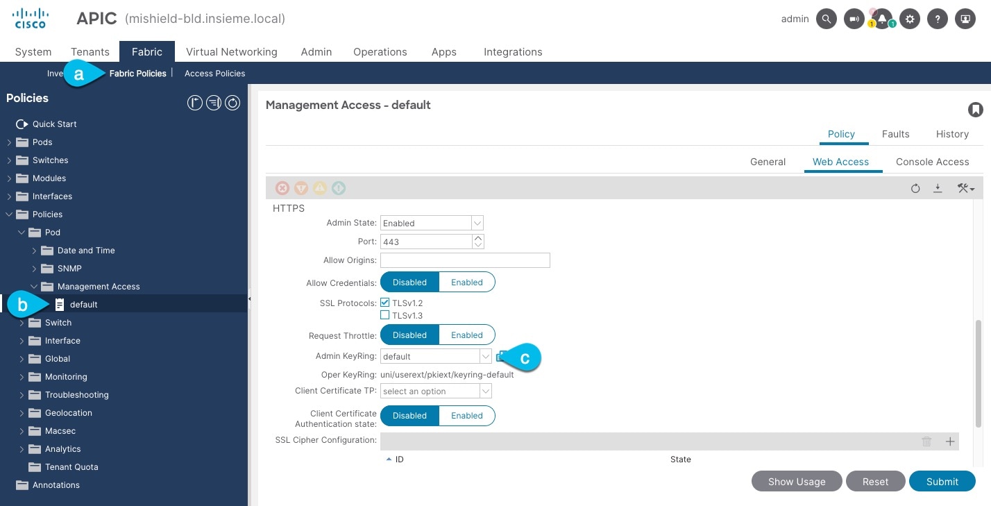
-
In the top navigation bar, choose Fabric > Fabric Policies.
-
In the left navigation menu, choose Policies > Pod> Management Access.
-
In the main pane, note the name in the Admin KeyRing field.
In the above example, the
defaultkey ring is being used. However, if you created a custom key ring with a custom certificate chain, the name of that key ring would be listed in the Admin KeyRing field.Custom security configuration for Cisco APIC is described in detail in Cisco APIC Security Configuration Guide for your release.
-
-
Export the certificate used by the key ring:
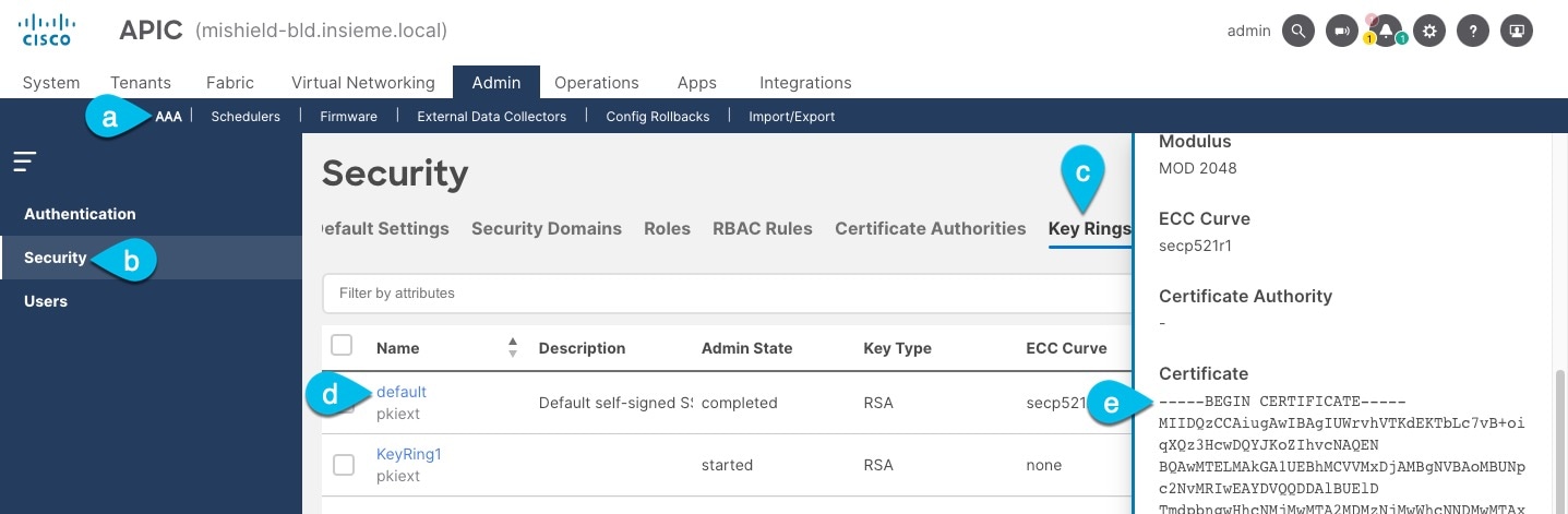
-
In the top navigation bar, choose Admin > AAA.
-
In the left navigation menu, choose Security.
-
In the main pane, choose the Key Rings tab.
-
Click the name of the key ring you found in the previous step and copy the Certificate.
The above example shows the
defaultkey ring from the previous step. However, if you had a custom key ring configured, choose the CA certificate chain used to create the key ring.You must include the
-----BEGIN CERTIFICATE-----and-----END CERTIFICATE-----in the text you copy, for example:-----BEGIN CERTIFICATE----- MIIDQzCCAiugAwIBAgIUWrvhVTKdEKTbLc7vB+oiqXQz3HcwDQYJKoZIhvcNAQEN [...] -----END CERTIFICATE-----
-
Importing certificates into Nexus Dashboard
-
Log in to your Nexus Dashboard where you plan to onboard the fabrics.
-
Import the certificate into Nexus Dashboard.
-
Log in to your Nexus Dashboard where you will onboard the fabrics.
-
From the main navigation menu, choose Admin > Certificate Management.
-
Click the CA Certificates tab.
-
Click Add CA certificate, provide a unique name for the certificate, and paste the certificate chain you copied from your fabric’s controller.
-
-
Proceed with adding the fabric as you typically would, but enable the Verify Peer Certificate option.
Note that if you enable the Verify Peer Certificate option but don’t import the valid certificate, fabric onboarding will fail.
Adding fabrics is described in Creating LAN and ACI Fabrics and Fabric Groups.
Working with VRFs
Use the VRFs tab to create, edit, delete, attach, detach, import, export, and deploy configurations for VRFs. You can create networks only after creating a VRF except when creating Layer 2 only networks.
-
Click Segmentation and security.
-
Click VRFs.
-
Review the information on the VRFs page.
The Segmentation and security > VRFs page shows information on already-configured VRFs.
The default overlay mode for a VRF or network is cli and is available only for Data Center VXLAN EVPN and routed fabrics. To create overlay VRFs, create VRFs for the fabric and deploy them on the fabric switches. Before attaching or deploying the VRFs, set the overlay mode. For more information on how to choose the overlay mode, see the section "Overlay Mode" in Editing Data Center VXLAN Fabric Settings or Editing Routed Fabric Settings.
View VRF information
-
Review the information provided on the VRFs page.
-
Clicking the View in Topology > Config-Sync-Status button provides a visual representation of all the VRFs in the fabric.
The table provides information on individual VRFs in the fabric.
VRFs fields and descriptions Field Description VRF Name
Specifies the name of the VRF.
Default Security Action
Displays the default security action applied to the VRF.
-
Unenforced: There are no default security policies in place and therefore no security action is taken on the traffic that passes.
-
Enforced Permit: Based on a deny list model, where traffic will be permitted on this VRF by default.
-
Enforced Deny: Based on a permit list model, where traffic will be denied on this VRF by default.
Default Security Tag
Displays the default security tag associated with the VRF.
Contract Associations
Shows the number of contract associations that are associated with the VRF. Click the number in the column to navigate directly to the Security associations page (Manage > Fabrics > Fabric Overview > Segmentation and security > Security Associations).
VRF Status
Specifies whether the status of the VRF deployment as Not applicable, Out of Sync, Pending, Deployed, and so on.
VRF ID
Specifies the ID for the VRF or allows you to enter an ID for the VRF.
-
-
Perform any of the following actions on the VRFs page.
This table describes the action items that are available in the Actions drop-down list.
VRFs actions and descriptions Action Item Description Edit
Allows you to edit the chosen VRF.
-
To edit a VRF, choose the check box next to the VRF that you want to edit and choose Edit.
On the Edit VRF page, you can edit the parameters.
-
Click Save to retain the changes or click Close to discard the changes.
Multi-attach
Allows you to provision the VRF on multiple switches.
-
To attach a VRF, choose the check box next to the VRF that you want to attach the switches to and choose Multi-attach.
On the Multi-attach of VRFs page, you can specify the switches where you want to deploy the VRF.
-
Click Next to proceed to the next step in the wizard or click Cancel to discard the changes.
The Summary page displays with the Proceed to Full Switch Deploy (Recommended) button selected.
-
Click Save.
The Deploy Configuration page appears.
-
Click Deploy All.
The Deploy Configuration page appears with an updated status of SUCCESS, Status Description, and Progress indicator.
-
Click Close.
The attached VRF displays as DEPLOYED in the VRF Status column.
Multi-detach
Allows you to remove the VRF configuration from the selected switches.
-
To detach a VRF, choose the check box next to the VRF that you want to detach and choose Multi-detach.
On the Multi-detach of VRFs page, you can specify the switches where you want to remove the VRF configuration.
-
Choose the check box for the switch that you want to detach from the VRF.
-
Click Next.
The Summary page displays with the Proceed to Full Switch Deploy (Recommended) button selected.
-
Click Save.
The Deploy Configuration page appears with the chosen switch.
-
Click Deploy All.
-
Click Close.
Deploy
Allows you to deploy the configuration for the chosen VRF.
-
To deploy a VRF configuration, choose the check box next to the VRF for which you want to deploy the configuration and choose Deploy.
On the Deploy Configuration page, you can deploy the specified VRF configuration.
-
Click Deploy or click Close to discard the changes.
Import
Allows you to import VRF information from a .csv file.
-
To import VRF information from a .csv file, choose Import.
The Import VRFs dialog box appears.
-
Browse to the directory and select the .csv file that contains the VRF information.
-
Click OK.
The VRF information is imported and displayed on the VRFs page.
Export
Allows you to export VRF information to a .csv file. The exported .csv file will then contain information pertaining to each VRF, including the configuration details that you saved during the creation of the VRF.
To export VRF information, choose Export.
The VRF .csv file is exported to your local directory. The file name is appended with the date and time at which the file was exported.
You can use the exported .csv file for reference or use it as a template for creating new VRFs.
Delete
Allows you to delete a selected VRF. You can select multiple VRF entries and delete them at the same time.
-
To delete a VRF, choose the check box next to the VRF that you want to delete and choose Delete.
A warning message appears asking whether you want to delete the VRF(s).
-
Click Confirm to delete or click Cancel to retain the VRF.
A message appears that the selected VRFs are deleted successfully.
-
Create a VRF
-
On the VRFs page, click Create VRF.
The Create VRF page appears.
-
On the Create VRF page, enter the required details in the mandatory fields. The available fields vary based on the fabric type.
The table describes the fields available on the Create VRF page.
Field Description VRF Name
Specifies a VRF name automatically or allows you to enter a name. The VRF name should not contain any white spaces or special characters except underscore (_), hyphen (-), and colon (:).
VRF ID
Specifies the ID for the VRF or enter an ID for the VRF.
VLAN ID
Specifies the corresponding tenant VLAN ID for the network or enter an ID for the VLAN. If you want to propose a new VLAN for the network, click Propose VLAN.
Default Security Action
Related to the security groups feature. For more information on security groups, see Working with security groups.
The following options are available for the Default Security Action field:
-
Unenforced: Default setting. There are no default security policies in place and therefore no security action is taken on the traffic that passes.
-
Enforced Permit: Based on a deny list model, where traffic will be permitted on this VRF by default. You can configure granular contracts to deny specific traffic.
-
Enforced Deny: Based on a permit list model, where traffic will be denied on this VRF by default. You can configure granular contracts to permit specific traffic.
Default Security Tag for VRF
Related to the security groups feature. For more information on security groups, see Working with security groups.
The value in this field will be automatically populated from the Security Tag Pool. This tag is used by default for traffic on this VRF unless the IP address or VLAN of that traffic is specifically classified as a selector under a security group.
VRF Template
A default universal template is auto-populated. This is applicable for leaf switches only.
VRF Extension Template
A default universal extension template is auto-populated. This allows you to extend this network to another fabric. The methods are VRF Lite, Multi Site, and so on. The template is applicable for border leaf switches and BGWs.
-
-
Enter the necessary field values or edit pre-filled fields, as required.
The tabs and their fields on the page are explained in the following sections.
-
Click Create to create the VRF or click Close to discard the VRF.
A message appears indicating that the VRF is created.
The new VRF appears on the VRFs horizontal tab. The status is shown as Not applicable because the VRF is created but is not yet deployed. Double-click on the configured VRF to bring up the VRF Attachments information.
If you did not associate a VLAN with a VRF when you created the VRF using these instructions, you will see
Not applicabledisplayed in the VRF Attachments for the VRF, even if a VLAN was associated with the VRF through another process (for example, if you disabled the Enable L3VNI w/o VLAN setting).
Now that the VRF is created, you can create and deploy networks on the devices in the fabric.
General Parameters
The General Parameters tab is displayed by default. The fields in this tab are described in this table.
| Field | Description |
|---|---|
|
VRF VLAN Name |
Enter the VLAN name for the VRF. |
|
VRF Interface Description |
Enter a description for the VRF interface. |
|
VRF Description |
Enter a description for the VRF. |
Advanced
This table describes the fields on the Advanced tab.
| Field | Description |
|---|---|
|
VRF Interface MTU |
Specifies the VRF interface MTU. |
|
Loopback Routing Tag |
If a VLAN is associated with multiple subnets, then this tag is associated with the IP prefix of each subnet. Note that this routing tag is associated with overlay network creation also. |
|
Redistribute Direct Route Map |
Specifies the redistribute direct route map name. |
|
Max BGP Paths |
Specifies the maximum number of BGP paths. The valid value is between 1 and 64. |
|
Max iBGP Paths |
Specifies the maximum number of iBGP paths. The valid value is between 1 and 64. |
|
Enable IPv6 link-local Option |
Select the check box to enable the IPv6 link-local option under the VRF SVI. If this check box is unchecked, IPv6 forwarding is enabled. |
|
Enable L3VNI w/o VLAN |
Check the box to enable the L3VNI w/o VLAN configuration. The default value of this field comes from the fabric-level field Enable L3VNI w/o VLAN. The default setting for this field varies depending on the following factors:
|
|
Advertise Host Routes |
Check this check box to control advertisement of /32 and /128 routes to edge routers. |
|
Advertise Default Route |
Check this check box to control advertisement of default route internally. To allow inter-subnet communication between end hosts in different VXLAN fabrics, where the subnets are present in both fabrics, you must disable the Advertise Default Route feature (clear the Advertise Default Route check box) for the associated VRF. This will result in /32 routes for hosts in both fabrics. For example, Host1 (VNI 30000, VRF 50001) in Fabric1 can send traffic to Host2 (VNI 30001, VRF 50001) in Fabric2 only if the host route is present in both fabrics. When a subnet is present in one fabric only then the default route is sufficient for inter-subnet communication. |
|
Config Static 0/0 Route |
Check this check box to control configuration of static default route. |
|
BGP Neighbor Password |
Specifies the VRF-Lite BGP neighbor password. |
|
BGP Password Key Encryption Type |
From the drop-down list, select the encryption type. |
|
Enable Netflow |
Allows you to enable netflow monitoring on the VRF-Lite sub-interface. Note that this is supported only if netflow is enabled on the fabric. |
|
Netflow Monitor |
Specifies the monitor for the VRF-Lite netflow configuration. To enable netflow on a VRF-Lite sub-interface, you must enable netflow at the VRF level and VRF extension level. Check the Enable_IFC_Netflow check box in the VRF attachment while you edit an extension to enable netflow monitoring. For more information, see the "Configuring Netflow support" section in Creating LAN and ACI Fabrics and Fabric Groups. |
TRM
Use the TRM tab for configuring Tenant Routed Multicast (TRM) for IPv4 or IPv6.
For more information on TRM, see the section "Overview of Tenant Routed Multicast" in Editing Data Center VXLAN EVPN Fabric Settings.
This table describes the fields on the TRM tab.
| Field | Description |
|---|---|
|
IPv4 TRM Enable |
Check the check box to enable IPv4 TRM. If you enable IPv4 TRM, and provide the RP address, you must enter the underlay multicast address in the Underlay Mcast Address field. |
|
NO RP |
Check the check box to disable RP fields. You must enable IPv4 TRM to edit this check box. If you enable No RP, then the Is RP External, RP Address, RP Loopback ID, and Overlay Mcast Groups fields are disabled. |
|
Is RP External |
Check this check box if the RP is external to the fabric. If this check box is not checked, RP is distributed in every VTEP. |
|
RP Address |
Specifies the IP address of the RP. |
|
RP Loopback ID |
Specifies the loopback ID of the RP, if Is RP External is not enabled. |
|
Underlay Multicast Address |
Specifies the multicast address associated with the VRF. The multicast address is used for transporting multicast traffic in the fabric underlay.
The multicast address in the Default MDT Address for TRM VRFs field on the fabric settings page is auto-populated in this field. You can override this field if a different multicast group address should be used for this VRF. |
|
Overlay Mcast Groups |
Specifies the multicast group subnet for the specified RP. The value is the group range in the |
|
TRMv6 Enable |
Check this check box to enable IPv6 TRM. |
|
TRMv6 No RP |
Check this check box to disable RP fields in TRMv6 as only PIM-SSM is used. |
|
Is TRMv6 RP External |
Check this check box if the RP is external to the fabric in TRMv6. |
|
TRMv6 RP Address |
Enter the IPv6 address of the TRMv6 RP multicast traffic. |
|
Overlay IPv6 Mcast Groups |
Specifies the IPv6 multicast group subnet for the specified TRMv6 RP. The value is the group range in the |
|
Enable MVPN inter-as |
Check this check box to use the inter-AS keyword for the Multicast VPN (MVPN) address family routes to cross the BGP autonomous system (AS) boundary. This option is applicable if you enabled the TRM option. |
|
Enable IPv4/IPv6 TRM BGW MSite |
Check this check box to enable IPv4 or IPv6 TRM on BGW multisite. |
Route Target
This table describes the fields on the Route Target tab.
| Field | Description |
|---|---|
|
Disable RT Auto-Generate |
Check this check box to disable RT auto-generate for IPv4, IPv6 VPN/EVPN/MVPN. |
|
Import |
Specifies one VPN route target or a comma-separated list of VPN route targets to import. |
|
Export |
Specifies one VPN route target or a comma-separated list of VPN route targets to export. |
|
Import EVPN |
Specifies one EVPN route target or a comma-separated list of EVPN route targets to import. |
|
Export EVPN |
Specifies one EVPN route target or a comma-separated list of EVPN route targets to export. |
|
Import MVPN |
Specifies one MVPN route target or a comma-separated list of MVPN route targets to import. |
|
Export MVPN |
Specifies on MVPN route target or a comma-separated list of MVPN route targets to export.
By default, Import MVPN and Export MVPN fields are disabled. Check the IPv4 TRM Enable or the TRMv6 Enable check box to enable these fields. |
VRF attachments
Use this page to attach or detach attachments to or from a VRF, respectively. You can also import or export the attachments for a VRF.
This table describes the fields on VRF Attachments.
|
Field |
Description |
|
VRF Name |
Specifies the name of the VRF. |
|
VRF ID |
Specifies the ID of the VRF. |
|
VLAN ID |
Specifies the VLAN ID. |
|
Switch |
Specifies the name of the switch. |
|
Status |
Specifies the status of VRF attachments, for example, pending, Not applicable, deployed, out-of-sync, and so on. |
|
Attachment |
Specifies whether the VRF attachment is attached or detached. |
|
Switch Role |
Specifies the switch role. For example, for the fabric created using the Campus VXLAN EVPN fabric template, the switch role is specified as either leaf, spine, or border. |
|
Fabric Name |
Specifies the name of the fabric to which the VRF is attached or detached. |
|
Loopback ID |
Specifies the loopback ID. |
|
Loopback IPV4 Address |
Specifies the loopback IPv4 address. |
|
Loopback IPV6 Address |
Specifies the loopback IPv6 address.
The IPv6 address is not supported for underlay. |
Click the table header to sort the entries in alphabetical order of that parameter.
The following table describes the action items, in the Actions drop-down list, that appear on the VRF Attachments horizontal tab of the VRFs tab on the Fabric Overview page.
| Action Item | Description |
|---|---|
|
History |
Allows you to view the deployment and policy change history of the selected VRF. You can view the deployment history details of a VRF attachment such as hostname, VRF name, commands, status, status description, user, and completed time on the Deployment History tab. You can view the policy change history details such as policy ID, template, description, PTI operation, generated configuration, entity name and type, created date, serial number, user, and source of the policy on the Policy Change History tab. To view the history of a VRF attachment, check the check box next to the VRF name and select History. The History page appears. Click the Deployment History or Policy Change History tabs as required. You can also click the Detailed History link in the Commands column of the Deployment History tab to view the command execution details (comprising configuration, status, and CLI response) for the host. |
|
Edit |
Allows you to view or edit the VRF attachment parameters such as interfaces that you want to attach to the selected VRF. To edit the VRF attachment information, check the check box next to the VRF name that you want to edit. Select Edit. In the Extension page, edit the required values, attach or detach the VRF attachment. Click the Edit link to edit the CLI freeform config for the switch, and click Save to apply the changes or click Cancel to discard the changes. The edited VRF attachment is shown in the table on the VRF Attachments horizontal tab of the VRFs tab in the Fabric Overview page. |
|
Preview |
Allows you to preview the configuration of the VRF attachments for the selected VRF.
This action is not allowed for attachments that are in deployed or Not applicable status. To preview the VRF, check the check box next to the VRF name and choose Preview from Actions drop-down list. The Preview Configuration page for the fabric appears. You can preview the VRF attachment details such as the VRF name, fabric name, switch name, serial number, IP address, and role, VRF status, pending configuration, and progress of the configuration. Click the lines link in the Pending Config column to view the lines for which the configuration is pending. Click Close. |
|
Deploy |
Allows you to deploy the pending configuration of the VRF attachments, for example, interfaces, for the selected VRF.
This action is not allowed for attachments that are in deployed or Not applicable status. To deploy a VRF, check the check box next to the VRF name and choose Deploy from Actions drop-down list. The Deploy Configuration page for the fabric appears. You can view the details such as the VRF name, fabric name, switch name, serial number, IP address, and role, VRF status, pending configuration, and progress of the configuration. Click the lines link in the Pending Config column to view the lines for which the configuration is pending. Click the Deploy button. The status and progress of the deployment is displayed in the VRF Status and Progress columns. After the deployment is completed successfully, close the page. |
|
Import |
Allows you to import information about VRF attachments for the selected fabric. To import the VRF attachments information, choose Import. Browse the directory and select the .csv file that contains the VRF attachments information. Click Open and then click OK. The VRF information is imported and displayed in the VRF Attachments horizontal tab on the VRFs tab on the Fabric Overview page. |
|
Export |
Allows you to export the information about VRF attachments to a .csv file. The exported file contains information pertaining to each VRF, including the fabric it belongs to, whether the LAN is attached, the associated VLAN, serial number, interfaces, and freeform configuration details that you saved for VRF attachments. To export VRF attachments information, choose the Export action. Select a location on your local system directory to store the VRF information and click Save. The VRF information file is exported to your local directory. The file name is appended with the date and time at which the file was exported. |
|
Quick attach |
Allows you to immediately attach an attachment to the selected VRF. You can select multiple entries and attach them to a VRF at the same instance. To quickly attach any attachment to a VRF, choose Quick attach from Actions drop-down list. A message appears to inform that the attach action was successful. |
|
Quick detach |
Allows you to detach the selected VRF immediately from an attachment, for example, a fabric. You can select multiple entries and detach them from an attachment at the same instance. To detach any attachment to a VRF quickly, choose Quick detach from Actions drop-down list. A message appears to inform that the detach action was successful. |
Working with networks
-
On the Segmentation and security tab, click the Networks subtab.
-
Review the information on the Networks page.
The Networks page shows information on already-configured networks.
Before creating networks, ensure that you have created a VRF for the fabric. However, if you have chosen Layer 2, you do not require a VRF. For more information about VRFs, see Working with VRFs.
To create overlay networks, create networks for the fabric and deploy them on the fabric switches. Before deploying the networks, set the overlay mode. For more information on how to choose the overlay mode, see the section "Overlay Mode" in Editing Data Center VXLAN Fabric Settings.
For more information on creating interface groups and attaching networks, see the section "Interface groups" in Working with Connectivity in Your Nexus Dashboard LAN Fabrics.
You can view the network details on the Networks tab and network attachment details on the Network attachments tab.
View network information
-
Review the information provided on the Networks page.
The table provides information on individual networks in the fabric.
Networks Table Fields and Description Field Description Network Name
Specifies the name of the network.
Network ID
Specifies the Layer 2 virtual network interface (VNI) of the network.
VRF Name
Specifies the name of the VRF that’s associated with the network.
IPv4 Gateway Address/Prefix
Specifies the IPv4 address with a prefix.
IPv6 Gateway Address/Prefix
Specifies the IPv6 address with a prefix.
Network Status
Specifies the status of the network deployment as Not applicable, Out of Sync, Pending, Deployed, and so on.
VLAN ID
Specifies the VLAN ID for the network.
VLAN Name
Specifies the name of the VLAN.
Interface Group
Specifies the interface group. An interface group consists of multiple interfaces with the same attributes. You can create an interface group that allows grouping of host-facing interfaces at the fabric level. Specifically, you can create an interface group for physical Ethernet interfaces, Layer 2 port-channels, and vPCs. You can attach or detach multiple overlay networks to the interfaces in an interface group.
-
Click the gear icon to the right of the table to change the columns in the table.
-
Click the toggle switch to enable or disable the column options.
-
Click Filter by attributes to filter information based on the chosen parameter.
-
Click the column header to sort the entries in alphabetical order for the chosen parameter.
-
Perform any of these actions on the Networks page.
This table describes the action items that are available in the Actions drop-down list.
Networks Actions and Description Action Item Description Create
Allows you to create a network.
Edit
Allows you to view or edit the selected network parameters.
-
To edit the network information, check the check box next to the network name that you want to edit and choose Edit.
-
On the Edit Network page, edit the required values and click Save to apply the changes or click Close to discard the changes.
Multi-attach
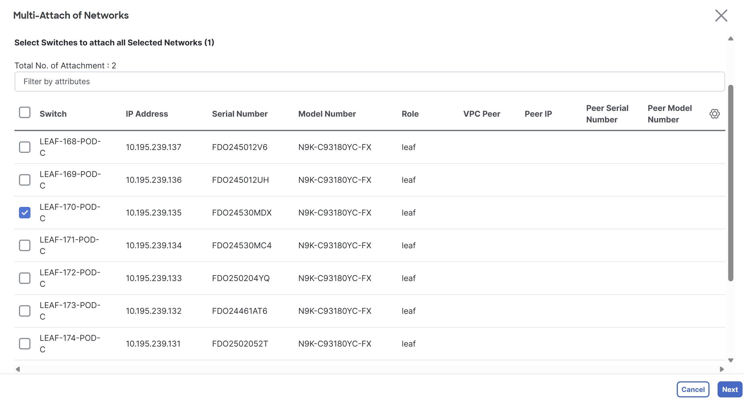
Allows you to attach networks to multiple switches and interfaces at the same time.
-
To attach the selected switches and interfaces to the network, check the check box next to the network name that you want to attach and choose Multi-attach.
-
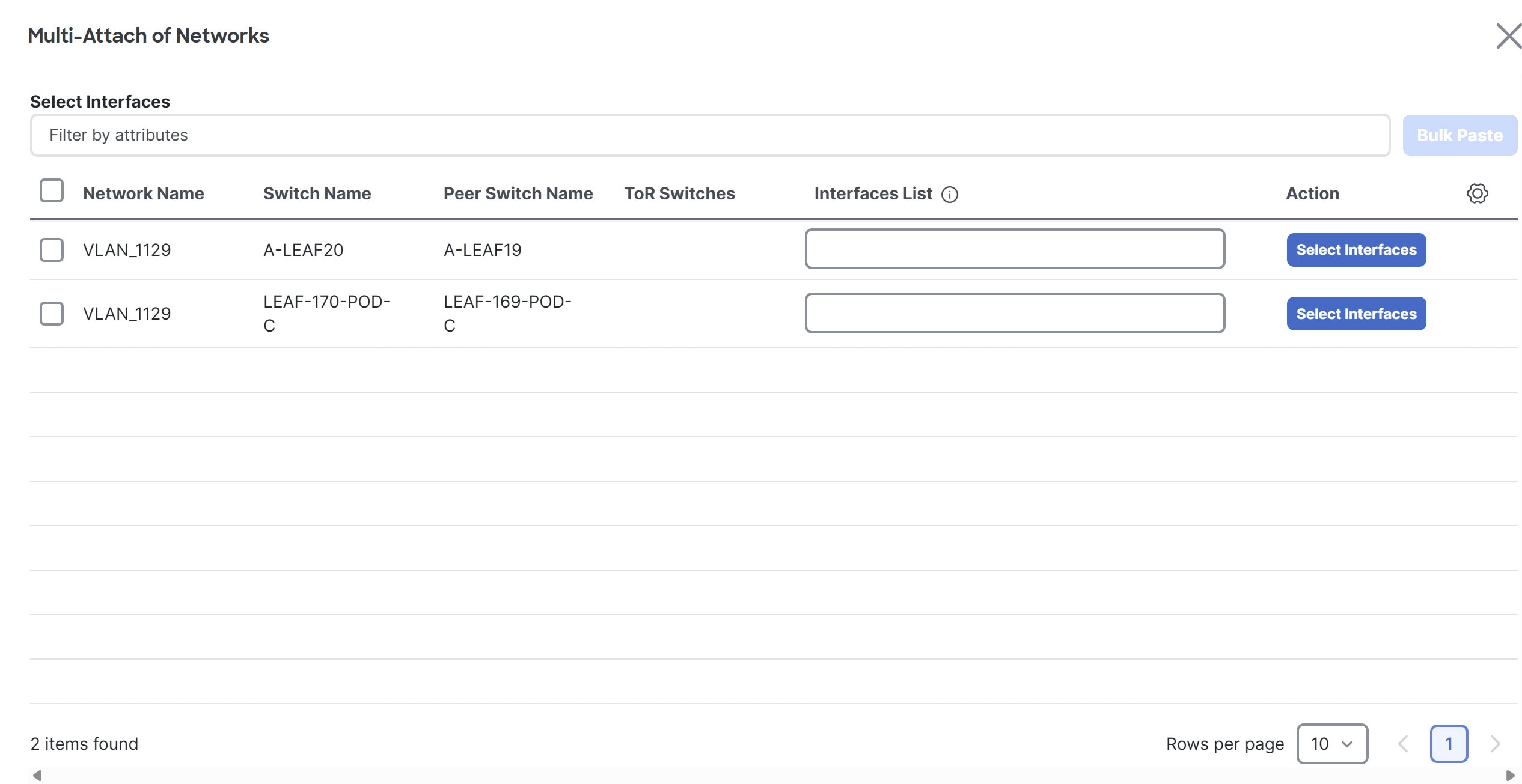
On the Multi-attach of Networks page, check the check boxes for the switches that you want to attach to the network and click Next.
-
In the Select Interfaces area, check the check boxes for the interfaces that you want to attach to the network and click Next.
The Summary page displays with the Proceed to Full Switch Deploy (Recommended) option selected.
-
Click Save.
The Deploy Configuration page appears with the selected switch.
-
Click Deploy All.
The Deploy Configuration page appears with an updated status of SUCCESS, Status Description, and Progress indicator.
-
Click Close.
The attached network displays as DEPLOYED in the Network Status column in the Networks tab.
Multi-detach
Allows you to detach multiple switches from the network at the same time.
-
To detach the selected switches from the network, select the check box next to the network name that you want to detach and choose Multi-detach.
-
On the Multi-detach of Networks page, check the check boxes for the switches that you want to detach from the network and click Next.
The Summary page displays with the Proceed to Full Switch Deploy (Recommended) option selected.
-
Click Save.
The Deploy Configuration page appears with the selected switch.
-
Click Deploy All.
The Deploy Configuration page appears with an updated status of SUCCESS, Status Description, and Progress indicator.
-
Click Close.
The detached network displays as Not applicable in the Network Status column in the Networks tab.
Deploy
Allows you to deploy the pending configuration for associating the switches or interfaces to the network.
-
To deploy a network, check the check box next to the network name that you want to deploy and choose Deploy.
The Deploy Configuration page for the fabric appears. You can view the details such as the network name, fabric name, switch name, serial number, IP address, and role, network status, pending configuration, and progress of the configuration.
-
Click the Lines link in the Pending Config column to view the lines of the pending configuration.
The Pending Config dialog box appears.
-
Click Cancel after you have viewed the pending configuration.
-
On the Deploy Configuration page, click the Deploy button.
The status and progress of the deployment displays in the Network Status and the Progress columns.
-
After the deployment completes successfully, close the page.
Import
Allows you to import network information for the fabric.
-
To import network information, choose Import.
The Import Networks dialog box appears.
-
Browse to the directory with the .csv file that contains the host IP address and corresponding unique network information.
-
Click OK.
The host aliases are imported and displayed in the Networks tab.
Export
Allows you to export network information to a .csv file. The exported file contains information pertaining to each network, including the fabric it belongs to, the associated VRF, the network templates used to create the network, and all other configuration details that you saved during network creation. You can use the exported .csv file for reference or use it as a template for creating new networks.
-
To export network information, choose Export.
The network information file is exported to your local directory. The file name is appended with the date and time at which the file was exported.
The Networks tab displays network names based on the number of rows per page. You can view network names based on the options in the Rows per page drop-down list. When you use the Export option, Nexus Dashboard exports the network names as displayed per page. If you have a large number of network names and you want to export all of your network names, you need to navigate to each page and export each page individually.
-
Before importing the file, update new records in the .csv file.
-
Ensure that the networkTemplateConfig field contains the JSON Object.
Delete
Allows you to delete the network. You can select multiple network entries and delete them at the same time.
-
To delete a network for the fabric, select the check box next to the network name that you want to delete and choose Delete.
A Warning dialog box appears.
-
Click Confirm to delete the network.
Add to interface group
Allows you to add the network to an interface group. You can choose multiple network entries and add them to an interface group at the same time.
-
To associate the selected networks to the interface group that you want, check the check box for the network name you want and click Add to interface group.
-
On the Add to interface group page, click the network that you want to add and verify whether the selected network is present on the Selected Networks page and then click Cancel.
-
Either choose an Interface Group from the drop-down list or click Create interface group.
-
On the Create interface group page, provide the interface group name, choose the interface type, and then click Create to save the changes or click Close to close the page and discard the changes.
-
On the Add to interface group page, click Save to save the changes or click Close to close the page and discard the changes.
The interface group displays in the Interface Group column on the Networks tab.
-
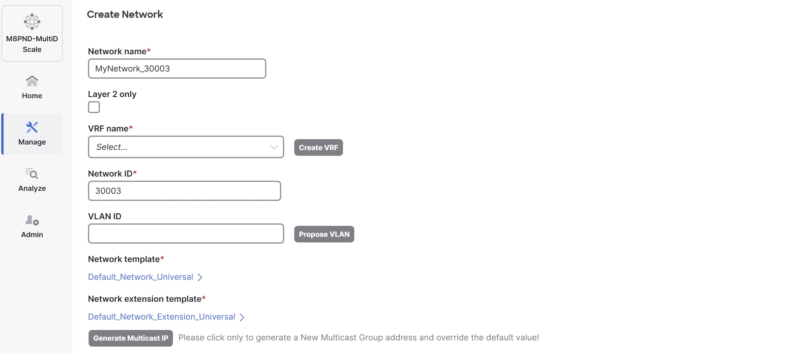
Create a network
Before creating networks, ensure that you have created a VRF for the fabric. However, if you have chosen Layer 2 on the Create Network page, then you do not require a VRF. For more information, see Working with VRFs.
-
On the Networks page, click Actions > Create.
The Create network page appears.
-
On the Create network page, enter the required details in the mandatory fields. The available fields vary based on the fabric type.
Field Description Network name
Specifies the Layer 2 VNI and the name of the network. The network name should not contain any white spaces or special characters, except underscore (_) and hyphen (-). The corresponding Layer 3 VNI (or VRF VNI) is generated along with VRF creation.
Layer 2 only
Specifies whether the network is Layer 2 only.
VRF Name
Allows you to select the Virtual Routing and Forwarding (VRF) from the drop-down list. If you want to create a new VRF, click Create VRF. The VRF name should not contain any white spaces or special characters except underscore (_), hyphen (-), and colon (:).
Network ID
Specifies the Layer 2 VNI and the name of the network. The network name should not contain any white spaces or special characters, except underscore (_) and hyphen (-). The corresponding Layer 3 VNI (or VRF VNI) is generated along with VRF creation.
VLAN ID
Specifies the corresponding tenant VLAN ID for the network. If you want to propose a new VLAN for the network, click Propose VLAN.
Network template
A default universal template is auto-populated. This is only applicable for leaf switches.
Network extension template
A default universal extension template is auto-populated. This allows you to extend this network to another fabric. The methods are VRF Lite, Multi Site, and so on. The template is applicable for border leaf switches and BGWs.
Generate Multicast IP
Click to generate a new multicast group address and override the default value.
-
Enter the necessary field values or edit pre-filled fields, as required.
The tabs and their fields in the screen are explained in these sections.
-
Click Create.
A message appears indicating that the network is created.
The new network appears on the Networks page that comes up.
The Status is Not applicable since the network is created but not yet deployed on the switches. Now that the network is created, you can create more networks if necessary and deploy the networks on the devices in the fabric.
General Parameters
The fields on the General Parameters tab are:
| Field | Description |
|---|---|
|
IPv4 Gateway/NetMask |
Specifies the IPv4 address with subnet. Specify the anycast gateway IP address for transporting the L3 traffic from a server belonging to MyNetwork_30000 and a server from another virtual network. The anycast gateway IP address is the same for MyNetwork_30000 on all switches of the fabric that have the presence of the network.
If the network is a non-Layer 2 network, then it is mandatory to provide the gateway IP address.
The primary gateway IP address should match IP address provided in the IPv4 secondary gateway list field. |
|
IPv6 Gateway/Prefix List |
Specifies the IPv6 address with subnet. |
|
VLAN Name |
Enter the VLAN name. |
|
Interface Description |
Specifies the description for the interface. This interface is a switch virtual interface (SVI). |
|
MTU for L3 interface |
Enter the MTU for Layer 3 interfaces in the range of 68 - 9216. |
|
IPv4 Secondary Gateway List (Max 16) |
Configure up to 16 secondary gateway IP addresses when creating or editing a network. Click Actions > Add to add the secondary gateway IP addresses. For more information, see Configure a secondary gateway IP address. |
|
Secondary IPv4 Gateway/Netmask |
Check this check box to delete all the IP addresses listed in the table. Click Actions > Delete to delete all the secondary gateway IP addresses. |
|
Downstream VNI |
Configure downstream VNI. For more information, see the section "Configuring downstream VNI" in Creating LAN and ACI Fabrics and Fabric Groups. |
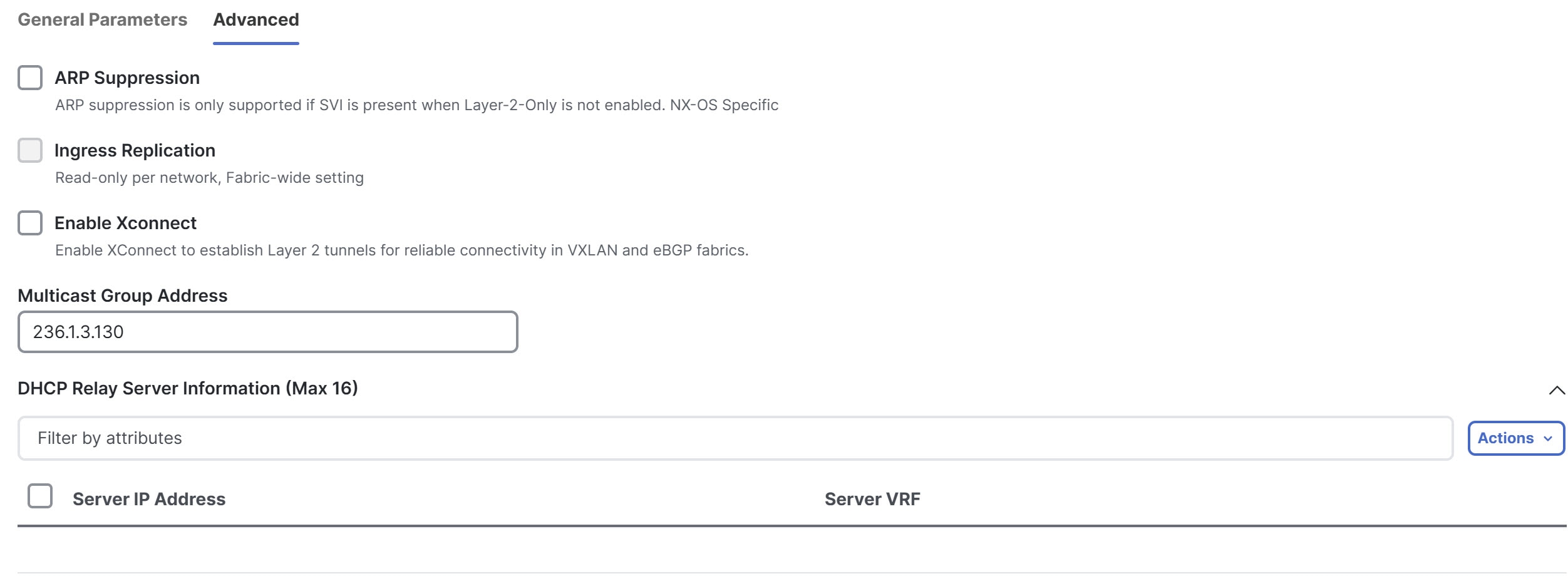
Advanced
The fields on the Advanced tab are:
| Field | Description |
|---|---|
|
ARP Suppression |
Choose the check box to enable the ARP Suppression function. |
|
Ingress Replication |
The check box is selected if the replication mode is ingress replication.
Ingress replication is a read-only option on the Advanced tab. Changing the fabric setting updates the field. |
|
Enable Xconnect |
Enables Xconnect to establish Layer 2 tunnels for reliable connectivity in VXLAN and eBGP fabrics.
VXLAN Xconnect supports only Layer 2 networks. You cannot enable Xconnect on a Layer 3 network. You can attach Layer 2 Xconnect networks only to ports configured with a dot1q tunnel policy. Xconnect networks cannot be attached to access or trunk ports. |
|
Multicast Group Address |
The multicast IP address for the network is autopopulated. Multicast group address is a per fabric instance variable. The number of underlay multicast groups supported is 128. If all networks are deployed on all switches, you need not use a different multicast group per L2 VNI or a network. Therefore, multicast group for all networks in a fabric remains the same. Perform these steps to include the DHCP relay server information:
|
|
DHCPv4 Server 3 |
Enter the DHCP relay IP address of the next DHCP server. |
|
DHCPv4 Server3 VRF |
Enter the DHCP server VRF ID. |
|
Loopback ID for DHCP Relay interface (Min:0, Max:1023) |
Specifies the loopback ID for DHCP relay interface. |
|
Routing Tag |
The routing tag is autopopulated. This tag is associated with each gateway IP address prefix. |
|
IPv4 TRM enable |
Check the check box to enable TRM with IPv4. For more information, see the "Overview of Tenant Routed Multicast" section in Editing Data Center VXLAN EVPN Fabric Settings. |
|
IPv6 TRM enable |
Check the check box to enable TRM with IPv6. For more information, see the "Overview of Tenant Routed Multicast" section in Editing Data Center VXLAN EVPN Fabric Settings. |
|
L2 VNI Route-Target Both Enable |
Check the check box to enable automatic importing and exporting of route targets for all L2 virtual networks. |
|
Enable Netflow |
Enables netflow monitoring on the network. This is supported only if netflow is already enabled on fabric. |
|
Interface Vlan Netflow Monitor |
Specifies the netflow monitor specified for Layer 3 record for the VLAN interface. This is applicable only if Is Layer 2 Record is not enabled in the Netflow Record for the fabric. |
|
Vlan Netflow Monitor |
Specifies the monitor name defined in the fabric setting for Layer 3 Netflow Record. |
|
Enable L3 Gateway on Border |
Check the check box to enable a Layer 3 gateway on the border switches. |
Enable Xconnect for Layer 2-only network
You can create a Layer 2-only network when the network gateway resides outside the fabric.
VXLAN Xconnect supports only Layer 2 networks. You can attach Layer 2 Xconnect networks only to dot1q ports, not to access or trunk ports.
Follow these steps to enable Xconnect for Layer 2-only network.
-
Navigate to Fabrics page.
Go to Manage > Fabrics.
-
Click the VXLAN fabric. The Fabric Overview page displays.
-
Click the Segmentation and security tab. The Networks tab displays.
-
From the Actions drop-down list, choose Create.
The Create Network page displays.
-
In the Network name field, provide a name for the Layer 2 network.
-
Check the Layer 2 only check box to specify that this network is Layer 2-only network.
-
In the Network ID field, provide the network ID.
-
In the VLAN ID field, provide the VLAN ID for the network, or click Propose VLAN to have Nexus Dashboard suggest an available VLAN ID based on fabric settings.
-
Leave the Network template field as the Default_Network_Universal, which is appropriate for Layer 2 networks.
-
Leave the Network extension template as the Default_Network_Extension_Universal, which is appropriate for Layer 2 networks.
Under the General tab, the gateway IP address fields remain empty because the gateway for a Layer 2 network resides outside the fabric.
-
Click the Advanced tab.
-
Check the Enable Xconnect check box.
This enables Xconnect to establish Layer 2 tunnels for reliable connectivity in VXLAN and eBGP fabrics.
-
Configure any other necessary parameters such as DHCP relay server information or advanced settings, if applicable.
-
Click Create to save the new Layer 2 network.
The Networks tab under Segmentation and security displays the newly created network.
-
From the Actions drop-down list, Choose Deploy to apply the network configuration.
For more information on creating interfaces, see the section "Add interfaces" in Working with Connectivity in Your Nexus Dashboard LAN Fabrics.
Deploy Layer 2-only network
In Layer 2 networks with Xconnect enabled, you must configure dot1q policy on any interface attached to the network.
Follow these steps to deploy the network to specific interfaces.
-
In the Networks tab under Segmentation and security choose the newly created Layer 2 network, then click Actions > Multi-attach. The Multi-attach of Networks page displays.
-
Choose the switch and click Next.
The Select Interfaces page displays.
-
Click the Select Interfaces button.
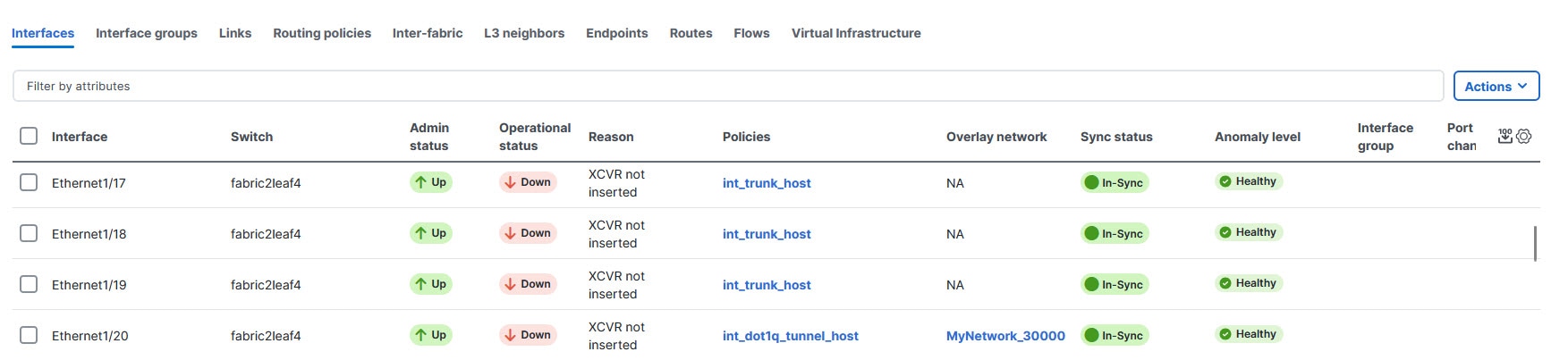
The Select Interfaces of switch name-fabric_name page displays. For L2-only network with Xconnect enabled, this page displays only the interfaces with
dot1q_tunnelport type.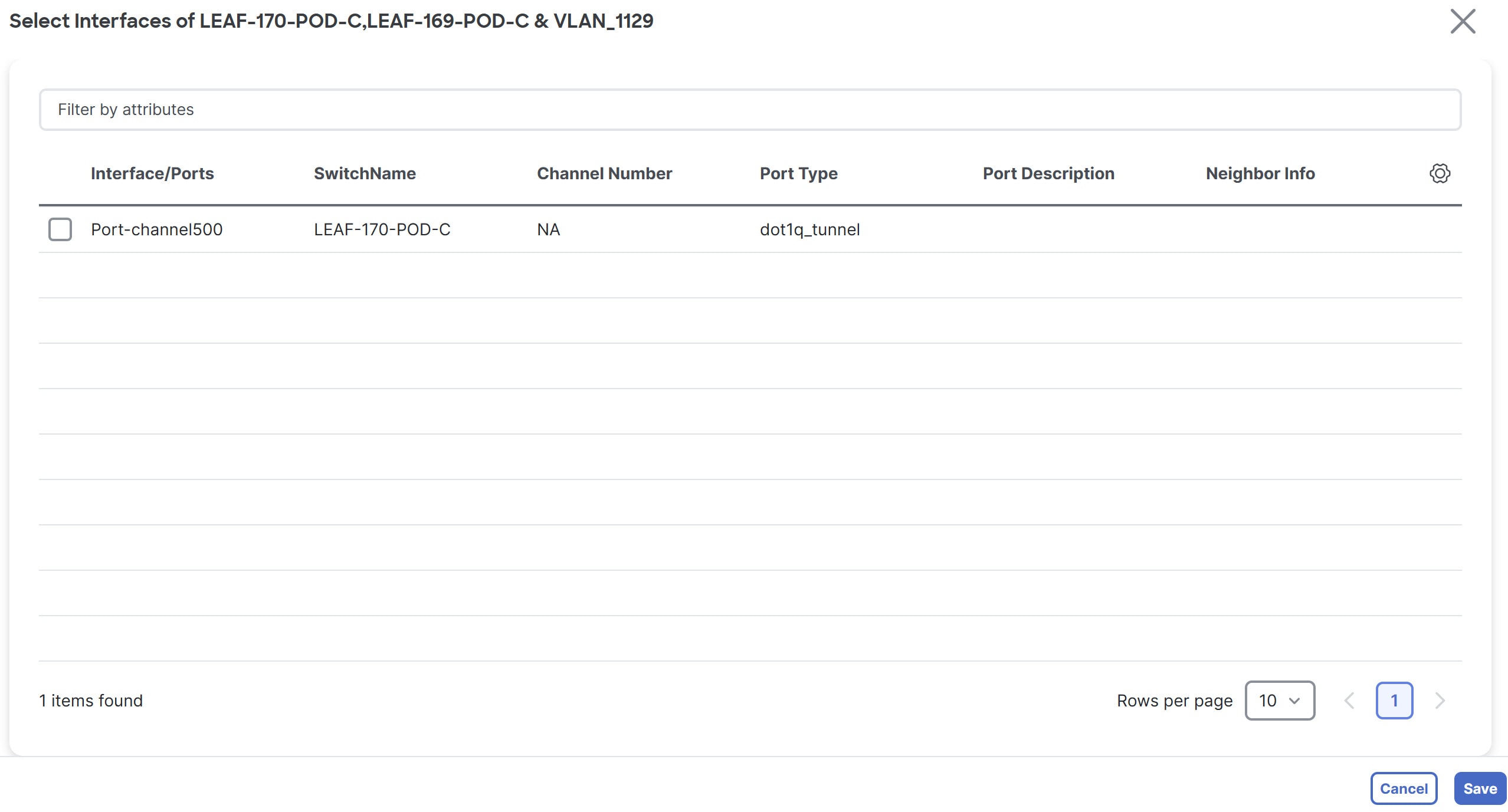
You can view the interfaces with
dot1q_tunnelport type in the Interface table. From the Fabric Overview page, navigate to Connectivity > Interface to view the Interface table.
-
Choose the interface and click Save.
The Select Interfaces page displays, with the Interface List field listed.
-
Click Next.
The Multi-attach Networks page with a summary displays.
-
Choose Proceed to individual network deploy and click Save.
The Deploy Configuration page displays.
-
Click Deploy.
Edit a network
Follow these steps to edit a network.
-
Navigate to Manage Fabrics > Fabric Overview > Segmentation and security > Networks.
-
Click on the network that you want to edit.
-
Click Actions > Edit.
The Edit Network page displays.
For the fields and descriptions on the Edit Network page, see Create a network.
Configure a secondary gateway IP address
With this feature, Nexus Dashboard added support for configuring up to 16 secondary IP addresses in a list rather than in individual fields when creating or editing a network. Prior to 4.1.1, Nexus Dashboard supported adding four secondary gateway IP addresses in individual fields when creating or editing a network.
This feature is available for these fabric types.
-
Campus VXLAN EVPN
-
Data Center VXLAN EVPN
Follow these steps to add secondary gateway IP addresses.
-
Navigate to Segmentation and security > Networks.
-
Click on a network for which you want to add a secondary gateway IP address.
-
Click Actions > Edit.
The Edit Network page displays.
-
Ensure that you are on the General Parameters tab.
-
On the Edit Network page in the IPv4 Secondary Gateway List (Max 16) section, click Actions > Add.
The Add Item dialog box appears.
-
Enter the Secondary IPv4 Gateway/NetMask field with a secondary gateway IP address and click Save.
You can add a maximum of 16 secondary gateway IP addresses.
-
Repeat these steps until you have added the necessary secondary gateway IP addresses.
-
View the added secondary gateway IP addresses by navigating to Manage > Fabrics > Configuration policies > Resources under the Allocated Resource column.
Guidelines and limitations for adding secondary gateway IP addresses
-
You must configure a primary gateway IP address before adding a secondary gateway IP address. You receive an error if you do not configure a primary gateway IP address.
-
You can configure a maximum of 16 secondary gateway IP addresses. You receive an error if you exceed 16 secondary gateway IP addresses. If you do want to configure 17 or 18 secondary gateway IP addresses, Nexus Dashboard adds the additional secondary gateway IP addresses in the Switch Freeform Config field in a freeform configuration template. Nexus Dashboard does not manage freeform configuration templates. For more information, see Configuration Compliance.
-
If you have a duplicate secondary IP address, Nexus Dashboard generates an error message.
-
Nexus Dashboard pushes the secondary gateway IP addresses in the pending configuration.
-
For existing customers, Nexus Dashboard provides REST APIs for importing legacy device information.
Network attachments
These options are applicable only for switch fabrics, VXLAN EVPN fabrics, and VXLAN fabric groups.
Use the Network attachments page to attach fabrics and interfaces to a network. You can also detach fabrics and interfaces from a network.
-
Choose Manage > Fabrics and click on a fabric.
The Fabric > Overview page displays.
-
Navigate to Segmentation and security > Networks.
-
Click on a network to open the Network > Overview page.
-
Click Network attachments.
This table describes the available fields for configuring a network attachment.
Network Attachments table fields and descriptions Field
Description
Network Name
Specifies the name of the network.
Network ID
Specifies the Layer 2 VNI of the network.
VLAN ID
Specifies the VLAN ID.
Switch
Specifies the name of the switch.
Ports
Specifies the ports for the interfaces.
Status
Specifies the status of the network attachments, for example, pending, Not applicable, and so on.
Attachment
Specifies whether the network attachment is attached or detached.
Switch Role
Specifies the switch role. For example, for the fabric created using the Campus VXLAN EVPN fabric template, the switch role is specified as either leaf, spine, or border.
Fabric Name
Specifies the name of the fabric to which the network is attached or detached.
This table describes the action items, in the Actions drop-down list, that appear on the Network Attachments > Network attachments tab.
Network Attachments actions and descriptions Action Item
Description
History
Allows you to view the deployment and policy change history of the selected network.
You can view the deployment history details of a network attachment such as hostname, network name, VRF name, commands, status, status description, user and completed time on the Deployment History tab.
You can view the policy change history details such as policy ID, template, description, PTI operation, generated configuration, entity name and type, created date, serial number, user, and source of the policy on the Policy Change History tab.
To view the history of a network attachment, select the check box next to the network name and choose the History action. The History page appears. Click the Deployment History or Policy Change History tabs as required. Click the Detailed History link in the Commands column of the Deployment History tab to view the command execution details (comprising configuration, status, and CLI response) for the host.
Edit
Allows you to view or edit the network attachment parameters such as interfaces that you want to attach to the selected network.
To edit the network attachment information, check the check box next to the network name that you want to edit and choose the Edit action. On the Edit Network Attachment page, edit the required values, attach or detach the network attachment, click the Edit link to edit the CLI freeform config for the switch, and click Save to apply the changes or click Cancel to discard the changes. The edited network attachment is shown in the table on the Network attachments horizontal tab of the Networks tab on the Fabric Overview page.
Preview
Allows you to preview the configuration of the network attachments for the selected network.
This action is not allowed for attachments that are in deployed or are in Not applicable status.
To preview the network, check the check box next to the network name and choose Preview from Actions drop-down list. The Preview Configuration page for the fabric appears.
You can preview the network attachment details such as the network name, fabric name, switch name, serial number, IP address, and role, network status, pending configuration, and progress of the configuration. Click the lines link in the Pending Config column to view the lines for which the configuration is pending. Click Close.
Deploy
Allows you to deploy the pending configuration of the network attachments, for example, interfaces, for the selected network.
This action is not allowed for attachments that are in deployed or Not applicable status.
To deploy a network, check the check box next to the network name and choose Deploy from Actions drop-down list. The Deploy Configuration page for the fabric appears.
You can view the details such as the network name, fabric name, switch name, serial number, IP address, and role, network status, pending configuration, and progress of the configuration. Click the lines link in the Pending Config column to view the lines for which the configuration is pending. Click the Deploy button. The status and progress of the deployment is displayed in the Network Status and Progress columns. After the deployment is completed successfully, close the page.
Import
Allows you to import information about network attachments for the selected fabric.
To import the network attachments information, choose Import. Browse the directory and select the .csv file that contains the network attachments information. Click Open and then click OK. The network information is imported and displayed in the Network attachments horizontal tab on the Networks tab in the Fabric Overview page.
Export
Allows you to export the information about network attachments to a .csv file. The exported file contains information pertaining to each network, including the fabric it belongs to, whether the LAN is attached, the associated VLAN, serial number, interfaces, and freeform configuration details that you saved for network attachments.
To export network attachment information, choose the Export action. Choose a location on your local system directory to store the network information and click Save. The network information file is exported to your local directory. The file name is appended with the date and time at which the file was exported.
Quick attach
Allows you to immediately attach an attachment to the selected network. You can select multiple entries and attach them to a network at the same instance.
Interfaces cannot be attached to a network using this action.
To quickly attach any attachment to a network, choose Quick attach from Actions drop-down list. A message appears to inform that the attach action was successful.
Quick detach
Allows you to immediately detach the selected network from an attachment, for example, a fabric. You can choose multiple entries and detach them from an attachment at the same instance.
To quickly detach any attachment to a network, choose Quick detach from the Actions drop-down list. A message appears to inform you that the detach action was successful.
After quick detach, the switch status is not computed when there is no deploy. Post deploy, the configuration compliance calls at the entity level (interface or overlay).
Edit network attachment
Use the Edit Network Attachment page to perform these operations.
-
Attach and detach interfaces to and from a network
-
Choose an unused VLAN for mapping to an SVI
For more information, see Find an unused VLAN.
-
Modify an interface
For more information, see Modify an interface.
-
Edit a CLI freeform configuration
-
Navigate to the Segmentation and security > Networks page.
-
Click on a network to open the Network > Overview page.
-
Click Network attachments.
-
Click on a network and click Actions > Edit.
The Edit Network Attachment page displays.
-
Click Select VLAN to view unused VLANs within a VLAN range. Select VLAN displays if you have an attached network.
The Select Unused VLAN page displays and the Network VLAN range option displays by default.
When you create a fabric, you can view the default VLAN range in the Network VLAN Range field by navigating to Edit Fabric > Resources.
-
Alternatively, click All VLANs to view a list of all the unused VLANs.
-
You can filter by VLAN ID in the Filter by attributes field to reduce the number of unused VLANs.
-
Choose a VLAN ID from the list.
-
Click Select.
The Edit Network Attachment page displays with the chosen VLAN in the VLAN field.
-
If you want to modify an interface associated with this device, click Modify interfaces. For more information, see Modify an interface.
-
You can filter by attributes in the Available interfaces for this device field.
This table displays the fields and descriptions associated with attaching or detaching a network attachment.
Edit Network Attachment table fields and descriptions Field
Description
Interface/Ports
Specifies the type of interface and the port associated with the device.
Switch
Specifies the type of switch associated with the device.
Status
Specifies the status of the interface. Available values are:
-
true — indicates that a network is attached
-
false — indicates that a network is not attached
Port Type
Specifies the type of port for the device.
Port Description
Specifies the port description.
Neighbor Info
Specifies the neighbor associated with the device.
Policy Name
Specifies the policy name associated with the device.
-
-
Find an unused VLAN
If you have a lot of network attachments, it can be difficult to find an available VLAN. With the 4.1.1 of Nexus Dashboard 4.1.1, you can find an unused VLAN within a range or by choosing a VLAN from a complete list of unused VLANS when editing a network attachment. For more information, see Edit network attachment.
You can find an unused VLAN for any fabric that uses a network attachment.
Guidelines and limitations for finding an unused VLAN
The only limitation is for reserved VLANs. If you change the default reserved range on a device, Nexus Dashboard does not exclude that VLAN. For example, the default VLAN range for Cisco Nexus switches is 3968 to 4095. There are no issues with using the default VLAN range. If you changed the VLAN range to 2, Nexus Dashboard reserves 2 to 130 as the VLAN range. Using this example, Nexus Dashboard would not exclude these VLANs in the All VLANs list.
Modify an interface
Use the Modify interfaces option if you need to make updates for an interface that is not configured correctly, or if you notice that an interface is not in the list of configured interfaces. Another common use case is that there is no port to attach the interface to. When you choose Modify interfaces, you navigate directly to the Interfaces tab.
-
Follow the steps described in Edit network attachment.
-
Click Modify interfaces.
The Interfaces page displays.
-
You can perform any of actions for the interface from the Actions drop-down list.
-
After performing the necessary actions, clicking Save, and closing the Interfaces page, you are back on the Edit Network Attachment page.
Create private VLANs
A Private Virtual Local Area Network (PVLAN) is a VLAN that isolates a Layer 2 port from the other ports in the same broadcast domain or subnet. PVLAN restricts Layer 2 traffic within a broadcast domain by segmenting the broadcast domain into multiple subdomains. A subdomain contains a PVLAN pair which includes a primary VLAN and one or more secondary VLANs. A PVLAN domain can have multiple PVLAN pairs, one for each subdomain. All VLAN pairs in a PVLAN domain share the same primary VLAN. A PVLAN domain can have only one primary VLAN.
Secondary VLANs provide Layer 2 isolation between ports within the same PVLAN. Although PVLANs provide host isolation at Layer 2, hosts can communicate with each other at Layer 3.
Guidelines and limitations for private VLANs over VXLAN
-
This feature is supported with Data Center VXLAN EVPN, Routed, and External and inter-fabric connectivity fabrics.
-
This feature is supported over physical interface, port-channel interface, and virtual port channel (vPC) interfaces on the switches in a fabric.
-
This feature is supported on Layer 2 ToR interfaces.
-
This feature provides support for cli and config-profile overlay modes for VRF and network configurations.
-
This feature is supported only on VTEPs, and not supported on spine and super spine switches.
-
This feature is not supported with the VXLAN EVPN multi-site fabrics.
-
This feature is not supported on brownfield deployments.
-
This feature is not supported on interface groups on a PVLAN interface.
-
This feature is not supported for security groups.
Enable PVLAN for a fabric
Follow these steps to enable PVLAN for a fabric.
-
Create a new fabric or edit an existing fabric.
-
To create a new fabric, see Creating LAN and ACI Fabrics and Fabric Groups.
-
To edit an existing fabric, choose Manage > Fabrics, choose an existing fabric and click Actions > Edit Fabric Settings.
-
-
Go to the Advanced tab and check the Enable Private VLAN (PVLAN) check box.
Ensure that you have checked the Enable EVPN VXLAN Overlay check box in the EVPN tab of the BGP fabric. You can enable the Enable Private VLAN (PVLAN) check box only if you have enabled VXLAN EVPN mode in your fabric.
-
From the PVLAN Secondary Network Template list, select PVLAN template for the secondary network. The default is Pvlan_Secondary_Network.
-
Click Save.
A warning message appears prompting you to perform a Recalculate and deploy.
-
Click OK.
-
Click the VXLAN fabric to open the Fabric Overview page.
-
Choose Actions > Recalculate and deploy.
-
Review the configurations after the Config Preview and click Deploy All.
Performing a recalculate and deploy enables the feature private-vlan command on all the VTEPs and TORs.
You cannot disable PVLAN feature in a fabric, if there are any PVLAN networks or PVLAN interface policies configured.
Configure an interface as a PVLAN port
Ensure that you have enabled the PVLAN feature for the fabric.
Follow these steps to configure a PVLAN port.
-
In Nexus Dashboard, choose Manage > Fabrics.
-
Click the fabric name to open the fabric Overview page.
-
Click Connectivity > Interfaces.
-
On the Interfaces tab, do one of the following:
-
For an Ethernet interface, select the required interface and choose Actions > Edit.
-
For a port channel or virtual port channel (vPC) interface, choose Actions > Create interface.
-
-
Under the Policy field, click the policy link to select the required PVLAN interface policy.
-
In the Select Attached Policy Template dialog box, choose the required interface policy template and click Select.
The following are the supported PVLAN interface policies:
-
int_pvlan_host — Specifies the interface template for creating a PVLAN port on an Ethernet interface.
-
int_port_channel_pvlan_host — Specifies the interface template for creating a PVLAN port-channel interface.
-
int_vpc_pvlan_host — Specifies the interface template for creating a vPC port for the PVLAN on a vPC pair.
After attaching the PVLAN policy to an interface, the PVLAN tab appears.
-
-
Configure all the necessary fields in the PVLAN tab.
The fields in the PVLAN tab are described in this table.
Field Description PVLAN Mode
Specifies the PVLAN port type. The following are the supported types:
-
promiscuous
-
trunk promiscuous
-
host
-
trunk secondary
PVLAN Allowed Vlans
Configures a list of allowed VLANs on a PVLAN trunk port.
Native Vlan
Configures a VLAN to transport the untagged packets on PVLAN trunk ports.
If there is no native VLAN configured, all untagged packets are dropped.
PVLAN Mapping
Displays the mapping between the primary VLAN and the secondary VLANs. The fields in this area are enabled only if you select promiscuous or trunk promiscuous as the PVLAN mode.
You can configure multiple VLAN pairs for the PVLAN. To add new primary-secondary VLAN pair, choose Actions > Add.
PVLAN Association
Configures the association between the primary VLAN and the associated secondary VLANs. The fields in this area are enabled only if you select host or trunk secondary as the PVLAN mode.
You can configure multiple VLAN pairs for a PVLAN. To add a new primary-secondary VLAN pair, choose Actions > Add.
-
-
When you have entered all the necessary information in the configuration fields, click Save.
An error message appears if you have not enabled PVLAN for the fabric. See Enable PVLAN for a fabric for the steps to enable PVLAN for the fabric.
For external fabrics, Nexus Dashboard provides support for PVLAN only at the interface level. Before configuring PVLAN interfaces, if feature private-vlan is not already enabled on the switch, ensure that you add a PVLAN policy for the switch using the feature-pvlan policy template. Perform a Recalculate and deploy and then follow the steps mentioned in this section to create PVLAN interfaces.
Create a network for primary and secondary VLANs
Follow these steps for creating a network for primary and secondary VLANs.
-
In Nexus Dashboard, choose Manage > Fabrics.
-
From the list of available fabrics, click the PVLAN-enabled fabric.
The fabric Overview page appears.
-
Navigate to Segmentation and security > Networks and choose Actions > Create.
The Create Network page appears.
-
Enter the required details in the following fields. Some of the fields are auto-populated with default values. You can make changes, as required.
This table describes the fields on the Create Network page.
Field Description Network Type
Click the Private (PVLAN) radio button.
This radio button is available only if you have enabled private VLAN feature for the selected fabric.
Private Network Type
Specifies the VLAN type. Select one of the following options:
-
Primary — Choose the option to configure your network as the primary VLAN. You can configure only one primary VLAN in a PVLAN.
-
Community — Choose the option to configure a secondary VLAN to enable the hosts to communicate with each other as well as forward traffic to ports in the Primary VLAN.
-
Isolated — Choose the option to configure an isolated secondary VLAN that enables the hosts to only forward traffic to the ports in the primary VLAN.
Network Name
Specifies the name of the network. The network name should not contain any white spaces or special characters except underscore (_) and hyphen (-).
Layer 2 Only
Enables you to create a Layer 2 only network.
This field is applicable only for primary VLANs.
Primary Network Name
Choose the name of the primary network from the list of configured primary networks. This field is applicable only when you are configuring a secondary VLAN.
VRF Name
Allows you to select the VRF that you have created for the fabric.
When no VRF is created, this field appears as blank. If you want to create a new VRF, click Create VRF. The VRF name should not contain any white spaces or special characters except underscore (_), hyphen (-), and colon (:).
This field is applicable only for primary VLANs.
Network ID
Specifies the layer 2 Virtual Network Identifier (VNI) of the network.
VLAN ID
Specifies the corresponding tenant VLAN ID for the network. If you want to propose a new VLAN for the network, click Propose VLAN.
Network Template
Auto-populates the universal template for primary networks. For secondary networks, select the Pvlan_Secondary_Network template. This is only applicable for leaf switches.
Network Extension Template
Auto-populates the universal extension template for primary networks. For secondary networks, select the Pvlan_Secondary_Network template. This allows you to extend the network to another fabric. The VRF Lite extension is supported. The template is applicable for border leaf switches.
-
-
When you have entered all the necessary information in the configuration fields, click Create.
The table in the Networks tab displays all the newly created PVLAN networks.
What’s next: Once you have primary and secondary networks configured, you can attach the networks to the switches.
Attaching a primary network
After creating the primary and secondary networks, you can attach the networks to the switches and their PVLAN interfaces. You can attach a primary network either explicitly or implicitly.
-
Explicit Attach/Detach — Defines the method of manually attaching/detaching a network.
-
Implicit Attach/Detach — Defines the method in which a network is attached/detached automatically because one of the members in a PVLAN primary-secondary pair undergoes an explicit attachment/detachment.
This section is optional for VTEPs that only have PVLAN host or trunk secondary ports. If you want to perform an implicit attach for your primary network, you can skip the section and proceed to Attaching a secondary network.
Follow these steps to attach a primary network explicitly.
-
In Nexus Dashboard, choose Manage > Fabrics.
-
From the list of available fabrics, double-click the PVLAN-enabled fabric.
The fabric Overview page appears.
-
Navigate to Segmentation and security > Networks and double-click the primary network to open the Network Attachments page.
-
On the Network attachments tab, select the required networks and choose Actions > Edit.
The Edit Network Attachment page opens.
The table under Available Interfaces for this device displays all the promiscuous ports and the promiscuous trunk ports available in the device. Note that for a primary PVLAN network, only the promiscuous ports and the promiscuous trunk ports are displayed.
If you have ToR switches connected to the device, the pvlan interfaces on TOR switch will be displayed. If you select any TOR interface, the system adds PVLAN configuration to the TOR switch.
-
Use the toggle button to enable Attach and then click Save.
-
On the Networks tab, select the network and choose Actions > Deploy.
Attaching a secondary network
Follow these steps to explicitly attach a secondary network.
-
In Nexus Dashboard, choose Manage > Fabrics.
-
From the list of available fabrics, double-click the PVLAN-enabled fabric.
The fabric Overview page appears.
-
Navigate to Segmentation and security > Networks and double-click the secondary network to open the Network Attachments page.
-
On the Network attachments tab, select the required networks and choose Actions > Edit.
The Edit Network Attachment page opens.
The table under Available Interfaces for this device displays all the ports of type host and trunk secondary. For a secondary PVLAN network, only the host ports and the trunk secondary ports are displayed. Both community and isolated PVLAN ports are labeled as PVLAN host ports. A PVLAN host port is either a community PVLAN port or an isolated PVLAN port depending on the type of secondary VLAN with which it is associated.
If you have ToR switches connected to the device, the pvlan interfaces on TOR switch will be displayed. If you select any TOR interface, the system adds PVLAN configuration to the TOR switch.
Note that you cannot attach an interface group to a secondary network.
-
Use the toggle button to enable Attach, and then click Save.
If you have not already performed an Attach for your primary network, the system automatically attaches the primary network along with the secondary network. You can view the network status for both the primary and the secondary networks in the Networks tab of the Fabric Overview page.
When a secondary network is attached to a switch, it implicitly attaches to the other switches where its primary network is in explicit attach state, if the secondary network is not already attached.
-
On the Networks tab, choose the network and then choose Actions > Deploy.
Explicit and implicit detach
The steps to detach a network are similar to the steps for attaching a network. The following points describe how to the implicit and explicit detach features work.
-
When you detach a primary network in explicit state, the following occurs:
-
If there is no secondary network in explicit state on the switch, the primary network is detached along with all the associated secondary networks
-
If there is any secondary network in explicit state, the primary network does not detach but changes to implicit state
-
-
When you detach a secondary network explicitly, the primary network detaches automatically (implicitly) if the following conditions are met:
-
If the primary network is in implicit attached state.
-
If the detached secondary is the only secondary network for this primary network on this switch.
-
If no other switch in the fabric has this secondary in explicit attach state, this secondary network also gets detached from the other switches.
-
Working with security groups
These sections provide information on security groups.
Understanding security for VXLAN fabrics
In traditional data center environments, the application/workload security is often implemented at the perimeter or the north-south boundary where the users from outside of the data center fabric enter. This is often implemented using perimeter firewalls and other security inspection devices. However, this approach is not effective against the more recent, advanced nature of attacks, where the attack surface spans the entire data center including the east-west/north-south flows.
Using micro-segmentation with security groups and security group access control lists (SGACLs), this feature can provide an effective solution for this problem. With micro-segmentation, organizations can provide application-specific policies that specify how the application workloads communicate, regardless of where these applications reside within the network.
Understanding security groups
A security group is a security construct that has certain match criteria to define which endpoints belong to that security group, and uses contracts to define the security stance. The match criteria are called the selectors, which you will use when configuring a security group. You can configure selectors under a fabric with a variety of matching criteria to classify the endpoints that belong to the security group.
The following selector options are available when configuring a security group:
-
IP selectors — An IP selector classifies endpoints to a security group based on IP address or IP subnet. You can configure a host IP address to match a specific endpoint or you can configure a subnet to match multiple IP addresses within the subnet.
-
Network selectors — A network selector classifies endpoints to a security group based on a configured network. The network translates into a VLAN match statement in a switch, where a VLAN is configured on the switch based on the network attachment. Only Layer 3 networks are supported for network selectors.
-
We recommend to explicitly enable the Enable L3 Gateway on Border and vPC Border Gateway under Networks > Actions > Edit > Advanced. Enabling Enable L3 Gateway on Border and vPC Border Gateway creates SVI intent for the vPC Border Gateways. This ensures that the network selector related classification happens on the border gateways for the enabled security groups. For more information, see Working with networks > Create a network > Advanced.
-
On a security group enabled fabric, fabric group, or multi-cluster fabric group for an anycast border gateway, Nexus Dashboard will create the SVI for a network whenever it is attached to the VRF that is set to either enforced permit or enforced deny mode. When network gets detached from the VRF, the SVI is negated from the intent.
-
Toggling VRF security action mode from unenforced to either enforced permit or enforced deny will not create the SVI intent for the anycast border gateways if not already present.
-
Similarly, toggling VRF security action mode from either enforced permit or enforced deny to unenforced will not negate the SVI intent from the border gateways if already present.
-
To create or negate SVI for anycast border gateways when you toggle the VRF security action mode in the above mentioned scenarios:
-
Toggle the VRF security action mode and save it.
-
Choose all the networks that are part of that VRF from the Networks tab and click Actions > Multi-detach. Do not proceed to deploy this action.
-
Choose all the networks that are part of that VRF from the Networks tab and click Actions > Multi-attach. Now, the SVI intent is generated and you can proceed to deploy the Multi-attach action.
-
-
Network port selectors — A network port selector allows you to assign a port and the network to a security group, which then translate to a VLAN interface match statement on the switch. In a VXLAN fabric group and multi-cluster fabric group, Nexus Dashboard maintains the network port selector at the parent level and applies it to member fabrics where you have enabled security groups and device attachments.
-
VM selectors — A VM selector associates a security group with a virtual machine’s VNIC, where you assign a VM UUID and a VM VNIC port to a security group, which then translates to a VRF, IP address match statement in the switch.
Create a VM selector
Follow these steps to create a VM selector.
-
Navigate to the Connectivity > Virtual Infrastructure page and choose the VM that you want to associate with a security group.
-
Click Actions > Set group ID.
The Set Security Group ID page appears.
-
Choose an existing security group or click Add Security Group.
For more information, see Create a security group.
-
Click Submit.
This action configures an IP selector for the VRF on the switches.
-
Complete any other necessary configurations.
-
To remove an association with a security group on a VM, choose that VM and click Actions > Remove group ID.
As we have added the attach and detach feature for a security group, the change of behavior is that, when you try to remove the last selector from the attached security group, Nexus Dashboard generates an error asking you to detach the security group and deploy it before you can delete the last selector entry from the security group.
-
When you have completed all the necessary configurations related to security groups, including setting or removing group IDs on this page, you can generate the intent by navigating to Segmentation and security > Security groups > Actions > Deploy or by navigating to Segmentation and security > VRFs > Actions > Deploy and choosing the rows that are in Pending or in Out-of-Sync status.
These actions are supported only in a standalone VXLAN fabric or in a parent VXLAN fabric group and not in the member fabrics.
If a VM selector is marked as Inactive on the Security groups > Actions > Edit > Edit Security Group > VM IP Selectors page, that indicates that the VM endpoint associated with the security group no longer exists. In these cases, the VM endpoint is not visible in the Virtual Infrastructure page. This can happen if the VM gets deleted or if the vCenter becomes unmanaged. To address this situation, you must explicitly remove the VM inactive endpoints by clicking on the delete icon next to the endpoints created by the VM by clicking Actions > Edit on the Security groups page. For more information, see the section "Virtual Infrastructure" in Working with Connectivity in Your Nexus Dashboard LAN Fabrics.
Delete a stale VM IP selector
You can delete a stale VM IP selector by navigating to Edit security group > VM IP Selector where Nexus Dashboard displays all the VM IP selectors for that group. Stale VM IP selectors have Inactive set to true. You can click the trash icon to delete a VM IP selector. In some special scenarios, if for some reason a stale VM IP selector does not display as Inactive and needs to be deleted, you can use a force delete option to delete the stale VM IP selector.
Follow these steps to delete a stale VM IP selector.
-
Navigate to Admin > System Settings > General > Advanced Settings and enable Display advanced settings and options for TAC support and click Save.
-
Navigate to the Admin > System Settings > Fabric Management > Advanced Settings > LAN Fabric page and enable the option VM Selector Force Delete and click Save.
-
Navigate to the Edit security group > VM IP Selector page and delete the stale VM selector that displays as Inactive by clicking the trash icon.
Configure security groups for a VXLAN fabric group for a single cluster or for a multi-cluster fabric group
You can configure security groups when creating or editing a VXLAN fabric group for a single cluster or for a multi-cluster fabric group. A VXLAN fabric group is a collection of VXLAN fabrics, grouped together for visualization or to interconnect the fabrics for a single cluster or for a multi-cluster fabric group. You can split each fabric in different availability zones in a region. You can manage and analyze these availability zones using Nexus Dashboard.
Whenever you enable a security group, change from off mode to strict mode or loose mode.
Workflow for configuring security groups for a VXLAN fabric group or for a multi-cluster fabric group
-
Create a VXLAN fabric group or a multi-cluster fabric group. For more information on creating a VXLAN fabric group or a multi-cluster fabric group, see the "Create fabric groups" and "Create multi-cluster fabric groups" sections in Creating LAN and ACI Fabrics and Fabric Groups. For more information on connecting multiple clusters, see the section "Connecting Nexus Dashboard clusters" in Connecting Clusters.
-
Enable security groups by navigating to the Fabric Management > Security page when creating or editing a VXLAN fabric group or a multi-cluster fabric group.
-
Configure strict or loose mode on a VXLAN fabric group or a multi-cluster fabric group. For more information, see Security group modes in a VXLAN fabric group or in a multi-cluster fabric group.
-
Check the Security Groups Pre-provision check box to generate security group intent for any unenforced VRFs.
-
Perform a Recalculate and deploy at the VXLAN fabric group level or multi-cluster fabric group level to enable or disable security groups after saving the fabric settings.
Security group modes in a VXLAN fabric group or in a multi-cluster fabric group
These are the three security group modes in a VXLAN fabric group or in a multi-cluster fabric group.
-
off mode — Security groups are disabled on a VXLAN fabric group or in a multi-cluster fabric group, so you cannot have a VXLAN member fabric with security groups enabled.
-
strict mode — Security groups are enabled on a VXLAN fabric group or in a multi-cluster fabric group, which means that you can add only security groups enabled VXLAN member fabrics to a VXLAN fabric group. Security groups are enabled on the existing VXLAN member fabrics automatically.
-
loose mode — Security groups are enabled on a VXLAN fabric group or in a multi-cluster fabric group, allowing you to add both security groups enabled and not-enabled VXLAN member fabrics to a VXLAN fabric group. The border gateways on the security groups enabled fabric, classify the routes published by the Border Gateway Protocol (BGP) from the security groups non-enabled fabric, with a special reserved security group tag 15.
For more information, see Enable the security groups feature.
These are the possible Security group status values that display in the General section of the Overview page for a VXLAN fabric group or for a multi-cluster fabric group.
-
Enable pending loose
-
Enable pending strict
-
Enabled strict
-
Enabled loose
-
Disabled
-
Disable pending
Guidelines and limitations for security groups
These are the guidelines and limitations when configuring security for VXLAN fabrics.
-
The security groups feature is supported in the following areas:
-
Only on the following family of Cisco Nexus 9000 switches:
-
FX
-
FX2
-
FX3
-
GX
-
GX2
-
N9K-C9332D-H2R
-
N9K-C93640CWD-HXB
-
N9K-C9364C-H1
-
N9K-C93400LD-H1
-
C9408
-
-
FX, FX2, and N9K-C9332D-H2R, N9K-C93640CWD-HXB, N9K-C9364C-H1 and N9K-C93400LD-H1 and C9408 switches are supported only with Cisco NX-OS version 10.5.2 or later. You must be running Cisco NX-OS version 10.4(4) or later or 10.5(2) or later for FX3, GX, or GX2 switch models. Cisco NX-OS version 10.5(1) is skipped. You must be running Cisco NX-OS version 10.5(2) or later for FX, FX2, N9K-C9332D-H2R, N9K-C93640CWD-HXB, N9K-C9364C-H1, N9K-C93400LD-H1, and C9408 switch models.
-
You must run Cisco NX-OS version 10.5(2) or later for an IPv6 underlay with security groups enabled for FX3, GX, GX2, FX, FX2, N9K-C9332D-H2R, N9K-C93640CWD-HXB, N9K-C9364C-H1, N9K-C93400LD-H1, and C9408 switch models.
-
You must run Cisco NX-OS version 10.6(1) or later for network port selectors.
-
Security groups are supported only in iBGP VXLAN fabrics.
-
This restriction applies to both a VXLAN fabric group and a VXLAN multi-cluster fabric group. These functions are supported only at the parent VXLAN fabric group or multi-cluster fabric group and not in member fabrics.
-
Security groups → Actions → Create/Edit/Delete/Import
-
Contracts → Actions → Create/Edit/Delete/Import
-
Security Associations → Actions → Create/Edit/Delete/Import
-
Protocol definitions → Actions → Create/Edit/Delete/Import
-
Connectivity → Virtual Infrastructure → Virtual Machines VMs → Actions → Set group ID/Remove group ID
A VM selector is not supported for a multi-cluster fabric group.
-
-
This function is supported only in the member fabric and not in the parent VXLAN fabric group or in a multi-cluster fabric group.
Monitoring function
For more information, see Monitor security associations.
-
loose mode does not automatically set member fabrics to SG-Enabled mode if you transition a VXLAN fabric from off mode.
-
You cannot have two VXLAN fabric groups with different modes in a multi-cluster fabric group. For example, one VXLAN fabric group cannot be in loose mode while another VXLAN fabric group is in strict mode. For more information, see Security group modes in a VXLAN fabric group or in a multi-cluster fabric group.
-
Only in fabrics where the Overlay Mode is set to cli. To determine the Overlay Mode setting for your VXLAN fabric, see the "Overlay Mode" section in Editing Data Center VXLAN Fabric Settings.
-
The security groups feature is not supported in these areas.
-
With PVLAN
-
With change control
-
In a VXLAN fabric with an eBGP underlay
-
-
If the security groups feature is enabled on a VXLAN fabric, you cannot import switches into that fabric if those switches are configured with Preserve-Config=Yes
-
This restriction applies to strict mode only. If you enable the security groups feature in a parent VXLAN fabric, only member fabrics with the security group feature enabled are allowed to join in this VXLAN fabric group or multi-cluster fabric group.
-
This restriction applies for both strict and loose mode. In addition, all other security group functions, such as creating a security group or associating a contract, is not allowed at the member fabric level and must be configured at the parent fabric level instead.
-
Security group actions are allowed for standalone VXLAN fabrics on the Topology page.
-
You cannot perform any security group actions on the Topology page for a VXLAN fabric group or multi-cluster fabric group.
-
EPGs and L3InstPs can only be used as ESG selectors if they share at least one common fabric where ESG is deployed. This validation ensures proper policy enforcement, and the GUI includes checks to prevent the selection of invalid EPGs or L3InstPs that do not meet this requirement.
Navigate to security groups
Follow these steps to navigate to the Security groups page.
-
On the Segmentation and security page, click Security groups.
-
Review the information on the Security groups page.
The Security groups page shows information on already-configured security groups.
Configure security groups
Follow these procedures to configure security groups.
Enable the security groups feature
Follow these steps to enable the security groups feature on a specific VXLAN fabric.
-
Navigate to that fabric’s Edit Fabric page.
-
If you are in the main Fabrics page (Manage > Fabrics), click the button next to the configured VXLAN fabric where you want to set up security, then click Actions > Edit fabric settings.
-
If you are in the Overview page for a VXLAN fabric, click the topmost Actions drop-down list, then choose Edit fabric settings.
The Edit Fabric for this fabric appears, with the General tab selected by default.
-
-
Click the Fabric Management > Security tab.
-
Check the Enable Security Groups check box to enable security groups for this VXLAN fabric.
-
If you are in a standalone VXLAN fabric, check the Enable Security Groups check box.
-
If you are in a VXLAN fabric group or in a multi-cluster fabric group, in the Enable Security Groups field, choose strict or loose mode to enable the security groups feature at the VXLAN fabric group or multi-cluster fabric group level.
-
On changing from off to strict, the existing VXLAN member fabrics get enabled automatically.
-
On changing from off to loose, the existing VXLAN member fabrics do not get enabled automatically.
-
-
strict mode allows you to add only security group-enabled VXLAN member fabrics. loose mode allows you to add both security group-enabled and non-enabled VXLAN member fabrics. For more information on security modes for VXLAN fabrics, see Security group modes in a VXLAN fabric group or in a multi-cluster fabric group.
In strict mode, you cannot enable or disable the security groups feature in VXLAN member fabrics. In loose mode, you can enable or disable the security groups feature in a VXLAN member fabric. With both modes, when you enable security groups, a member fabric inherits other security group fabric settings from the parent.
-
-
Click Save.
This banner message displays in the VRFs, Networks, and Security tabs:
Security Groups feature is enabled but not yet operational. Please perform Recalculate and deploy to operationally enable it.All the actions in these tabs are disabled until you perform a Recalculate and deploy. For security groups in a VXLAN fabric group or a multi-cluster fabric group, perform the Recalculate and deploy action on all the member fabrics.
-
When you first perform a Recalculate and deploy, these events occur:
-
system routing template-security-groupswill be deployed -
feature security-group deploymentwill result in failure, where a dialog box appears, asking you to reload the required leaf switches.
-
-
Navigate to Manage > Inventory and choose the switches for which you enabled security groups, then click Actions > Reload. The reload ensures that the system routing template gets applied. You can verify this by entering these commands on the switch:
switch#
show system routing modeConfigured System Routing Mode: security-groups SupportApplied System Routing Mode: Security-Groups Support -
Once the switches have reloaded and the discovery status is OK, then you should be able to deploy any security group intent.
These are the possible Security group status values that display in the General section of the Overview page for a standalone VXLAN fabric with a pending or configured security group.
-
Enable pending
-
Enabled
-
Disable pending
-
Disabled
Navigate to the Segmentation and security page
-
On the main Fabrics page, single-click the configured VXLAN fabric where you have enabled the security groups feature, as described in Enable the security groups feature.
The Overview page for this VXLAN fabric appears.
-
Click Segmentation and security.
The Segmentation and security page appears, with the Security groups tab chosen by default and any configured security groups listed.
If you see the message Security Groups feature is disabled on this page, follow the instructions in Enable the security groups feature to enable the security groups feature.
Import or export security configurations
Once you have completed security configurations using the procedures provided in this article, you can then export those security configurations to a .csv file, and then import the .csv file with those configurations at a later date, if necessary.
You can export and import .csv files with security configurations in the following areas on the main Security groups page:
-
Security contracts
-
Security associations
-
Protocol definitions
In any of these areas:
-
To export a security configuration, choose the configured item (for example, in Security groups, choose the configured security group), then click Actions > Export.
You can then access the exported .csv file with the specified security configuration on your system.
-
Exporting the default security group is not supported.
-
You can also download an empty .csv template by clicking Actions > Export without choosing any configured items on that page.
-
When you export a security configuration in the Security groups area, Nexus Dashboard exports one .csv file with all the relevant selectors.
-
-
To import a security configuration, click the appropriate tab on the main Security groups page and click Actions > Import, then either drag and drop the .csv file with the security configurations that you want to import, or navigate to the appropriate area on your system and choose the .csv file with the security configurations that you want to import.
Guidelines and limitations for importing or exporting security configurations
-
Importing a security configuration only creates a new configuration. Do not import a security configuration to update an existing configuration.
-
When importing contracts, ensure that the respective security protocols that are defined in the .csv file already exist; otherwise, those entries will not be imported.
-
When importing an association .csv file, ensure that the respective source groups, destination groups, contracts, and VRFs that are defined in the .csv file already exists; otherwise, those entries will not be imported.
-
A security group .csv file for IP selectors and network selectors from releases prior to Nexus Dashboard 4.1.1, will not work in Nexus Dashboard 4.1.1.
Create a security group
Rather than creating a security group from scratch, you can import already-configured security group configurations, if necessary. For more information, see Import or export security configurations.
-
Navigate to the Segmentation and security page, if you’re not there already.
For more information, see Navigate to the Segmentation and security page.
-
Click the Security groups tab and then click Actions > Create Security Group.
The Create Security Group page appears.
-
(Optional) In the Security group name field, change the name for this security group, if necessary.
The name for the security group in the Security group name field is automatically populated with the configured group name prefix (as shown in Fabric Properties > Resources > Security Group Name Prefix), concatenated with an automatically generated group ID (provided in the Security group tag ID field below). You can override this automatically generated security group name in this field, if necessary.
-
(Optional) In the Security group tag ID field, enter a tag ID for this security group, if necessary.
Each security group has a unique tag ID, which is automatically populated from a pool; however, you can override the automatically-generated tag ID in this field, if necessary.
-
The Attach option is enabled by default when creating a security group. The Config-sync status for this association defaults to Pending if there are existing attachments to the VRFs or networks referenced in the selectors. You can deploy the security group by using Actions > Deploy on the Security associations page.
-
Determine what type of selector you want to use to create the security group.
-
To create a security group using IP selectors, go to Create a security group using IP selectors.
-
To create a security group using VM IP selectors, go to Create a security group using VM IP selectors.
-
To create a security group using network selectors, go to Create a security group using network selectors.
-
To create a security group using network port selectors, go to Create a security group using network port selectors.
-
Create a security group using IP selectors
Follow these steps to create a security group using IP selectors.
-
Click the IP selectors tab.
-
Determine how you want to add IP selectors for this security group.
-
If you want to add individual IP selectors for this security group, click Add IP selectors, then make the necessary configurations. The Add IP selectors option works for both a standalone VXLAN fabric as well as for a VXLAN fabric group or for a multi-cluster fabric group.
-
If you want to perform a bulk add of the IP selectors for this security group, click Add IP selectors, then enter the necessary information on the Add IP selector page. Enter a whitespace or comma-separated list of IPv4, IPv6, IPv4/netmask, or IPv6/prefix entries to associate with the IP selector.
Enter the required fields on the Add IP selector page.
Field Description Type
Choose the type of IP selector that you want to use for this security group. Options are:
-
Connected Endpoints — Choose this type of IP selector to add a policy tag to an endpoint IP address or IP subnet. The tag can then be used by a tag selector to associate the endpoint IP address or IP subnet to a security group.
-
External Subnets — Choose this type of IP selector to create an IP subnet selector for a security group for networks or hosts that are learned externally and/or that are statically configured.
VRF
Choose the VRF that you want to associate with this IP selector from the drop-down list or click + Create VRF to create a new VRF for this IP selector.
IP/Mask
Enter an IPv4, IPv6, IPv4/netmask, or IPv6/prefix entry to associate with this IP selector. The IPv4/netmask or IPv6/prefix will be corrected automatically based on the provided netmask and prefix value. Including a mask value is not mandatory.
-
-
-
Accept these updates after you have made the necessary configurations for the IP selector.
-
If you performed a bulk add for the IP selector, click Save on the Add IP selector page.
-
If you added an individual IP selector, click the check box at the end of the row. Repeat these steps to add additional individual IP selectors, if necessary.
-
-
Click Save.
Create a security group using VM IP selectors
For more information, see Create a VM selector.
Create a security group using network selectors
-
Click the Network selectors tab.
-
In the Network selectors area, click Add network selectors to choose one or more network selectors for this security group.
The Add network selectors option works for both a standalone VXLAN fabric as well as for a VXLAN fabric group or for a multi-cluster fabric group.
-
Choose VRF or + Create VRF from the drop-down list.
-
Click Create Network to create a network for the chosen VRF.
-
Choose one or more networks to be associated as network selectors from the table and then click Add network selectors.
-
Repeat steps 3 to 5 to add additional network selectors.
Create a security group using network port selectors
-
Click the Network port selectors tab.
-
In the Network port selectors area, click Add network port selectors and then choose the network. For the specified network, add the switch interfaces by choosing the switch and its interfaces from the respective drop-down list.
The Add network port selectors option works for both a standalone VXLAN fabric as well as for a VXLAN fabric group or a multi-cluster fabric group.
Although you can create a network port selector for a border gateway switch in a standalone fabric, you cannot attach networks or VRFs to these border gateway switches. In this case, the Config sync status for the network port selector is marked as Not applicable.
Enter the required fields on the Add network port selectors page.
Field Description Network
Choose the network that you want to associate with this network port selector or click + Create Network from the Network drop-down list to create a new network for this network port selector.
If you are creating a new network for this network port selector, verify that you chose the correct VRF in the Create Network page.
Switch Name
Choose the switch that you want to associate with this network port selector or by clicking + Add Row from the Switch Name field to associate a new switch to this network port selector. Choose a switch from the Switch Name drop-down list.
Interface
Choose one or more interfaces that you want to associate with the chosen switch from Interface drop-down multi-select list. Each switch and interface combination will be associated as a network port selector.
-
Click the check box at the end of the row to accept these updates after you have made the necessary configurations for the network port selector.
Repeat these steps to add additional network port selectors, if necessary.
-
Click Create.
Deploy security groups
Once you have made all the necessary configurations for your security groups, you can deploy them through either the Security groups or the Security associations pages.
-
Security groups > Actions > Deploy
-
Security associations > Actions > Deploy
Security group tag to endpoints mapping
In Nexus Dashboard, you can now view the mapping between the security groups and endpoints with the help of a tag ID displayed as the Endpoint Security Group (ESG) column. Nexus Dashboard enriches the endpoint data with the VXLAN Group Policy Option (GPO) security group tag (SGT) to display the mapping in the Nexus Dashboard UI.
An endpoint security group is a logical construct that partitions the network into micro-segments to enable better control of communication between the different segments of the network and enforces policies on the traffic streams between services and consumers that fall within these segments.
Once a security group is configured with a selector and an endpoint is detected, you can view the security group tag (SGT) in the Nexus Dashboard Fabric > Connectivity > Endpoints page, see View endpoint security group (ESG) to endpoints mapping for more information.
The Security Groups tab displays the endpoints mapped to the security groups based on the Virtual Machine Manager (VMM) integration. With VMM integration, you can specify Virtual Machine (VM) specific selectors in the fabric controller ESG configuration covering the VM endpoints. These VM selectors are then translated into IP selectors and pushed into the fabric. Since these selectors are actively configured endpoints, they are known to the fabric controller as being a part of the corresponding ESG and are displayed in the Security groups tab as endpoints pertaining to the ESG.
View endpoint security group (ESG) to endpoints mapping
The Endpoint Locator (EPL) learns the Endpoints to ESG mapping through the BGP control plane and enriches the endpoint data with the tags learned and processed from BGP. In Nexus Dashboard 4.1.1, the endpoints query the EPL and display the Security Groups tag information in the ESG column of the Endpoints table. The ESG column values are populated on the basis of Endpoint Locator configuration.
You must ensure the Endpoint Locator is configured and operational before the endpoints are detected on the fabric. This is a prerequisite to mapping the endpoints and viewing them in the ESG column. For information on Endpoint Locator configuration, see Configuring Endpoint Locator for interconnected VXLAN fabrics.
Follow these steps to view the endpoint security group (ESG) to endpoints mapping.
-
Navigate to Manage > Fabrics, then click on your VXLAN EVPN fabric.
The Overview page for that fabric appears.
-
Click the Connectivity tab to view the subtabs.
-
Click the Endpoints subtab to view the table on this page.
The ESG column displays the endpoint ID for the associated security group.
The ESG column is hidden by default. You must toggle the ESG column option from the table Settings and enable the ESG column display in the Endpoints table.
View security group information
-
Navigate to the Manage > Fabrics > Fabric Overview > Segmentation and security > Security groups page.
The table on the Security groups page provides information on individual security groups in the fabric.
Security groups table fields and descriptions Field Description Name
Specifies the name of the security group. Click the name to access the IP selectors, associated contracts, and associated virtual machines.
ID
Specifies the ID of the security group.
VRFs
Specifies the number of VRFs that are associated with the security group.
Selectors
Specifies the number of selectors that are associated with the security group.
Status
Specifies the status of the security group deployment as Not applicable, Out of Sync, Pending, Deployed, and so on.
Associated Contracts
Specifies the number of contracts that are associated with the security group.
-
Click the gear icon to the right of the table to change the columns in the table.
Click the toggle switch to enable or disable the column options.
-
Click the table header to sort the entries in alphabetical order for the selected parameter.
-
Perform any of the following actions on the Security groups page.
The table describes the action items that are available in the Actions drop-down list.
Security groups actions and descriptions Action Item Description Create Security Group
Allows you to create a security group. For more information, see Create a security group.
Edit
Allows you to view or edit the chosen security group parameters.
-
To edit the security group information, check the check box next to the security group name that you want to edit and choose Edit.
-
On the Edit security group page, edit the required values and click Save to apply the changes or click Close to discard the changes. Beginning with Nexus Dashboard 4.1.1, you can no longer edit the Security group name on the Edit Security Group page.
Attach
Allows you to attach one or more chosen security groups. An attach operation indicates that the security group is enabled, and that the security group is included in the intent for the switches that are attached to the VRFs and the associated networks referenced by its selectors.
To attach a security group, check the check box next to the security group name that you want to attach and choose Attach.
If an attached security group has an intent, then the Status goes to Pending, otherwise the status remains as Not applicable.
Attaching a security group does not automatically attach the security associations to the security group. You need to manually attach the security associations by navigating to the Security Associations page and then clicking Actions > Attach.
Detach
Allows you to detach the chosen security group. A detach operation indicates that the security group is disabled, and it is negated from the intent for the switches that are attached to the VRFs and networks referenced by its selectors.
To detach the security group, check the check box next to the security group name that you want to detach and choose Detach.
If a detached security group has a negated intent, then the Status goes to Pending, otherwise the status remains as Not applicable.
Detaching a security group is not allowed if there are attached security associations. You need to manually detach the security associations by navigating to the Security Associations page and clicking Actions > Detach.
Deploy
Allows you to deploy the configuration for the chosen security group.
-
To deploy a security group configuration, check the check box next to the security group that is in Pending or in Out-of-Sync status for which you want to deploy the configuration and choose Deploy.
On the Deploy Configuration page, you can deploy the specified security group configuration.
-
Click Deploy or click Close to discard the changes.
Import
Allows you to import security group information exported to a .csv file for the fabric. For more information, see Import or export security configurations.
-
To import security group information exported to a .csv file, choose Import.
The Import security groups dialog box appears.
-
Browse to the directory and select the .csv file that contains the security group information.
-
Click OK.
The security group information is imported and displayed on the Security groups page.
Export
Allows you to export security group information to a .csv file. The exported .csv file contains information pertaining to each security group, including the configuration details that you saved during the creation of the security group. For more information, see Import or export security configurations
To export security group information, choose Export.
The security group .csv file is exported to your local directory. The file name is appended with the date and time at which the file was exported.
You can use the exported .csv file for reference or use it as a template for creating new security groups.
Delete
Allows you to delete a selected security group. You can select multiple security group entries and delete them at the same time.
-
To delete a security group, check the check box next to the security group that you want to delete and choose Delete.
A warning message appears asking whether you want to delete the security groups.
NOTE: If a security group is attached and deployed then delete operation is not allowed until it is detached and then deployed again.
If a security group is associated with security associations then delete operation is not allowed until those security associations are deleted from Security associations > Actions > Delete
-
Click Confirm to delete or click Cancel to retain the security group.
A message appears that the selected security groups are deleted successfully.
Associate contract
Allows you to associate a security contract within a VRF. For more information, see Associate a security contract within a VRF.
-
View security group details
-
Navigate to the Manage > Fabrics > Fabric Overview > Segmentation and security > Security groups page.
-
Click on a security group.
The Security group details page displays.
The table on the Security group details page provides information on individual selectors in the fabric.
Security group details table fields and descriptions Field Description Name
Specifies the name of the security group.
ID
Specifies the ID of the security group.
Selector type
Specifies the type of selector.
VRF
Specifies the VRF name that is associated with the security group selector.
IP
Specifies the IP address for the security group selector.
Network
Specifies the network associated with the security group selector.
VLAN
Specifies the VLAN associated with the security group selector.
Switch interface
Specifies the switch name and interface associated with the security group network port selector.
Associated VM status
Specifies the VM name and the status of the VM associated with the security group selector.
Config-sync status
Specifies the configuration sync status of the selector.
-
Click the gear icon to the right of the table to change the columns in the table.
Click the toggle switch to enable or disable the column options.
-
Click the table header to sort the entries in alphabetical order for the chosen parameter.
-
Click the Security groups drop-down list on the top to choose a security group or click View all security groups to view the details of the security groups.
-
Click the Associated contracts tab to view the Security associations that are associated with the chosen security group or view all groups if View all option is chosen.
-
Click the Associated virtual machines tab to view the Virtual machines that are associated with the chosen security group or view all groups if View all is chosen.
Working with security contracts
Security contracts are logical constructs in Nexus Dashboard that represent a set of security rules where each rule is comprised of Direction, Action, and Protocol. Contracts are associated with security groups within a VRF. These associated service contracts are applied to switches where the VRF is attached in the Nexus Dashboard.
-
On the Segmentation and security tab, click the Security contracts subtab.
-
Review the information on the Security contracts page.
The Security contracts page shows information on already-configured security contracts.
View security contract information
-
Review the information provided on the Security contracts page.
The table provides information on individual security contracts in the fabric.
Contracts fields and descriptions Field Description Name
Specifies the name of the security contract. Click the name to access the security rules and their associations.
Rules
Shows the number of security rules that are associated with the service contract.
Contract Associations
Shows the number of contract associations that are associated with the service contract.
Description
Provides a description of the service contract, if one is available.
-
Click the gear icon to the right of the table to change the columns in the table.
-
Click the toggle switch to enable or disable the column options.
-
Click the table header to sort the entries in alphabetical order for the selected parameter.
-
Perform any of the following actions on the Security contracts page.
The table describes the action items that are available in the Actions drop-down list.
Contracts actions and descriptions Action Item Description Edit
Allows you to view or edit the selected security contract parameters.
-
To edit the security contract information, check the check box next to the security contract name that you want to edit and choose Edit.
-
On the Edit security contract page, edit the required values and click Save to apply the changes or click Close to discard the changes.
Import
Allows you to import security contract information exported to a .csv file for the fabric. For more information, see Import or export security configurations.
-
To import security contract information exported to a .csv file, choose Import.
The Import security contracts dialog box appears.
-
Browse to the directory and select the .csv file that contains the security contract information.
-
Click OK.
The security contract information is imported and displayed on the Security contracts page.
Export
Allows you to export security contract information to a .csv file. The exported .csv file contains information pertaining to each security contract, including the configuration details that you saved during the creation of the security contract. For more information, see Import or export security configurations
To export security contract information, choose Export.
The security contract .csv file is exported to your local directory. The file name is appended with the date and time at which the file was exported.
You can use the exported .csv file for reference or use it as a template for creating new security contracts.
Delete
Allows you to delete a selected security contract. You can select multiple security contract entries and delete them at the same time.
-
To delete a security contract, check the check box next to the security contract that you want to delete and choose Delete.
A warning message appears asking whether you want to delete the security contracts.
-
Click Confirm to delete or click Cancel to retain the security contract.
A message appears that the selected security contracts are deleted successfully.
Associate contract
Allows you to associate a service contract within a VRF. For more information, see Associate a security contract within a VRF.
Disassociate contract
Allows you to disassociate a service contract from a VRF. For more information, see Disassociate a security contract from a VRF.
-
Configure security contracts
Follow these procedures to configure security contracts.
Create a security contract
Rather than creating a security contract from scratch, you can import already-configured security contract configurations, if necessary. For more information, see Import or export security configurations.
-
On the Segmentation and security page, click Security contracts.
A table with all of the existing security contracts displays.
-
Click Create security contract.
The Create security contract page appears.
-
In the Contract Name field, enter a name for this security contract.
-
(Optional) In the Description field, enter a description for this security contract.
-
Below the Rules table, click + Add Rule, then make the necessary configurations.
Field
Description
Direction
Choose the direction for this rule in the security contract. Options are:
-
Bidirectional
-
Unidirectional
Action
Choose the action for this rule in the security contract. Options are:
-
Permit
-
Permit log
-
Deny
-
Deny log
Protocol definitions
Choose a protocol definition for this rule in the security contract or click + Create Security Protocol in the Protocol definition drop-down list to create a new security protocol definition for this contract. For more information, see Create a security protocol.
Match summary
Verify the information shown in the match summary for this rule in the security contract.
-
-
Click Save.
Associate a security contract within a VRF
Rather than creating a security association from scratch, you can import already-configured security association configurations, if necessary. For more information, see Import or export security configurations.
-
On the Security contracts page, click Actions > Associate contract.
-
On the Associate contract page, make the necessary configurations to associate a security contract with a Source Group and Destination Group within a VRF.
Field
Description
VRF
Choose the VRF that you want to associate with this security contract, or click Create VRF to create a new VRF for this security contract.
Source Group
Choose the source security group that you want to associate with this VRF in this security contract, or click Create Security Group to create a new source security group to associate with this VRF in this security contract. For more information, see Create a security group for more information.
Contract
Choose the security contract that you want to associate with this VRF, or click Actions > Create security contract to create a new security contract for this VRF. For more information, see Create a security contract.
Destination Group
Choose the destination security group that you want to associate with this VRF in this security contract, or click Actions > Create security group to create a new destination security group to associate with this VRF in this security contract. For more information, see Create a security group.
-
Click Save.
Disassociate a security contract from a VRF
Follow these procedures if you want to disassociate a security contract from a VRF for any reason:
-
On the Security contracts page, click Actions > Disassociate contract.
The slide-in pane Disassociate contract from: page appears.
-
Locate the row with the VRF that you want to disassociate the security contract from, then click the trashcan icon in that row.
This action deletes the security contract association from this VRF. It does not delete the security contract or any security group.
You can also disassociate a security contract by clicking the Security associations tab and selecting the association entries, then clicking Actions > Delete.
Working with security associations
-
On the Segmentation and security tab, click the Security associations subtab.
-
Review the information on the Security associations page.
The Security associations page shows information on already-configured security associations.
Monitor security associations
The monitoring function is available only for VXLAN standalone fabrics or member fabrics within a VXLAN fabric group; the monitoring function is not supported at the VXLAN fabric group level.
The Monitoring page shows changes between the point when values were previously fetched and the current values. The Last Updated column shows the last point when these values were resynchronized. The data is denormalized with contract direction, action, and protocol associations.
-
Navigate to the Segmentation and security page, if you’re not there already.
-
Click the Security Associations tab.
A table with all the security contract association statistics displays.
-
Click Resync to resynchronize the table data.
A status bar appears with the text Resyncing Table Data, then the resynchronized data displays.
View security association information
Review the information provided on the Security associations page.
The table provides information on individual security associations in the fabric.
| Field | Description |
|---|---|
|
Contract name |
Click the contract name in the column to access the security contract information. |
|
Source group |
Specifies the source security group that’s associated with the VRF in this security contract. |
|
SGT |
Specifies the source group tag (SGT) that is used with the source group that is associated with the VRF in the security contract. |
|
Destination group |
Specifies the destination group that’s associated with the VRF in this security contract. |
|
DGT |
Specifies the destination group tag (DGT) that is used with the destination group that is associated with the VRF in this security contract. |
|
VRF |
Specifies the VRF that is associated with the security contract. |
|
Status |
Specifies whether the status of the security association deployment is Not applicable, Out of Sync, Pending, Deployed, and so on. |
-
Click the gear icon to the right of the table to change the columns in the table.
Click the toggle switch to enable or disable the column options.
-
Click the table header to sort the entries in alphabetical order for the selected parameter.
-
Perform any of these actions on the Security associations page.
The table describes the action items that are available in the Actions drop-down list.
Security associations actions and descriptions Action Item Description Create Security Association
Allows you to create a security association. For more information, see Associate a security contract within a VRF.
Edit
Allows you to view or edit the selected security association parameters.
-
To edit the security association information, check the check box next to the security association name that you want to edit and choose Edit.
-
On the Edit security association page, edit the contract and click Save to apply the changes or click Close to discard the changes.
Attach
Allows you to attach one or more chosen security associations. Attach indicates that the security association is enabled, and that the security association is included in the intent for the switches that are attached to the VRF and the associated switches.
To attach the security association information, check the check box next to the security association that you want to attach and choose Attach.
If an attached security association has an intent, then the Status displays as Pending, otherwise it displays as Not applicable.
When a security association is attached, the security association implicitly attaches the security groups that it references.
Detach
Allows you to detach one or more chosen security associations. Detach indicates that the security association is disabled, and that the security association is disabled, and the security association is included in the intent for the switches attached to the associated VRF.
To detach the security association, check the check box next to the security association that you want to detach and choose Detach.
If detached security association has a negated intent, then the Status displays as Pending, otherwise it displays as Not applicable.
When a security association is detached, the security association does not implicitly detach the security groups that it references.
Deploy
Allows you to deploy the configuration for the selected security association.
-
To deploy a security association configuration, check the check box next to the security association that is in Pending or in Out-of-Sync status for which you want to deploy the configuration and choose Deploy.
On the Deploy Configuration page, you can deploy the specified security association configuration.
-
Click Deploy or click Close to discard the changes.
Import
Allows you to import security association information exported to a .csv file for the fabric. For more information, see Import or export security configurations.
-
To import security association information exported to a .csv file, choose Import.
The Import security associations dialog box appears.
-
Browse to the directory and select the .csv file that contains the security association information.
-
Click OK.
The security association information is imported and displayed on the Security associations page.
Export
Allows you to export security association information to a .csv file. The exported .csv file contains information pertaining to each security association, including the configuration details that you saved during the creation of the security association. For more information, see Import or export security configurations
To export security association information, choose Export.
The security association .csv file is exported to your local directory. The file name is appended with the date and time at which the file was exported.
You can use the exported .csv file for reference or use it as a template for creating new security associations.
Delete
Allows you to delete a selected security association. You can select multiple security association entries and delete them at the same time.
-
To delete a security association, check the check box next to the security association that you want to delete and choose Delete.
A warning message appears asking whether you want to delete the security associations.
If a security association is attached and deployed then delete operation is not allowed until it is detached and then deployed again.
-
Click Confirm to delete or click Cancel to retain the security association.
A message appears that the selected security associations are deleted successfully.
-
Working with protocol definitions
-
On the Segmentation and security tab, click the Protocol definitions subtab.
-
Review the information on the Protocol definitions page.
The Protocol definitions page shows information on already-configured protocol definitions.
View protocol definitions information
-
Review the information provided on the Protocols definitions page.
The table provides information on protocol definitions and associated contracts in the fabric.
Protocol definitions fields and descriptions Field Description Name
Specifies the name of the security protocol. Click Name to access the contracts associated with this protocol.
Description
Specifies the description for the protocol definition.
Match Summary
Specifies the protocol match criteria.
Associated Contracts
Specifies the associated contracts.
-
Click the gear icon to the right of the table to change the columns in the table.
-
Click the toggle switch to enable or disable the column options.
-
Click the table header to sort the entries in alphabetical order for the selected parameter.
-
Perform any of the listed actions on the Protocol definitions page.
The table describes the action items that are available in the Actions drop-down list.
Protocol definitions actions and descriptions Action Item Description Create Security Protocol
Allows you to create a security protocol definition.
Edit
Allows you to view or edit the chosen security protocol definition parameters.
-
To edit the security protocol definition, check the check box next to the security protocol name that you want to edit and choose Edit.
-
On the Edit security group page, edit the required values and click Save to apply the changes or click Close to discard the changes.
Import
Allows you to import a security protocol definition exported to a .csv file for the fabric. For more information, see Import or export security configurations.
-
To import a security protocol definition exported to a .csv file, choose Import.
The Import security protocols dialog box appears.
-
Browse to the directory and choose the .csv file that contains the security protocol definition.
-
Click OK.
Nexus Dashboard imports and displays the security protocol definition on the Security protocols page.
Export
Allows you to export security protocol definition to a .csv file. The exported .csv file contains information pertaining to each security protocol definition, including the configuration details that you saved during the creation of the security group. For more information, see Import or export security configurations
To export a security protocol definition, choose Export.
Nexus Dashboard exports the security protocol definition as a .csv file to your local directory. The file name is appended with the date and time at which the file was exported.
You can use the exported .csv file for reference or use it as a template for creating new security groups.
Delete
Allows you to delete a chosen security protocol definition. You can choose multiple security protocol definition entries and delete them at the same time.
-
To delete a security protocol definition, check the check box next to the security protocol definition that you want to delete and choose Delete.
A warning message appears asking whether you want to delete the security protocol definition.
-
Click Confirm to delete or click Cancel to retain the security protocol definition.
A message appears that the chosen security protocol definitions are deleted successfully.
-
Configure protocol definitions
Follow these steps to configure protocol definitions.
Create a security protocol
Rather than creating a security protocol from scratch, you can import already-configured security protocol configurations, if necessary. See Import or export security configurations for more information.
-
Navigate to the Segmentation and security tab, if you’re not there already.
-
With the Protocol definitions tab selected, click Actions > Create Security Protocol.
The Create Security Protocol page appears.
-
In the Name field, enter a name for this security protocol.
-
(Optional) In the Description field, enter a description for this security protocol.
-
In the Match All Traffic field, check the box to enable this feature.
-
In the Match Protocols area, enter the necessary information to filter match protocols by attribute.
-
Choose the first part of the string to use for the filter using any of these values:
-
Type
-
IP Protocol/Options
-
Source Port Range
-
Destination Port Range
-
Fragments Only
-
Stateful
-
TCP Session Rules
-
DSCP
-
-
Choose the next part of the string using any of these values:
-
== (include)
-
!= (doesn’t include)
-
contains
-
!contains (doesn’t contain)
-
-
Enter a value for the final part of the string to be used to filter match protocols by attribute.
-
-
Click Actions > Create Protocol Entry.
The slide-in pane Create Protocol Entry page appears.
-
Make the necessary configurations to create the security protocol entry.
Field
Description
Type
Choose the type of protocol entry that you want to use with this security protocol. Options are:
-
IP
-
IPv4
-
IPv6
IP Protocol/Options
Select the IP protocol or option that you want to use with this security protocol.
Fragments
This option is available only if you selected TCP or UDP in the IP Protocol/Options field above.
Check this box to enable fragmentation functionality for this IP protocol. Fragmentation refers to the process of splitting large packets of data into smaller chunks that can fit into the network’s maximum transmission unit (MTU). The receiving host then reassembles the fragments.
Stateful
This option is available only if you selected TCP in the IP Protocol/Options field above.
Check this box to enable stateful functionality for this IP protocol. A process being stateful means that it keeps track of all changes or interactions that happened in the past, and a current process is performed with a context of those previous processes. In this case, TCP keeps track of areas such as the number packets to be transferred, the order of the packets and whether the receiver has received a packet or not. With the Stateful option selected, this information is stored as a state in TCP.
Source Port Range
This option is available only if you selected TCP or UDP in the IP Protocol/Options field above.
Enter the source port range for this security protocol. You can enter a range in this field, such as 80-90, or a single value, such as 80.
Destination Port Range
This option is available only if you selected TCP or UDP in the IP Protocol/Options field.
Enter the destination port range for this security protocol. You can enter a range in this field, such as 80-90, or a single value, such as 80.
TCP Flags
This option is available only if you selected TCP in the IP Protocol/Options field above.
Choose the TCP flags for this security protocol. In the protocol header, TCP uses flags to manage connections and traffic flows.
Options are:
-
ack — Acknowledgment. Used to acknowledge the reception of data or synchronization packets.
-
est — Established TCP connections. When this option is selected, other options cannot be selected.
-
fin — Finish. Gracefully terminate the TCP connection.
-
rst — Reset. Immediately terminate the connection and drop any in-transit data.
-
syn — Synchronization. Used to create a TCP connection.
DSCP
Enter the Differentiated Services Code Point (DSCP) for this security protocol. Valid range is 0-63.
-
-
Click Add in the Create Protocol Entry page.
You are returned to the Create Security Protocol page, with the new security protocol entry added to the table of protocol entries.
-
Click Create in the Create Security Protocol page.
You are returned to the Protocol definitions page, with the new security protocol added to the table of security protocols.
Working with L4-L7 services
Nexus Dashboard provides the ability to insert Layer 4-Layer 7 (L4-L7) service devices in a data center fabric and to selectively redirect traffic to these L4-L7 service devices. You can add a L4-L7 service cluster, create service function between the L4-L7 service cluster and the L4-L7 service leaf switch, and then selectively redirect traffic to these L4-L7 service clusters.
Terminology used in this article
We use these terms and definitions for Layer 4 to Layer 7 services.
|
Term |
Definition |
|
Service chain |
Used to group and order all of the individual components listed below to insert Layer 4-Layer 7 (L4-L7) service devices in a data center fabric. For more information, see Add a service chain. |
|
Service cluster |
Used to onboard a service device, such as a firewall or load balancer. You specify the service node name, type, and interface attachment details when you add a service cluster. For more information, see Add a service cluster. |
|
Service function |
Used to specify the deployment type, network parameters, peering protocol, and service IP address. For more information, see Add a service function. |
|
Service insertion |
Used to choose the specific use case and define the traffic redirection rules. For more information, see Add a service insertion. |
To navigate to the L4-L7 services page:
-
On the Segmentation and security tab, click the L4-L7 services subtab.
-
Review the information on the L4-L7 services page.
The L4-L7 services page shows information on already-configured L4-L7 services.
Layer 4 to Layer 7 services
Nexus Dashboard provides a unified Layer 4 to Layer 7 services flow that includes the following use cases:
-
Redirect to Service Chain — Configures selective traffic redirection, load-balancing and service chaining with health monitoring.
-
Service as Default Gateway — Configures intra-VRF or intra-tenant redirection with the service as the default gateway.
-
Perimeter Service — Configures inter-VRF or inter-tenant service redirection.
-
Legacy Service Redirection — Configures selective traffic redirection with a legacy PBR workflow. Health monitoring is not configured with this use case. This use case is not supported with Layer 4 to Layer 7 services in VXLAN fabric group member fabrics.
-
Route Peering Service — A new use case introduced in release 4.1.1. Configures a service for route peering between the service function and the fabric.
The switch configurations are generated with corresponding feature CLIs depending on the enabled and attached switches.
Service clusters
The service node resides in the same VXLAN EVPN fabric as the service switch, and you do not have to create the external fabric for the service cluster. Nexus Dashboard does not auto-detect or discover any service cluster. You also have to specify the service cluster name, type, and form factor. The name of the service cluster has to be unique within a fabric. The service cluster is attached to a leaf, border leaf, border spine, border super spine, or a vPC border gateway. Nexus Dashboard does not define a new switch role for a service switch.
Nexus Dashboard manages the switches that are attached to a service cluster. Nexus Dashboard also manages the interfaces of these attached switches. Ensure that the interfaces that the service cluster is attached to are in trunk mode and do not belong to any interface group. The Layer 4 to Layer 7 service does not change its mode. In case the attached switches form a vPC pair, the name of the attached switch is a combination of both switches.
VXLAN fabric group support
VXLAN fabric group support is available for Layer 4 to Layer 7 services. You can define and update the service cluster, service function, service insertion, and service chain within the VXLAN fabric group.
These are the use cases that are supported in Layer 4 to Layer 7 services with VXLAN fabric groups:
-
Redirect to Service Chain
-
Service as Default Gateway
-
Perimeter Service
-
Route Peering Service
For more information, see:
For the Redirect to Service Chain use case, Nexus Dashboard will auto-attach the service VRFs on the service switches and compute switches that are associated with the service chain. In addition, Nexus Dashboard will attach service VRFs to the border gateways of member fabrics in the VXLAN fabric group.
When you move a member fabric into a VXLAN fabric group, Nexus Dashboard will validate the names of the service cluster, service function, service insertion, and service chain of the incoming fabric against the definitions in the VXLAN fabric group and will throw an error if there is a conflict. Once the member fabric is successfully moved into a VXLAN fabric group, the Layer 4 to Layer 7 services definitions in the incoming fabric will be promoted to the VXLAN fabric group scope.
Whenever you attach a service insertion, the service networks are automatically attached to the attached switch. For VXLAN fabric groups, Nexus Dashboard also automatically attaches the service networks on the border gateways if the service nodes inside the service cluster span across multiple member fabrics.
RBAC support
The Layer 4 to Layer 7 service supports Role-Based Access Control (RBAC) along with fabric access mode.
Fabric Administrator, Approver, Designer, Observer, and Support Engineer are pre-defined roles in Nexus Dashboard. This table lists the various operations that each role performs.
| Service Operation | Service Insertion | Service Function | Service Cluster | Service Chain |
|---|---|---|---|---|
|
Create/Update/Delete |
Fabric Administrator, Designer |
Fabric Administrator, Designer |
Fabric Administrator |
Fabric Administrator, Designer |
|
List |
Fabric Administrator, Approver, Designer, Observer, Support Engineer |
Fabric Administrator, Approver, Designer, Observer, Support Engineer |
Fabric Administrator, Approver, Designer, Observer, Support Engineer |
Fabric Administrator, Approver, Designer, Observer, Support Engineer |
|
Attach/Detach |
Fabric Administrator, Designer |
Not applicable |
Not applicable |
Not applicable |
Traffic redirect support on WAN interfaces of border switches
In the use cases of redirect to service chain and legacy service redirection, you can specify an arbitrary network that has not been defined in the top-down configuration as a source or destination network in the service insertion. This helps in streamlining policy enforcement for north-south traffic. The Nexus Dashboard UI lists out routed Layer 3 interfaces of all border switches, standalone or vPC, that have a VRF association. You can then choose the required interface that has to be associated with the defined policy. The border switches include border leaf, border spine, border super spine and border gateway. There can be multiple interface associations. For example, multiple Layer 3 interfaces, subinterfaces, and port-channels can be selected for one border switch. You can also select multiple border switches for interface association. For more information, see the Nexus 9000 Series NX-OS Unicast Routing Configuration Guide.
Depending on the policy direction, the border switch and interface association for 'any' or arbitrary network may not be needed. For example, for a forwarding policy, the border switch and interface input or route-map association is not needed for 'any' or arbitrary destination network. For a reversed policy, the border switch and interface or route-map association is not needed for 'any' or arbitrary source network.
When the policy with any or arbitrary network is attached, the policy related CLIs are generated and associated with the selected Layer 3 routed interfaces of the border switches. The deployment of that policy pushes the CLIs to the selected border switches. The service insertion stats diagram includes the PBR or ePBR related policy stats data, depending on the use case.
ePBR support
Support is available for enhanced policy-based redirect (ePBR), which is used for Layer 4 to Layer 7 service load balancing, and for traffic steering and redirection.
ePBR leverages the policy-based redirect solution to steer traffic and to enable application-based routing. ePBR also allows you to enable service chaining within the same fabric or across fabrics. ePBR services flows are similar to the PBR services flows, as described in the preceding section, consisting of service cluster, service function, and service insertion functions.
The service insertion in an ePBR services flow supports service chaining in the same fabric or across different fabrics in VXLAN fabric groups. The service cluster in the service chaining can be any combination of different service cluster types, and can also have different failure actions defined. You can associate multiple source and destination networks with the service insertion, and you can define multiple ACLs, and multiple ACEs in one ACL, for an easier application of the service insertion.
Static route
The Layer 4 to Layer 7 service pushes static routes on all VTEPs, including service leaf switches, where the VRF being referenced in the static route is attached. This expedites service cluster failover with static routes.
You can also enable an optional Export Gateway IP flag to export the gateway IP (service cluster IP) address as the next-hop, which triggers the static routes to be deployed only on the service switches (the switches where the service clusters are attached).
Remote peering
When you go through the Peering Configuration part of the procedures provided in Add a service function, you will have the option to specify the eBGP dynamic peering with the remote leaf, border or border gateway switches rather than the default service switch. You will also be able to push remote peering-related configurations through updates to the eBGP template for Layer 4 to Layer 7 services.
The remote peering feature allows service nodes to peer with multiple remote leaf, border or border gateway switches through eBGP dynamic peering. As part of the configuration process for remote peering, you can choose either local, or remote, or local and remote peering, and whether you want to export the gateway through the eBGP template for remote peering.
Guidelines and limitations for Layer 4 to Layer 7 services
-
Layer 4 to Layer 7 Service in Nexus Dashboard does not manage or provision service clusters, such as firewall, load balancer, and Virtual Network Function.
-
The Layer 4 to Layer 7 Service feature is supported only on the VXLAN BGP EVPN fabrics with the Data Center VXLAN EVPN template.
-
The service insertions defined in this feature leverage policy-based routing (PBR) and enhanced policy-based routing (ePBR). See the following documents for more information:
-
Cisco Nexus 9000 Series NX-OS ePBR Configuration Guide for PBR related configurations and constraints
-
Cisco Nexus 9000 Series NX-OS ePBR Configuration Guide for ePBR related configurations and constraints
-
-
Active/standby, scale-up, and scale-out clustered deployments are supported with the ePBR feature.
-
This feature supports Cisco Cloud Scale platform switches as leaf, border leaf, border spine, border super spine, and border gateway switches.
-
ePBR support is for VTEPs with NX-OS release 10.2(5) and above.
-
Layer 4 to Layer 7 Service REST APIs are accessible via Nexus Dashboard packaged REST API documentation. For more information, see the Nexus Dashboard REST API Reference Guide.
-
Load sharing is not supported. However, Nexus Dashboard Layer 4 to Layer 7 services supports load balancing. This limitation is specific to PBR over VXLAN EVPN, which does not support the following features:
-
VTEP ECMP
-
The load-share keyword in the
set {ip | ipv6} next-hop ip-addresscommand.
-
-
IPv6 is supported for Layer 4 to Layer 7 Services. See the Cisco Nexus 9000 Series NX-OS VXLAN Configuration Guide for PBR on VXLAN with IPv6 in the Underlay constraints.
-
This feature creates, updates, and deletes the service network, as required. Service networks cannot be created or deleted from the Manage > Fabrics > Networks page.
-
Layer 4 to Layer 7 services does not support change control.
-
If you have a standalone fabric that uses the Legacy Service Redirection service insertion use case and you move that standalone fabric into a fabric group, you will see a warning message indicating that those Legacy Service Redirection service insertions are not editable in the fabric group. This is because the Legacy Service Redirection service insertion use case is not supported in a fabric group.
-
You must run
Recalculate and deployat the fabric level after service insertion is attached or detached to generate the complete pending configurations. -
When the NX-API option is enabled on supported fabrics, such as the VXLAN, Enhanced Classic LAN, eBGP, and Campus fabrics, statistics collection can be performed via SSH. You cannot collect any statistics if the NX-API option is disabled.
For more information on NX-API field, see the Advanced section in Fabric Management.
Types of service devices
The L4-L7 service in Nexus Dashboard supports any vendors service cluster attachments. Typical service cluster types that are deployed in a data center are firewalls, load balancers, and other Layer-4 to Layer-7 products.
Examples of supported firewall vendors are Cisco Systems, Palo Alto Networks, Fortinet, Check Point Software Technologies, and others.
Examples of supported load balancer vendors are F5 Networks, Citrix Systems, A10 Networks, and others.
Note that these example lists are meant to serve as examples and are not intended to be exhaustive lists. The L4-L7 service attachment is generic and applies to a service cluster from any vendor.
Configure fabric settings for Layer 4 to Layer 7 services
You must configure certain fabric settings to enable Layer 4 to Layer 7 service functionality.
To configure these settings:
-
Navigate to the area in the VXLAN EVPN fabric where you can enable Layer 4 to Layer 7 Service functionality.
-
If you are creating a new VXLAN EVPN fabric:
-
Navigate to Manage > Fabrics, then click Actions > Create Fabric.
The Create/Onboard Fabric page displays.
-
Click Create new LAN fabric, then click Next.
-
Choose the VXLAN fabric type, then choose the Data Center VXLAN EVPN subtype, then click Next.
-
In the Configuration Mode field, click Advanced, then enter the necessary information in the 3. Settings page, then click Next.
Because you clicked Advanced in the Configuration Mode field, you advance to 4. Advanced settings in the configuration flow. Go to Step 2.
-
-
If you are editing an existing VXLAN EVPN fabric:
-
Navigate to Manage > Fabrics, then click on the VXLAN fabric.
The Overview page for that fabric displays.
-
Click Actions > Edit Fabric Settings.
-
Click Fabric Management.
Go to Step 2.
-
-
-
Click the Advanced tab for this VXLAN EVPN fabric and make the following configurations:
-
In the Enable L4-L7 Services Re-direction field, check the check box to enable routing of packets based on the specified policy.
-
-
Click the Resources tab and make the following configurations:
-
Specify a VLAN range in the Service Network VLAN Range field.
This is a per switch overlay service network VLAN range. The minimum allowed value is 2 and the maximum allowed value is 4094.
-
Specify a value for the Route Map Sequence Number Range field.
The minimum allowed value is 1 and the maximum allowed value is 65534.
-
If the ePBR service endpoint probe is needed, enable the Per VRF Per VTEP Loopback Auto-Provisioning options and specify the Per VRF Per VTEP IP Pool for Loopbacks range for IPv4 and/or IPv6.
-
-
Click Save to save the updated configuration.
Configure Layer 4 to Layer 7 services
To launch the Layer 4 to Layer 7 Services, or the Elastic Service, on Nexus Dashboard, navigate to Manage > Fabrics > Fabric Overview > Segmentation and security > L4-L7 services.
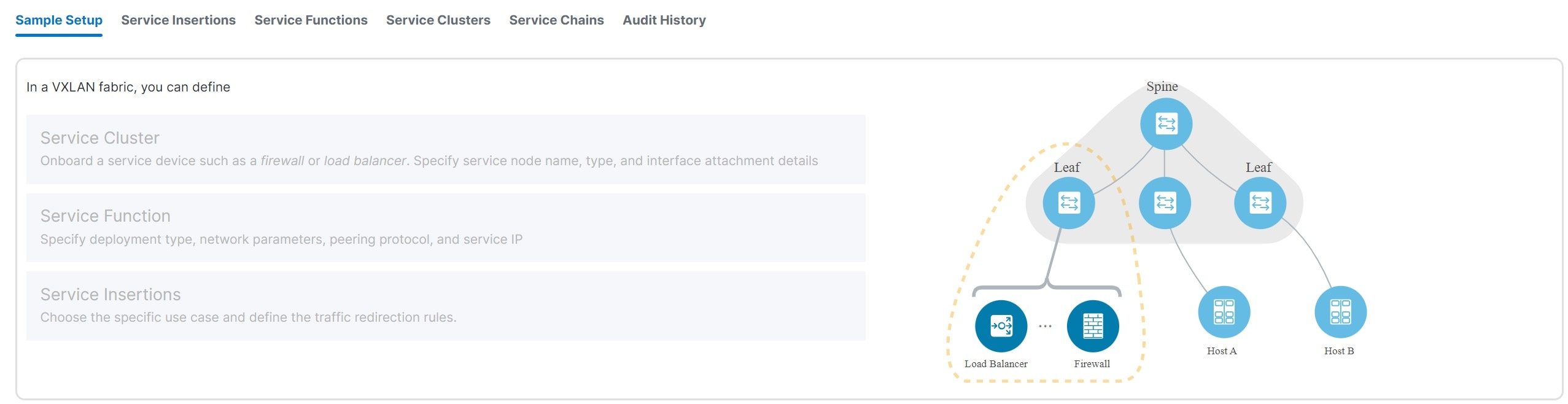
These tabs are shown on the L4-L7 services page.
-
Sample Setup — Shows an example Layer 4 to Layer 7 services setup.
-
Insertions — Shows the Layer 4 to Layer 7 service insertions that you have configured in Nexus Dashboard.
-
Functions — Shows the Layer 4 to Layer 7 service functions that you have configured in Nexus Dashboard.
-
Clusters — Shows the Layer 4 to Layer 7 service clusters that you have configured in Nexus Dashboard.
-
Chains — Shows the Layer 4 to Layer 7 service chains that you have configured in Nexus Dashboard.
Navigate to service insertions
Use service insertions to choose specific use cases and define traffic redirection rules.
-
Navigate to L4-L7 Services for your VXLAN EVPN fabric.
-
Click Manage > Fabrics.
-
Click the VXLAN EVPN fabric where you want to configure service insertions.
-
Click Segmentation and security.
-
Click L4-7 services.
-
-
In the L4-7 services page, click Insertions.
The Insertions page appears. You can perform either of these actions next:
View service insertion information
-
Review the information provided on the Insertions page.
The Insertions page shows information on already-configured service insertions.
-
Perform any of the following actions on the Insertions page.
-
Click Create insertion to create a new insertion. See Add a service insertion for more information.
-
Use the Actions drop-down to work with existing insertions.
This table describes the action items that are available in the Actions drop-down list.
Insertions Actions and Description Action Item Description Edit
Allows you to view or edit the selected service insertion parameters.
-
To edit the service insertion information, check the check box next to the service insertion name that you want to edit and choose Edit.
-
On the Edit service insertion page, edit the required values and click Save to apply the changes or click Close to discard the changes.
Attach
Allows you to attach the selected service insertion configuration.
Detach
Allows you to detach the selected service insertion configuration.
Preview
Allows you to preview the selected service insertion configuration before deploying it.
To display the preview, choose the required service insertion and click Preview.
A Preview Service Policy window is displayed.
Select a specific switch, network, or VRF from the respective drop-down lists to display the generated pending configurations for specific switches, networks, and VRFs. Click Close to close the window.
Delete
Allows you to delete a selected service insertion. You can select multiple service insertion entries and delete them at the same time.
-
To delete a service insertion, check the check box next to the service insertion that you want to delete and choose Delete.
A warning message appears asking whether you want to delete the service insertions.
-
Click Confirm to delete or click Cancel to retain the service insertion.
A message appears that the selected service insertions are deleted successfully.
-
-
Add a service insertion
-
Click Create Insertion.
The Add Service Insertion page displays.
-
Enter a name for the service insertion in the Service Insertion Name field.
The service insertion name can have an alphanumeric, underscore, or dash character.
-
In the Use Case field, choose from these types of service insertion use cases:
-
Redirect to Service Chain — Selective traffic redirection, load-balancing, and service chaining with health monitoring.
-
Service as Default Gateway — Intra-VRF or intra-tenant redirection with the service as the default gateway.
-
Perimeter Service — Inter-VRF or inter-tenant service redirection.
-
Legacy Service Redirection — Selective traffic redirection with legacy PBR workflow (no health monitoring).
-
Route Peering Service — A new use case introduced in release 4.1.1. Service for route peering between the service function and the fabric.
-
Redirect to Service Chain
This service insertion use case configures selective traffic redirection, load-balancing, and service chaining with health monitoring.
-
Enter the necessary information to configure a service insertion with this use case:
Field
Description
Traffic Source VRF
Choose an existing traffic source VRF to associate with this service insertion use case, or click +Create VRF to create a new VRF. For more information, see Working with VRFs.
Traffic Destination VRF
Choose an existing traffic destination VRF to associate with this service insertion use case, or click +Create VRF to create a new VRF. For more information, see Working with VRFs.
Detach/Attach
Toggle the switch to detach or attach.
Direction
Choose the direction for this service insertion use case. Options are:
-
Bidirectional
-
Forward
-
Reverse
Enable Statistics
Check the check box to enable statistics for this service insertion use case.
-
-
In the Traffic Flow Redirects area, click + Add Traffic Flow Redirect and enter the necessary information:
Field
Description
Match ACL Name
Choose an already-configured access control list (ACL) from the drop-down list, or click +Create ACL to create a new access control list. For more information, see ACL templates.
Match Action
Choose the appropriate ACL match action. Options are:
-
Redirect
-
Drop
-
Exclude
You can have only one Drop and one Exclude in the service insertion for a service chain.
Service Chain Name
Choose an already-configured service chain from the drop-down list, or click +Create Service Chain to create a new service chain. For more information, see Add a service chain.
Details
Provides details of the traffic flow redirect that you configured. If additional details are configured but are not shown in the Details area, click the pencil icon (edit), then click View Details under the Service Chain Name entry.
-
-
When you have completed the configuration for this traffic flow redirect, click the check mark at the end of the row to accept the values that you entered.
Repeat these steps to configure additional traffic flow redirects.
-
On the Networks tab, click + Add Row and enter the necessary information.
Field
Description
Source Network
The source and destination network fields are auto-populated based on the ACL entries in the selected or newly created ACL. You can override the system auto-populated source and/or destination network.
If you want to override the system auto-populated source and/or destination network, choose an already-configured source and/or destination network from the drop-down list, or click + Create Network to create a new network. For more information, see Working with networks.
The source and destination network cannot be the same for the redirect to service chain use case.
Destination Network
Specify the destination network.
Source Switch(Interfaces)
Choose the source switch interfaces, if necessary.
Destination Switch(Interfaces)
Choose the destination switch interfaces, if necessary.
-
When you have completed the configuration for this network, click the check mark at the end of the row to accept the values that you entered.
-
Repeat these steps to configure additional networks.
-
Click Save after you have entered the necessary information to add a service insertion with this use case.
You are returned to the Fabric Overview page, with Services > Service Insertions selected.
-
In the list of configured service insertions that is displayed, perform any of these actions:
-
Click the down arrow at the upper right corner of the area for a service insertion to see additional information on that service insertion.
-
Choose a service insertion and click Actions > Edit to edit that service insertion configuration.
-
Choose a service insertion and click Actions > Attach to attach that service insertion configuration.
-
Choose a service insertion and click Actions > Detach to detach that service insertion configuration.
-
Choose a service insertion and click Actions > Delete to delete that service insertion.
-
Click View Details in the Statistics/Probe Details area to view the statistics for that service insertion. For more information, see View service insertion stats details.
-
Service as Default Gateway
This service insertion use case configures intra-VRF or intra-tenant redirection with the service as the default gateway.
-
Enter the necessary information to configure a service insertion with this use case.
Field
Description
Outside VRF Name
Choose an existing outside VRF to associate with this service insertion use case, or click +Create VRF to create a new VRF. For more information, see Working with VRFs.
Detach/Attach
Toggle the switch to detach or attach.
Service Function
The service function pull-down list is pre-populated with service functions that have an N Arms connectivity mode and have a matched outside VRF. Choose an existing service function to associate with this service insertion use case, or click +Create Service Function to create a new service function. For more information, see Add a service function.
-
In the Inside L2 Network area, click + Add L2 Network, then choose an existing Layer 2 network to associate with this service insertion use case, or click +Create Network to create a new Layer 2 network. For more information, see Working with networks.
-
When you have completed the configuration for the inside Layer 2 network, click the check mark at the end of the row to accept the values that you entered.
Repeat these steps to configure additional inside Layer 2 networks, if necessary.
-
Click Save after you have entered the necessary information to add a service insertion with this use case.
You are returned to the L4-L7 Services page, with Insertions selected.
-
In the list of configured service insertions that is displayed, perform any of these actions:
-
Click the down arrow at the upper right corner of the area for a service insertion to see additional information on that service insertion.
-
Choose a service insertion and click Actions > Edit to edit that service insertion configuration.
-
Choose a service insertion and click Actions > Attach to attach that service insertion configuration.
-
Choose a service insertion and click Actions > Detach to detach that service insertion configuration.
-
Choose a service insertion and click Actions > Delete to delete that service insertion.
-
Click View Details in the Statistics/Probe Details area to view the statistics for that service insertion. For more information, see View service insertion stats details.
-
Perimeter Service
This service insertion use case configures inter-VRF or inter-tenant service redirection.
-
Enter the necessary information to configure a service insertion with this use case.
Field
Description
Outside VRF Name
Choose an existing outside VRF to associate with this service insertion use case, or click +Create VRF to create a new VRF. For more information, see Working with VRFs.
Inside VRF Name
Choose an existing inside VRF to associate with this service insertion use case, or click +Create VRF to create a new VRF. For more information, see Working with VRFs.
Detach/Attach
Toggle the switch to detach or attach.
Service Function
The service function pull-list is pre-populated with service functions that have a matched outside and inside VRF. Choose an existing service function to associate with this service insertion use case, or click +Create Service Function to create a new service function. For more information, see Add a service function.
-
Click Save after you have entered the necessary information to add a service insertion with this use case.
You are returned to the L4-L7 Services page, with Insertions selected.
-
In the list of configured service insertions that is displayed, perform any of these actions:
-
Click the down arrow at the upper right corner of the area for a service insertion to see additional information on that service insertion.
-
Choose a service insertion and click Actions > Edit to edit that service insertion configuration.
-
Choose a service insertion and click Actions > Attach to attach that service insertion configuration.
-
Choose a service insertion and click Actions > Detach to detach that service insertion configuration.
-
Choose a service insertion and click Actions > Delete to delete that service insertion.
-
Click View Details in the Statistics/Probe Details area to view the statistics for that service insertion. For more information, see View service insertion stats details.
-
Legacy Service Redirection
This service insertion use case configures selective traffic redirection with a legacy PBR workflow. Health monitoring is not configured with this use case.
-
Enter the necessary information to configure a service insertion with this use case:
Field
Description
VRF Name
Choose a VRF to associate with this service insertion use case, or click +Create VRF to create a new VRF. For more information, see Working with VRFs.
Detach/Attach
Toggle the switch to detach or attach.
Direction
Choose the direction for this service insertion use case. Options are:
-
Bidirectional
-
Forward
-
Reverse
Enable Statistics
Check the check box to enable statistics for this service insertion use case.
Matched ACL Name
Choose an already-configured access control list (ACL) from the drop-down list, or click +Create ACL to create a new access control list. For more information, see ACL templates.
Service Function
The Service Function drop-down list is pre-populated with service functions that have a matched VRF and do not have a probe defined. Choose an existing service function to associate with this service insertion use case, or click +Create Service Function to create a new service function. For more information, see Add a service function.
Single Service Redirect Template
Choose the service_pbr service redirect template. For more information, see Service insertion template.
-
-
Click the General Parameters tab and enter the necessary information.
Field
Description
Route Map Action
Choose an action from the drop-down list. The options are permit or deny. If you select permit, the matched traffic is redirected based on the next-hop option and the defined policy. If you select deny, the traffic is routed based on the routing table rules.
Next Hop Option
Specify an option for the next-hop. The options are none, drop-on-fail, and drop. If you select none, the matched traffic is redirected based on the defined PBR rules. If you select drop-on-fail, the matched traffic is dropped if the specified next hop is not reachable. If you select drop, the matched traffic is dropped.
-
Click the Advanced tab and enter the necessary information.
All the values in the Advanced tab are automatically generated unless otherwise specified.
Field
Description
ACL Name
Specify a name for the generated access control list (ACL). If not specified, this is auto-generated.
ACL Name for reversed traffic
Specify a name for the ACL that is generated for reversed traffic. If not specified, this is auto-generated.
Route map match number
Specify a route map match number. A valid value ranges from 1 to 65535. If not specified, a route map match sequence number will be retrieved from the predefined resource pool. This number is associated with the name of the ACL.
Route map match number for reversed traffic
Specify a route map match number for reversed traffic. A valid value ranges from 1 to 65535. If not specified, a route map match sequence number will be retrieved from the predefined resource pool. This number is associated with the name of the ACL that has been generated for reversed traffic.
-
In the Networks area, click + Add Row and enter the necessary information:
Field
Description
Source Network
Choose an already-configured source network from the drop-down list, or click +Create Network to create a new network. For more information, see Working with networks.
Destination Network
Choose an already-configured destination network from the drop-down list, or click +Create Network to create a new network. For more information, see Working with networks.
Source Switch(Interfaces)
Choose the source switch interfaces, if necessary.
Destination Switch(Interfaces)
Choose the destination switch interfaces, if necessary.
-
When you have completed the configuration for this network, click the check mark at the end of the row to accept the values that you entered.
Repeat these steps to configure additional networks.
-
Click Save after you have entered the necessary information to add a service insertion with this use case.
You are returned to the Fabric Overview page, with Services > Service Insertions selected.
-
In the list of configured service insertions that is displayed, perform any of these actions:
-
Click the down arrow at the upper right corner of the area for a service insertion to see additional information on that service insertion.
-
Choose a service insertion and click Actions > Edit to edit that service insertion configuration.
-
Choose a service insertion and click Actions > Attach to attach that service insertion configuration.
-
Choose a service insertion and click Actions > Detach to detach that service insertion configuration.
-
Choose a service insertion and click Actions > Delete to delete that service insertion.
-
Click View Details in the Statistics/Probe Details area to view the statistics for that service insertion. For more information, see View service insertion stats details.
-
Route Peering Service
This service insertion use case configures a service for route peering between the service function and the fabric.
-
Enter the necessary information to configure a service insertion with this use case.
Field
Description
First Arm VRF
Choose an existing first arm VRF to associate with this service insertion use case, or click +Create VRF to create a new VRF. For more information, see Working with VRFs.
Second Arm VRF
If you want a two-arm deployment mode, choose an existing second arm VRF to associate with this service insertion use case, or click +Create VRF to create a new VRF. For more information, see Working with VRFs. Leave this field empty if you want a one-arm deployment mode.
Detach/Attach
Toggle the switch to detach or attach.
Service Function
The service function pull-list is pre-populated with service functions that have a matched outside and inside VRF. Choose an existing service function to associate with this service insertion use case, or click +Create Service Function to create a new service function. For more information, see Add a service function.
-
Click Save after you have entered the necessary information to add a service insertion with this use case.
You are returned to the L4-L7 Services page, with Insertions selected.
-
In the list of configured service insertions that is displayed, perform any of these actions:
-
Click the down arrow at the upper right corner of the area for a service insertion to see additional information on that service insertion.
-
Choose a service insertion and click Actions > Edit to edit that service insertion configuration.
-
Choose a service insertion and click Actions > Attach to attach that service insertion configuration.
-
Choose a service insertion and click Actions > Detach to detach that service insertion configuration.
-
Choose a service insertion and click Actions > Delete to delete that service insertion.
-
Click View Details in the Statistics/Probe Details area to view the statistics for that service insertion. For more information, see View service insertion stats details.
-
View service insertion stats details
After you have completed the configurations for a service insertion, you can view the statistics by clicking View Details in the Statistics/Probe Details area for that service insertion.
-
Click in the Select Date area to change the date range for the statistics.
-
Click in the Switch area to change the switch that you will use for the statistics.
-
Click Clear Stats to clear the statistics.
Navigate to service functions
You use service functions to specify the deployment type, network parameters, peering protocol, and service IP address for your Layer 4 to Layer 7 services.
-
Navigate to L4-L7 Services for your VXLAN EVPN fabric.
-
Click Manage > Fabrics.
-
Click the VXLAN EVPN fabric where you want to configure service insertions.
-
Click Segmentation and security.
-
Click L4-7 services.
-
-
In the L4-7 services page, click Functions.
The Functions page appears. You can perform either of these actions next:
View service function information
-
Review the information provided on the Functions page.
The Functions page shows information on already-configured service functions.
-
Perform any of the following actions on the Functions page.
-
Click Create function to create a new function. See Add a service function for more information.
-
Use the Actions drop-down to work with existing functions.
This table describes the action items that are available in the Actions drop-down list.
Functions Actions and Description Action Item Description Edit
Allows you to view or edit the selected security function parameters.
-
To edit the security function information, check the check box next to the security function name that you want to edit and choose Edit.
-
On the Edit security function page, edit the required values and click Save to apply the changes or click Close to discard the changes.
Delete
Allows you to delete a selected security function. You can select multiple security function entries and delete them at the same time.
-
To delete a security function, check the check box next to the security function that you want to delete and choose Delete.
A warning message appears asking whether you want to delete the service insertions.
-
Click Confirm to delete or click Cancel to retain the security function.
A message appears that the selected service insertions are deleted successfully.
-
-
Add a service function
To add a service function:
-
Click Create function.
The Add Service Function page displays.
-
Enter the necessary information to add a service function.
Field
Description
Type
Choose from these types of service clusters:
-
Firewall
-
Load Balancer
-
Virtual Networking Function
-
Other
Service Function Name
Enter a name for the service cluster. The name can have alphanumeric, underscore, or dash characters.
Connectivity Mode
Choose the connectivity mode:
-
One Arm
-
Two Arm
-
N Arms
Service VRF
Displayed in these situations:
-
Type — Firewall, Load Balancer, Virtual Networking Function, and Other
-
Connectivity Mode — One Arm
Choose an existing VRF to associate with this service function, or click +Create VRF to create a new VRF. See Working with VRFs for more information.
First Arm VRF
Displays in these situations:
-
Type — Load Balancer, Virtual Networking Function
-
Connectivity Mode — Two Arm, N Arms
Choose an existing VRF to associate with this service function, or click +Create VRF to create a new VRF. See Working with VRFs for more information.
Second Arm VRF
Displays in these situations:
-
Type — Load Balancer, Virtual Networking Function
-
Connectivity Mode — Two Arm
Choose an existing VRF to associate with this service function, or click +Create VRF to create a new VRF. See Working with VRFs for more information.
Outside VRF
Displays in these situations:
-
Type — Firewall
-
Connectivity Mode — Two Arm, N Arms
Choose an existing VRF to associate with this service function, or click +Create VRF to create a new VRF. See Working with VRFs for more information.
Inside VRF
Displays in these situations:
-
Type — Firewall
-
Connectivity Mode — Two Arm
Choose an existing VRF to associate with this service function, or click +Create VRF to create a new VRF. See Working with VRFs for more information.
-
If you select the same VRF for both the Outside VRF and the Inside VRF, then an intra-tenant firewall is configured.
-
If you select different VRFs for the Outside VRF and the Inside VRF, then an inter-tenant firewall is configured.
-
-
Click + Add Service Cluster Logical Connectivity.
The Add Service Cluster Logical Connectivity page appears.
-
Enter the necessary information to add service cluster logical connectivity.
Field
Description
Service Cluster Name
Select an already-configured service cluster, or click Add Service Cluster to create a new one. See Add a service cluster for more information.
IPv4 and/or IPv6
Choose from these options:
-
IPv4
-
IPv6
-
IPv4 and IPv6
These fields vary, depending on the connectivity mode that you chose:
-
-
If you chose One Arm in the Connectivity Mode field, these fields appear:
Field
Description
Service IPv4
Enter the IPv4 and/or IPv6 service addresses.
Service IPv6
Enter the IPv6 service address.
Service Network
Choose an existing service network to associate with this service function, or click +Add Service Network to create a new service network. See Working with networks for more information.
Probe
Probe does not apply to an inter-tenant firewall. Choose an existing probe to associate with this service function, or click +Add Probe to create a new probe. See Probe templates for more information.
Peering Option
Choose the appropriate peering option to associate with this service function. Note that some peering options might not be available, depending on the previous configurations that you made.
-
Static
-
eBGP
-
Connected — Choose this peering option if you already have your routing in place. Intra-tenant firewalls only have Connected as the peering option.
Peering Configuration
-
If you are adding a service function in a fabric (not a Multi-Site Domain), then choose the appropriate peering configuration to associate with this service function, or click +Add Peering Configuration to create a new peering configuration. For more information, see Service function route templates.
-
If you are adding a service function in a Multi-Site Domain, then make the following configurations:
-
In the Switch Name field, determine how you want to peer the service node to the MSD. Choose the appropriate switch from the drop-down list in the Switch Name field.
-
The service switch, which the service node is attached to, is indicated with an asterisk.
-
If you see a single-switch option in the Switch Name field (for example, leaf1-v), that means that this is a single, standalone switch.
-
If you see a dual-switch option in this field (for example, bgw1-v ~ bgw2-v), that means that this is a vPC pair.
-
If you chose eBGP in the Peering Option field above, then choose the remote switch used with remote peering. Only the leaf, border, or border gateway switches that are not local to the service cluster are provided as options for this field. See Remote peering for more information.
-
-
In the Peering Configuration field, choose the appropriate peering configuration to associate with this service function, or click +Add Peering Configuration to create a new peering configuration. For more information, see Service function route templates.
-
-
-
If you chose Two Arm in the Connectivity Mode field, these fields appear:
Inside and Outside appear as qualifiers for the service networks if you chose Firewall as the service function type, whereas First-Arm and Second-Arm appear as qualifiers for the service networks if you chose Load Balancer or Virtual Networking Function as the service function type.
Field
Description
Outside/First-Arm Service IPv4
Enter the IPv4 and/or IPv6 outside service addresses.
Outside/First-Arm Service IPv6
Enter the IPv6 service address.
Outside/First-Arm Service Network
Choose an existing outside service network to associate with this service function, or click +Add Service Network to create a new outside service network.
Probe
Probe does not apply to an inter-tenant firewall. Choose an existing probe to associate with this service function, or click +Add Probe to create a new probe. For more information, see Probe templates.
Peering Option
Choose the appropriate peering option to associate with this service function. Note that some peering options might not be available, depending on the previous configurations that you made.
-
Static
-
eBGP
-
Connected — Choose this peering option if you already have your routing in place. Intra-tenant firewalls have only Connected as the peering option.
Peering Configuration
-
If you are adding a service function in a fabric (not a Multi-Site Domain), then choose the appropriate peering configuration to associate with this service function, or click +Add Peering Configuration to create a new peering configuration. For more information, see Service function route templates.
-
If you are adding a service function in a Multi-Site Domain, then make the following configurations:
-
In the Switch Name field, determine how you want to peer the service node to the fabric. Choose the appropriate switch from the drop-down list in the Switch Name field.
-
The service switch, which the service node is attached to, is indicated with an asterisk.
-
If you see a single-switch option in the Switch Name field (for example, leaf1-v), that means that this is a single, standalone switch.
-
If you see a dual-switch option in this field (for example, bgw1-v ~ bgw2-v), that means that this is a vPC pair.
-
If you chose eBGP in the Peering Option field above, then choose the remote switch used with remote peering. Only the leaf, border, or border gateway switches that are not local to the service cluster are provided as options for this field. See Remote peering for more information.
-
-
In the Peering Configuration field, choose the appropriate peering configuration to associate with this service function, or click +Add Peering Configuration to create a new peering configuration. For more information, see Service function route templates.
In the case of a two-arm inter-tenant deployment, two Peering Configuration options are displayed. You can only specify and update the switch names in the first VRF (left) side.
-
Inside/Second-Arm Service IPv4
Enter the IPv4 and/or IPv6 inside service addresses.
Inside/Second-Arm Service IPv6
Enter the IPv6 inside service address.
Inside/Second-Arm Service Network
Choose an existing inside service network to associate with this service function, or click +Add Service Network to create a new inside service network. For more information, see Working with networks.
Probe
Probe does not apply to an inter-tenant firewall. Choose an existing probe to associate with this service function, or click +Add Probe to create a new probe. For more information, see Probe templates.
Peering Option
Choose the appropriate peering option to associate with this service function. Note that some peering options might not be available, depending on the previous configurations that you made.
-
Static
-
eBGP
-
Connected: Select this peering option if you already have your routing in place. Intra-tenant firewall will only have Connected as the peering option.
Peering Configuration
-
If you are adding a service function in a fabric (not a Multi-Site Domain) then choose the appropriate peering configuration to associate with this service function, or click +Add Peering Configuration to create a new peering configuration. For more information, see Service function route templates.
-
If you are adding a service function in a Multi-Site Domain, then make the following configurations:
-
In the Switch Name field, determine how you want to peer the service node to the fabric. Choose the appropriate switch from the drop-down list in the Switch Name field.
-
The service switch, which the service node is attached to, is indicated with an asterisk.
-
If you see a single-switch option in the Switch Name field (for example, leaf1-v), that means that this is a single, standalone switch.
-
If you see a dual-switch option in this field (for example, bgw1-v ~ bgw2-v), that means that this is a vPC pair.
-
If you chose eBGP in the Peering Option field above, then choose the remote switch used with remote peering. Only the leaf, border, or border gateway switches that are not local to the service cluster are provided as options for this field. See Remote peering for more information.
-
-
In the Peering Configuration field, choose the appropriate peering configuration to associate with this service function, or click +Add Peering Configuration to create a new peering configuration. For more information, see Service function route templates.
In the case of a two-arm inter-tenant deployment, two Peering Configuration options are displayed. You can only specify and update the switch names in the first VRF (left) side.
-
-
-
If you chose N Arms in the Connectivity Mode field, these fields appear:
Field
Description
Outside Service IPv4
Enter the IPv4 and/or IPv6 service addresses.
Service IPv6
Enter the IPv6 service address.
Outside Service Network
Choose an existing outside service network to associate with this service function, or click +Add Service Network to create a new service network. For more information, see Working with networks.
Probe
Probe does not apply to an inter-tenant firewall. Choose an existing probe to associate with this service function, or click +Add Probe to create a new probe. For more information, see Probe templates.
Peering Option
Choose the appropriate peering option to associate with this service function. Note that some peering options might not be available, depending on the previous configurations that you made.
-
Static
-
eBGP
-
Connected: Select this peering option if you already have your routing in place. Intra-tenant firewall will only have Connected as the peering option.
Peering Configuration
-
If you are adding a service function in a fabric (not a Multi-Site Domain) then choose the appropriate peering configuration to associate with this service function, or click +Add Peering Configuration to create a new peering configuration. For more information, see Service function route templates.
-
If you are adding a service function in a Multi-Site Domain, then make the following configurations:
-
In the Switch Name field, determine how you want to peer the service node to the fabric. Choose the appropriate switch from the drop-down list in the Switch Name field.
-
The service switch, which the service node is attached to, is indicated with an asterisk.
-
If you see a single-switch option in the Switch Name field (for example, leaf1-v), that means that this is a single, standalone switch.
-
If you see a dual-switch option in this field (for example, bgw1-v ~ bgw2-v), that means that this is a vPC pair.
-
If you chose eBGP in the Peering Option field above, then choose the remote switch used with remote peering. Only the leaf, border, or border gateway switches that are not local to the service cluster are provided as options for this field. See Remote peering for more information.
-
-
In the Peering Configuration field, choose the appropriate peering configuration to associate with this service function, or click +Add Peering Configuration to create a new peering configuration. For more information, see Service function route templates.
In the case of a two-arm inter-tenant deployment, two Peering Configuration options are displayed. You can only specify and update the switch names in the first VRF (left) side.
-
-
-
Click Save after you have entered the necessary information in the Add Service Cluster Logical Connectivity page.
You are returned to the Add Service Function page.
-
Repeat the previous steps to add additional service cluster logical connectivity entries, or click Save on the Add Service Function page to save the service function information.
You are returned to the Fabric Overview page, with Services > Service Functions selected.
In the list of configured service functions that displays, perform any of these actions:
-
Click the down arrow at the upper right corner of the area for a service function to see additional information on that function.
-
Choose a service function and click Actions > Edit to edit that service function configuration. If the updated service function is involved in an enabled or attached service insertion, re-attach that service insertion after the service function update to ensure that the latest changes are reflected in the pending configurations.
-
Choose a service function and click Actions > Delete to delete that service function cluster.
Navigate to service clusters
Service clusters are used to onboard a service device, such as a firewall or load balancer. You specify the service node name, type, and interface attachment details when you add a service cluster.
-
Navigate to L4-L7 Services for your VXLAN EVPN fabric.
-
Click Manage > Fabrics.
-
Click the VXLAN EVPN fabric where you want to configure service insertions.
-
Click Segmentation and security.
-
Click L4-7 services.
-
-
In the L4-7 services page, click Clusters.
The Clusters page appears. You can perform either of these actions next:
View service cluster information
-
Review the information provided on the Clusters page.
The Clusters page shows information on already-configured service clusters.
-
Perform any of the following actions on the Clusters page.
-
Click Create cluster to create a new cluster. See Add a service cluster for more information.
-
Use the Actions drop-down to work with existing clusters.
This table describes the action items that are available in the Actions drop-down list.
Clusters Actions and Description Action Item Description Edit
Allows you to view or edit the selected security cluster parameters.
-
To edit the security cluster information, check the check box next to the security cluster name that you want to edit and choose Edit.
-
On the Edit security cluster page, edit the required values and click Save to apply the changes or click Close to discard the changes.
Delete
Allows you to delete a selected security cluster. You can select multiple security cluster entries and delete them at the same time.
-
To delete a security cluster, check the check box next to the security cluster that you want to delete and choose Delete.
A warning message appears asking whether you want to delete the service insertions.
-
Click Confirm to delete or click Cancel to retain the security cluster.
A message appears that the selected service insertions are deleted successfully.
-
-
Add a service cluster
A service cluster is a logical entity that has a single MAC IP address assigned to it, regardless of the number of service nodes that you have as part of that service cluster.
For example, when you create a service cluster with these procedures, if you choose Standalone in the Node Redundancy field, where you are adding a single node to the service cluster, then that service cluster, with that single node, has one MAC IP address. Similarly, if you choose Active/Standby Cluster in the Node Redundancy field, where you are adding two nodes to the service cluster, then that service cluster also has one MAC IP address, even though two nodes are part of that service cluster.
To add a service cluster:
-
Click Create cluster.
The Add Service Cluster page displays.
-
Enter the necessary information to add a service cluster.
Field
Description
Type
Choose from these types of service clusters:
-
Firewall
-
Load Balancer
-
Virtual Networking Function
-
Other
Service Cluster Name
Enter a name for the service cluster. The name can have alphanumeric, underscore, or dash characters.
Node Redundancy
Choose the node redundancy:
-
Standalone — Applicable if you are adding a single service node in the next step.
-
Active/Standby Cluster — Applicable if you are adding two service nodes in the next step.
-
Active/Active Cluster — Applicable if you are adding more than two service nodes in the next step.
Form Factor
Select Physical or Virtual.
-
-
Click + Add Service Node.
The Add Service Node page appears.
-
Enter a name for the service node in the Service Node Name field.
-
Click + Add Service Node Physical Connectivity.
The Add Service Node Physical Connectivity page appears.
-
Enter the necessary information in the Add Service Node Connectivity page.
Field
Description
Service Node Name
Automatically populated with the service node name that you entered in the previous step.
Service Node Interface
Enter the service node interface. The service node interface is used for visualization.
Service Node Interface Usage
Choose the service node interface usage. The displayed options vary depending on the service cluster type that you chose earlier in this procedure:
-
Firewall:
-
Outside
-
Inside
-
Inside-Outside — You can use this link for both inside and outside.
-
-
Load Balancer, Virtual Networking Function, or Other:
-
First Arm
-
Second Arm
-
First-Second Arm — You can use this link for both first arm and second arm.
-
Attached Fabric/Switch
Choose a fabric, switch, or a switch pair from the list.
Beginning with release 4.1.1, you can attach service nodes that are physically attached to different member fabrics in a Multi-Site Domain, but they can logically be grouped together in a single service cluster.
Switch Interface
Choose the interface from the list.
-
If you selected a vPC pair in the Attached Switch list, the vPC channel displays in the Switch Interface list.
-
Otherwise, the port-channel and interfaces with trunk mode are shown in the Switch Interface list.
Link Template
Choose the serivce_link_trunk, service_link_port_channel_trunk, or the service_link_vpc template from the drop-down list based on the specified attached switch interface type. For more information on template fields, see Service node link templates.
-
-
Click Save after you have entered the necessary information on the Add Service Node Physical Connectivity page.
If you click Save, you are returned to the Add Service Node page.
-
Repeat the previous steps to add another service node interface, or click Save on the Add Service Node page to save the service node information.
You are returned to the Add Service Cluster page.
-
Repeat the previous steps to add another service node, or click Save on the Add Service Cluster page to save the service cluster information.
If you chose Standalone in the Node Redundancy field, the + Add Service Node option is grayed out and not selectable.
If you click Save, you are returned to the Fabric Overview page, with Services > Service Clusters selected.
In the list of configured service clusters that is displayed, perform any of these actions:
-
Click the down arrow at the upper right corner of the area for a service cluster to see additional information on that cluster.
-
Choose a service cluster and click Actions > Edit to edit that service cluster configuration.
-
Choose a service cluster and click Actions > Delete to delete that service cluster.
Navigate to service chains
You use service chains to group and order all of the individual components to insert Layer 4-Layer 7 (L4-L7) service devices in a data center fabric.
-
Navigate to L4-L7 Services for your VXLAN EVPN fabric.
-
Click Manage > Fabrics.
-
Click the VXLAN EVPN fabric where you want to configure service insertions.
-
Click Segmentation and security.
-
Click L4-7 services.
-
-
In the L4-7 services page, click Chains.
The Chains page appears. You can perform either of these actions next:
View service chain information
-
Review the information provided on the Chains page.
The Chains page shows information on already-configured service chains.
-
Perform any of the following actions on the Chains page.
-
Click Create chain to create a new chain. See Add a service chain for more information.
-
Use the Actions drop-down to work with existing chains.
This table describes the action items that are available in the Actions drop-down list.
Chains Actions and Description Action Item Description Edit
Allows you to view or edit the selected security chain parameters.
-
To edit the security chain information, check the check box next to the security chain name that you want to edit and choose Edit.
-
On the Edit security chain page, edit the required values and click Save to apply the changes or click Close to discard the changes.
Delete
Allows you to delete a selected security chain. You can select multiple security chain entries and delete them at the same time.
-
To delete a security chain, check the check box next to the security chain that you want to delete and choose Delete.
A warning message appears asking whether you want to delete the service insertions.
-
Click Confirm to delete or click Cancel to retain the security chain.
A message appears that the selected service insertions are deleted successfully.
-
-
Add a service chain
Add a service chain to configure how traffic is redirected.
To add a service chain:
-
Click Create chain.
The Add Service Chain page displays.
-
Enter a name for the service chain in the Service Chain Name field.
-
Click + Add Service Chain Entries.
-
Enter the necessary information for the service chain entries.
Field
Description
Sequence Number
Enter the sequence number. The lower the number in the sequence, the higher the priority.
For example, if you have two service chain entries configured:
-
Firewall, with a sequence number of 10
-
Load balancer, with a sequence number of 20
Then the firewall, with a sequence number of 10, will be higher priority and will be trigger first in the sequence, followed by the load balancer with a sequence number of 20.
Service Cluster Type
Choose from the following types of service clusters:
-
Firewall
-
Load Balancer
-
Virtual Networking Function
-
Other
VRF
Choose an existing VRF to associate with this service chain, or click + Create VRF to create a new VRF. For more information, see Working with VRFs.
If you are configuring ePBR in a member fabric in a Multi-Site Domain, we recommend that you use a different service VRF for each type of service node, and that the service VRF is different from the tenant VRF.
Service Function
Choose an existing service function to associate with this service chain, or click + Add Service Function to add a new service function. For more information, see Add a service function.
Probe Fail Action
Choose the appropriate probe fail action. Options are:
-
Forward
-
Drop
-
Bypass
-
None
-
-
When you have completed the configuration for this service chain entry, click the check mark at the end of the row to accept the values that you entered.
Repeat these steps to configure additional service chain entries.
-
Click the down arrow next to Service Chain Template to expand that area, then make the necessary configurations in the Service Chain Template area.
For more information, see Service chain templates.
-
Click Save after you have entered the necessary information on the Add Service Chain page.
You are returned to the Fabric Overview page, with Services > Service Chains selected.
In the list of configured service chains that is displayed, perform any of these actions:
-
Choose a service chain and click Actions > Edit to edit that service chain configuration.
-
Choose a service chain and click Actions > Delete to delete that service chain.
View audit history
To view the audit history of the switches and networks that are involved in the selected service insertion or service function, click the Audit History tab on the Services page. The Audit Logs table on the Audit History page displays information about all of the actions that have been performed, such as:
-
Creation of service clusters, service function, service insertions, service chains, probes, routes, and ACLs
-
Deletion of service clusters, service function, service insertions, service chains, probes, routes, and ACLs
-
Update of service clusters, service function, service insertions, service chains, probes, routes, and ACLs
-
Attachment and detachment of service insertions
| Field | Description |
|---|---|
|
User Name |
Specifies the user name of service cluster. |
|
User Role |
Specifies the user role name by whom latest action performed. |
|
Action Taken |
Specifies the latest action performed. |
|
Entity |
Specifies the name of the entity, such as |
|
Status |
Specifies the action status, such as |
|
Time |
Specifies the action time on that node. |
|
More Info |
Click More Info to view detailed information for a selected service cluster. |
To delete older audit reports, click Action > Purge Audit History, then specify the maximum retained dates and confirm deletion. Note that only users with the admin role can delete audit log entries.
Templates
-
ACL templates — Used when adding a service insertion, as part of the redirect to service chain and legacy service redirection use cases.
-
Probe templates — Used in the Add Service Cluster Logical Connectivity page when adding a service function.
-
Service function route templates — Used on the Add Service Cluster Logical Connectivity page when adding a service function.
-
Service chain templates — Used when adding a service chain.
-
Service node link templates — Used when adding a service cluster.
-
Service insertion template — Used when adding a service insertion, as part of the legacy service redirection use case.
ACL templates
You can use the ACL template when adding a service chain for configuring L4-L7 services.
service_acl
The table describes the fields and descriptions for the IP ACL template.
|
Field |
Description |
|
Sequence Number |
Enter the sequence number for the ACL. Valid range: 1 - 4294967295. |
|
Protocol |
Specify the protocol to be used for the ACL. Options are:
|
|
Source IP |
Enter a source IP address for the ACL. This entry can be an IPv4 address, an IPv6 address, or any. |
|
Destination IP |
Enter a destination IP address for the ACL. This entry can be an IPv4 address, an IPv6 address, or any. |
|
Source Port |
Enter the source port number (for example, any or 443). The value in this field is ignored if you selected ip or icmp in the Protocol field. |
|
Destination Port |
Enter the destination port number (for example, any or 443). The value in this field is ignored if you selected ip or icmp in the Protocol field. |
Probe templates
You can use the probe template when adding a service function.
service_endpoint
The table describes the fields and descriptions for the ePBR service endpoint template.
|
Field |
Description |
|
General Parameters |
|
|
Enable Probe |
Check the check box to enable the probe of the (reversed) next hop address. The probe uses loopback fabric-wide settings, as set in the Per VRF Per VTEP Loopback IPv4 Auto-Provisioning and Per VRF Per VTEP Loopback IPv6 Auto-Provisioning fields under Resources for that fabric. For more information, see Editing Data Center VXLAN EVPN Fabric Settings. |
|
Protocol |
Specify the protocol used for the probe. Options are:
|
|
Port Number |
Displayed for input only if the protocol is tcp or udp. Enter the port number for the probe. Valid ranges: 1 - 65535 (recommended range:1025-65534). |
|
User Input for HTTP Probe |
Displayed for input only if the protocol is http. Enter a user input text/filename for an HTTP probe (for example: http://192.168.50.254/index.html). Maximum size: 99. |
|
Advanced |
|
|
Threshold |
Enter the threshold value, in seconds. Valid range: 1 - 60. |
|
Frequency |
Enter the frequency value in seconds. Valid range: 1 - 604800. |
|
Delay Down Change Notification |
Enter the delay down change notification value, in seconds. Valid range: 1 - 180. |
|
Delay Up Change Notification |
Enter the delay up change notification value, in seconds. Valid range: 1 - 180. |
|
Timeout |
Enter the timeout value, in seconds. Valid range: 1 - 604800. |
Service function route templates
These are the service function route templates.
-
service_static_route
-
service_ebgp_route
service_static_route
The table describes the fields and descriptions for the service_static_route template.
|
Field |
Description |
|
Static Routes |
Enter the static routes in the Static Routes field. You can enter one static route per line. |
|
Export Gateway IP |
Click to export the gateway IP (the service node IP) address as the next-hop address. |
service_ebgp_route
The table describes the fields and descriptions for the service_ebgp_route template.
|
Field |
Description |
|
General Parameters |
|
|
Service Node ASN |
Specify the service node ASN, with these minimum and maximum values:
|
|
Service Node IP Address |
Specify the IPv4 address or address with netmask (for example, 1.2.3.4 or 1.2.3.1/24). An IPv4 or IPv6 address is mandatory. |
|
Use Auto-Created Per VRF Per VTEP Loopback |
Check the box to use the automatically-created per VRF per VTEP loopback IP address. Only applicable when the Per VRF Per VTEP Loopback IPv4/IPv6 Auto-Provisioning option is enabled in the fabric setting. |
|
Loopback IP |
Specify the IPv4 address of the loopback on the switch. Loopback IPv4 or IPv6 address is mandatory. |
|
vPC Peer’s Loopback IP |
Specify the IPv4 address of the peer switch’s loopback. The switch with the smaller serial number will take this value. |
|
Export Gateway IP |
Click to export the gateway IP (the service node IP) address as the next-hop address. |
|
Advanced |
|
|
Service Node IPv6 Address |
Specify the IPv6 address of the neighbor. |
|
Loopback IPv6 |
Specify the IPv6 address of the loopback on the switch. |
|
vPC Peer’s Loopback IPv6 |
Specify the IPv6 address of the peer switch’s loopback. |
|
Route-Map TAG |
Specify the route-map tag that is associated with the interface IP. |
|
IPv4 Inbound Route-Map |
Specify the IPv4 inbound route map. No route map is used if this field is left blank. |
|
IPv4 Outbound Route-Map |
Specify the IPv4 outbound route map. If this field is left blank, the system uses |
|
IPv6 Inbound Route-Map |
Specify the IPv6 inbound route map. No route map is used if this field is left blank. |
|
IPv6 Outbound Route-Map |
Specify the IPv6 outbound route map. If this field is left blank, the system uses |
|
Interface Description |
Enter a description for the interface. |
|
Local ASN |
Specify a local ASN to override the system ASN. |
|
Advertise Host Routes |
Choose this option to enable advertisement of /32 and /128 routes to the edge routers. |
|
Enable eBGP Password |
Choose this option to enable the eBGP password. Enabling this option automatically enables the following Inherit eBGP Password from Fabric Settings field. |
|
Inherit eBGP Password from Fabric Settings |
Choose this option to inherit the eBGP password from Fabric Settings. Enabling this option automatically disables the following eBGP Password and eBGP Authentication Key Encryption Type fields. |
|
eBGP Password |
Enabled if you did not enable the Inherit eBGP Password from Fabric Settings field. If enabled, enter the encrypted eBGP password hex string. |
|
eBGP Authentication Key Encryption Type |
Enabled if you did not enable the Inherit eBGP Password from Fabric Settings field. If enabled, enter the BGP key encryption type:
|
|
Enable Interface |
Clear this option to disable the interface. By default, the interface is enabled. |
|
vPC |
|
|
Peering via vPC Peer-Link |
Check this box to configure per-VRF peering through the vPC peer-link. Normally, you might enable the vPC advertise-pip option at the fabric level. Use this Peering via vPC Peer-Link option if you don’t want to have the vPC advertise-pip setting for all of the vPC pairs in the fabric. This option is also needed if you have a shared border deployment with Layer 4 to Layer 7 devices. The remaining fields in this tab become available only if you enable the Peering via vPC Peer-Link option. |
|
Source IP Address/Netmask |
Specify the source IP address and netmask. For example, 192.168.10.1/30. |
|
Destination IP Address |
Specify the destination IP address. For example, 192.168.10.2. The switch with the smaller serial number will take this value. |
|
Source IPv6 Address/Prefix |
Specify the source IPv6 address and netmask. For example, 2001:db9::1/120. |
|
Destination IPv6 Address |
Specify the destination IPv6 address. For example, 2001:db9::10. The switch with the smaller serial number will take this value. |
|
VLAN for Peering Between vPC Peers |
Enter a value for the VLAN peering between vPCs (minimum: 2, maximum: 4094). If no value is specified in this field, the VLAN ID is automatically assigned from the VLAN pool shown in the vPC Peer Link VLAN Range field on the vPC tab. For more information, see Editing Data Center VXLAN EVPN Fabric Settings. |
Service chain templates
You can use the service chain template when adding a service chain.
service_epbr
The table describes the fields and descriptions for the service_epbr template.
|
Field |
Description |
|
Hashing Method |
Choose the load balance method. Valid options are:
|
|
Hashing Bucket |
Enter the buckets for traffic distribution, in powers of 2. Max: 256. |
Service node link templates
These are the service node link templates:
-
service_link_trunk
-
service_link_port_channel_trunk
-
service_link_vpc
service_link_trunk
The table describes the fields and descriptions for the service_link_trunk template.
|
Field |
Description |
|
General Parameters |
|
|
MTU |
Specifies the MTU for the interface. By default, this is set to jumbo. |
|
SPEED |
Specifies the speed of the interface. By default, this is set to Auto. You can change it to different supported speeds as required. |
|
Trunk Allowed VLANs |
Specify none, all, or VLAN ranges. By default, none is specified. |
|
Enable BPDU Guard |
Specify an option from the drop-down list. The available options are true, false, or no. By default, no is specified. |
|
Enable Port Type Fast |
Check this option to enable spanning tree edge port behavior. By default, this is enabled. |
|
Enable Interface |
Clear the check box to disable the interface. By default, the interface is enabled. |
|
Advanced |
|
|
Source Interface Description |
Enter a description for the source interface. |
|
Destination Interface Description |
Enter a description for the destination interface. |
|
Source Interface Freeform Config |
Enter any addition CLI for the source interface. |
|
Destination Interface Freeform Config |
Enter any addition CLI for the destination interface. |
service_link_port_channel_trunk
The table describes the fields and descriptions for the service_link_port_channel_trunk template.
|
Field |
Description |
|
Port Channel Mode |
Select a port channel mode from the drop-down list. By default, active is specified. |
|
Enable BPDU Guard |
Specify an option from the drop-down list. The available options are true, false, or no. |
|
MTU |
Specifies the MTU for the interface. By default, this is set to jumbo. |
|
Trunk Allowed VLANs |
Specify none, all, or VLAN ranges. By default, none is specified. |
|
Port Channel Description |
Enter a description for the port channel. |
|
Freeform Config |
Specify the required freeform configuration CLIs. |
|
Enable Port Type Fast |
Check this option to enable spanning tree edge port behavior. By default, this is enabled. |
|
Enable Port Channel |
Check this option to enable the port channel. By default, this is enabled. |
service_link_vpc
The service_link_vpc template has no specifiable parameters.
Service insertion template
You can use the service_pbr template when adding a service insertion.
service_pbr
The table describes the fields and descriptions for the service_pbr template.
|
Field |
Description |
|
General Parameters |
|
|
Protocol |
Choose a protocol from the drop-down list. The options are icmp, ip, tcp, and udp. |
|
Source Port |
Specify a source port number. If ip or icmp was selected in the Protocol field above, then the value in this Source Port field is ignored. |
|
Destination Port |
Specify a destination port number. If ip or icmp was selected in the Protocol field above, then the value in this Destination Port field is ignored. |
|
Advanced |
|
|
Route Map Action |
Choose an action from the drop-down list. The options are permit or deny. If you choose permit, the matched traffic is redirected based on the next-hop option and the defined policy. If you choose deny, the traffic is routed based on the routing table rules. |
|
Next Hop Option |
Specify an option for the next-hop. The options are none, drop-on-fail, and drop.If you select none, the matched traffic is redirected based on the defined PBR rules. If you select drop-on-fail, the matched traffic is dropped if the specified next hop is not reachable. If you select drop, the matched traffic is dropped. |
|
ACL Name |
Specify a name for the generated access control list (ACL). If not specified, this is auto-generated. |
|
ACL name for reversed traffic |
Specify a name for the ACL that is generated for reversed traffic. If not specified, this is auto-generated. |
|
Route map match number |
Specify a route map match number. A valid value ranges from 1 to 65535. If not specified, a route map match sequence number will be retrieved from the predefined resource pool. This number is associated with the name of the ACL. |
|
Route map match number for reversed traffic |
Specify a route map match number for reversed traffic. A valid value ranges from 1 to 65535. If not specified, a route map match sequence number will be retrieved from the predefined resource pool. This number is associated with the name of the ACL that has been generated for reversed traffic. |
You can also customize the L4-L7 templates based on specific requirements.