Features and Use Cases

Stretched VRF

This section gives an overview of the use case. The complete use case configuration procedure is available in the Stretched VRF in Cisco Cloud APIC document.

You can stretch a VRF with intersite contracts between an on-premises Cisco APIC and a Cloud APIC site or between two Cloud APIC sites. In this situation, you would deploy a consistent intersite policy between the two sites' workloads.

Figure 1. Stretched VRF, On-Premises and AWS
Figure 2. Stretched VRF, On-Premises and Azure
Figure 3. Stretched VRF, Multi-Cloud

Stretched EPG

This section gives an overview of the use case. The complete use case configuration procedure is available in the Stretched EPG in Cisco Cloud APIC document.

You can stretch EPGs between an on-premises Cisco APIC site and a Cloud APIC site or between two Cloud APIC sites. Then endpoints of the stretched EPGs, for example App EPG and Web EPG, can communicate using a contract, regardless of the endpoint location. While communication between different EPGs requires a contract, communication between endpoints within the same EPG does not, regardless of whether the endpoints are in the same or different sites.

Figure 4. Stretched EPG, On-Premises and AWS
Figure 5. Stretched EPG, On-Premises and Azure
Figure 6. Stretched EPG, Multi-Cloud

Internet Services for Cloud Workloads

This section gives an overview of the use case. The complete use case configuration procedure is available in the Internet Service for Cisco Cloud APIC Workloads document.

You can configure external connectivity from the internet to the cloud workloads in Cisco Cloud APIC deployments in Amazon Web Services (AWS) or Microsoft Azure clouds. In this case, you configure an external EPG on the Cloud APIC to allow an Internet Gateway in VPC (AWS) and VNET (Azure) and the external connectivity is supported directly from those instead of the Infra VPC or VPN gateway.

Figure 7. Internet Services for AWS
Figure 8. Internet Services for Azure

Shared On-Premises L3Out

This section gives an overview of the use case. The complete use case configuration procedure is available in the Shared On-Premises L3Out for Cisco Cloud APIC Workloads document.

This document describes how to configure an on-premises external connectivity that is shared by a cloud site in a Cisco ACI multi-cloud architecture. The cloud site can be either Amazon Web Services (AWS) or Microsoft Azure or both. In this situation, the endpoints on a cloud site can use the on-premises external connectivity (L3Out) to access networks outside of the ACI architecture and/or the Internet. One example use case is to use an on-premises firewall to enforce certain mandatory security policies for traffic going in and out of a cloud site.

Figure 9. Shared L3Out, On-Premises and AWS
Figure 10. Shared L3Out, On-Premises and Azure

Shared Services

This section gives an overview of the use case. The complete use case configuration procedure is available in the Shared Services in Cisco Cloud APIC document.

You can configure shared services between on-premises Cisco APIC and a Cloud APIC site or between two cloud APIC sites. A sample deployment diagrams below illustrate a few deployment scenarios for shared services, where a Web EPG is consuming DNS service offered by a DNS EPG deployed in another site. In this case, two separate VRFs are created: one for the on-premises sites and one for the cloud site.

Figure 11. Shared Services, On-Premises and AWS
Figure 12. Shared Services, On-Premises and Azure
Figure 13. Shared Services, On-Premises and Multi-Cloud

Alternatively, an on-premises VRF can be stretched into the cloud site. However, if you choose to do that, only a single VRF can be stretched between an on-premises site and a cloud site.

You can use the Cisco ACI Multi-Site Orchestrator to deploy either one of the described scenarios by simply establishing a contract between the DNS EPG and the Web EPG. The routing, forwarding, and policy enforcement is managed automatically by the APICs in each site.

VNet Peering

This section gives an overview of the use case. The complete use case configuration procedure is available in the Configuring VNET Peering for Cloud APIC for Azure document.

Virtual network (VNet) peering enables seamless connection between two Azure Virtual Networks and is Microsoft's recommended way of forwarding data between two VNets. The virtual networks appear as one for connectivity purposes. The traffic between virtual machines uses the Microsoft backbone infrastructure. Like traffic between virtual machines in the same network, traffic is routed through Microsoft's private network only. Peerings are bidirectional.

Peering connections are non-transitive. For example, assume three VNets (A, B, and C), where A is bidirectionally peered with B, and B is with C. This does not mean A and C are peered with each other.

Network traffic between peered virtual networks is private. Traffic between the virtual networks is kept on the Microsoft backbone network. No public Internet, gateways, or encryption is required in the communication between the virtual networks.

The benefits of using virtual network peering include:

  • A low-latency, high-bandwidth connection between resources in different virtual networks.

  • The ability for resources in one virtual network to communicate with resources in a different virtual network.

  • No downtime to resources in either virtual network when creating the peering, or after the peering is created.

  • Much higher traffic throughput compared to IPSec tunnels.

For more information on VNet peering, see the article Virtual network peering in the Documentation section in the Azure website.

Layer 4 to Layer 7 Services in Infra Tenant for Azure Sites

This section gives an overview of the use case. The complete use case configuration procedure is available in the Configuring L4-L7 Services in Infra Tenant for Cisco Cloud APIC document.

This document describes the workflow for Infra tenant configuration of multi-node service graphs with user defined routing (UDR).

Additional information about service graphs in cloud sites, such as specific features and use cases, is available in the Cloud APIC Azure User Guide. The information and procedures provided below are specific to deploying service graphs from Multi-Site Orchestrator.

Service Graphs

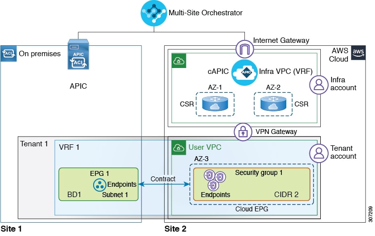
A service graph is used to represent a set of Layer 4 to Layer 7 service devices inserted between two or more EPGs. EPGs can represent your applications running within a cloud (e.g. Cloud EPG), or internet (e.g. Cloud External EPG), or in other sites (e.g. on-premises or remote cloud sites).

A service graph in conjunction with contracts (and filters) is used to specify communication between two EPGs. The cloud APIC automatically derives security rules, such as network security groups (NSG) and application security groups (ASG), and forwarding routes (UDR) based on the policy specified in Contract and Service Graph.

By using a service graph, you can specify the policy once and deploy the service chain within regions or inter-regions. After the graph is configured, the Cloud APIC automatically configures the services according to the service function requirements that are specified in the service graph. The Cloud APIC also automatically configures the network according to the needs of the service function that is specified in the service graph, which does not require any change in the service device. For third-party firewalls, the configuration inside the device is not managed by cloud APIC.

Each time the graph is deployed, Cisco ACI takes care of changing the network configuration to enable the forwarding in the new logical topology.

Service Graph Devices

Multiple service graphs can be specified to represent different traffic flows or topologies. A service graph represents the network using the following elements:

  • Service Graph Nodes—A node represents a function that is applied to the traffic, such as a load balancer. A function within the service graph may require one or more parameters and have one or more connectors.

  • Connectors—A connector enables input and output from a node.

Following combinations are possible with service graphs:

  • Same device can be used in multiple service graphs.

  • Same service graph can be used between multiple consumer and provider EPGs.

The following service graph devices are supported:

  • Azure Application Load Balancers (ALB)

  • Azure Network Load Balancers (NLB)

  • Unmanaged third-party firewall devices

Azure User Defined Routing (UDR)

Release 5.0(2) of Cloud APIC adds support for user-defined routing (UDR) for Azure Cloud APIC sites, similar to the policy-based redirect (PBR) feature available for the on-premises sites. The UDR feature is configured using the Redirect option during Service Graph node configuration.

With redirect, policies are used to redirect traffic through specific service devices, where service devices can be deployed as a Network Load Balancer or a third-party firewall. This traffic isn't necessarily destined for the service device as part of the standard consumer-to-provider configuration; rather, you would configure the consumer-to-provider traffic as you normally would, and you would then configure service graphs to redirect that consumer-to-provider traffic to a specific service device.

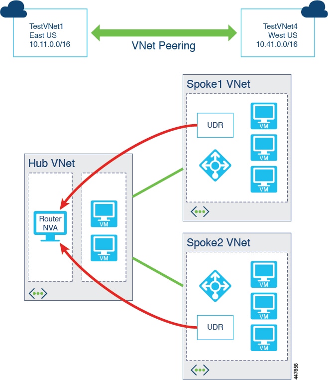
Support for redirect for Cisco Cloud APIC is only available in conjunction with the VNet peering feature, taking advantage of the hub-and-spoke topology used in VNet peering. For more information on the VNet peering feature, see the Configuring VNet Peering for Cloud APIC for Azure document.