Using PowerOn Auto Provisioning

This chapter describes how to deploy and use Power On Auto Provisioning (POAP).

This chapter contains the following sections:

About Power On Auto Provisioning

When a Cisco MDS Series switch with POAP feature boots and does not find the startup configuration, the switch enters POAP mode and checks for a USB device (containing the configuration script file) in USB port 1. If it finds a USB device, it checks the device to see if the device also contains the software image files and the switch configuration file.

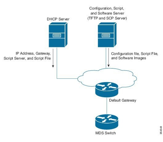
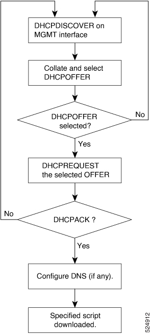
If the switch does not find a USB device in USB port 1, or if the USB device does not contain the required software image files or the switch configuration file, the switch locates a DHCP server and bootstraps itself with the interface IP address, gateway, DNS server IP addresses, IP address of a TFTP server or the URL of an HTTP server and the bootfile name. The switch then obtains the IP address of a TFTP server or the URL of an HTTP server from where it downloads the necessary configuration files.


Note


DHCP information is used during the POAP process only when POAP fails via USB because of the following reasons:

  • USB is not present.

  • Script is not present or script is present with incorrect names.

  • Script execution fails.


POAP Configuration Script

The reference script supplied by Cisco supports the following functionalities:

  • Retrieves switch-specific identifiers, for example, the serial number.

  • Downloads the software images (system and kickstart images) if the files do not already exist on the switch.

  • Installs the software image on the switch, which is then used at the next reboot.

  • Schedules the downloaded configuration to be applied at the next switch reboot.

  • Stores the configuration as startup configuration.

Guidelines and Limitations for POAP Configuration

The POAP configuration guidelines and limitations are as follows:

  • Only FAT32 USB is supported. (The file system on the USB should be FAT32). For Cisco MDS 9700 series switches, POAP is supported only on USB 1 Port.

  • The software image for the Cisco MDS 9000 Series Switches must support POAP.

  • POAP can be initiated on any supported switch by erasing the startup configuration and reloading the switch.

  • POAP does not support provisioning of the switch after it has been configured and is operational. Only auto provisioning of a switch with no startup configuration is supported.

  • Important POAP updates are logged in the syslog and are available from the serial console.

  • Critical POAP errors are logged to the bootflash. The filename format is date-time_poap_PID_[init,1,2].log, where date-time is in the YYYYMMDD_hhmmss format and PID is the process ID.

  • Script logs are saved in the bootflash directory. The filename format is date-time_poap_PID_script.log, where date-time is in the YYYYMMDD_hhmmss format and PID is the process ID.

  • You can configure the format of the script log file. These formats are specified in the script. The template of the script log file has a default format. However, you can choose a different format for the script execution log file.

  • USB script execution logs are saved in the bootflash directory. The filename format is poap.log_usb_MM_DD_HR_MIN, where MM is the current month, DD is the date, HR is the current hour, and MIN is the current minute.

  • The POAP feature does not require a license, and is enabled by default.


    Note


    POAP is not supported through Nexus Dashboard Fabric Controller (NDFC), formally known as Cisco Data Center Network Management (DCNM).


Network Infrastructure Requirements for POAP

When there is no USB device with the required installation files, or the configuration files are not present in the USB, POAP requires the following network infrastructure:

  • A DHCP server to bootstrap the interface IP address, gateway address, and TFTP address.

  • A TFTP, SCP, FTP AND SFTP server that contains the configuration script used to automate the software image installation and configuration process.

  • One or more servers containing the necessary software images and configuration files.

Figure 1. POAP Network Infrastructure


Setting Up the Network Environment to use POAP

The network environment for POAP can be set up with either a USB or a DHCP server.

Using USB

Follow these guidelines when copying software images, the configuration file, and the configuration script into a USB when setting up the network environment for POAP:

  • The POAP configuration script on the USB should be titled poap_script.py.

    • The configuration file with the name conf_<serialnum>.cfg must be present in the USB. To obtain the serial number of the switch, run the show sprom backplane 1 command:

      switch# show sprom backplane 1 
      DISPLAY backplane sprom contents:
      Common block:
       Block Signature : 0xabab
       Block Version   : 3
       Block Length    : 160
       Block Checksum  : 0x128e
       EEPROM Size     : 512
       Block Count     : 6
       FRU Major Type  : 0x6003
       FRU Minor Type  : 0x0
       OEM String      : Cisco Systems, Inc.
       Product Number  : DS-C9148S48PK9
       Serial Number   : JAF17353076
       Part Number     : 73-15809-01
      
      
  • The names of the software images copied to the USB should have standard names and must match the names specified in the POAP script.

    For example, to boot up a Cisco MDS 9396V 64-Gbps 96-Port Fibre Channel with the m9396v-s3ek9-kickstart-mz.9.4.3.bin and m9396v-s3ek9-mz.9.4.3.bin images, ensure that the POAP configuration script (poap_script.py ) has the following information:

    • set m9148s_image_version 9.4.3

    • set m9396v_kickstart_image_src [format m9396v-s3ek9-kickstart-mz.%s.bin $m9396v_image_version]

    • set m9396v_system_image_src [format m9396v-s3ek9-mz.%s.bin $m9396v_image_version]


      Note


      Ensure that the POAP script identifies the switch.


The latest versions are available here:


Note


  • Only FAT32 USB is supported. (The file system on the USB should be FAT32). For Cisco MDS 9700 series switches, POAP is supported only on USB 1 Port.

  • Both the software images and the configuration files should be present in the USB. If no configuration is required, create an empty file named conf_serialnumber.cfg. When the configuration file is empty, the switch reloads the images twice from the USB.


Using a DHCP Server

Before you begin

Before using the POAP script, perform the following actions:

  • Edit the options dictionary at the top of the script to ensure that all relevant options for your setup are included in the script. Do not change the defaults (in the default options function) directly.

  • If you are updating the POAP script, update the MD5 checksum/tftpboot/poap/poap.py as shown using shell commands.

    f=poap_nexus_script.py ; cat $f | sed '/^#md5sum/d' > $f.md5 ; sed -i "s/^#md5sum=.*/#md5sum=\"$(md5sum $f.md5 | sed 's/ .*//')\"/" $f

    Every time the POAP script is updated, re-run the above script to generate a new MD5 checksum, which should then be used to update the POAP script accordingly.

    Let me know if you want it more formal, technical, or casual!

    Example of key update: # md5sum="a9515da3152f222815eca4e7b8a53700"

  • If the device contains a startup configuration, execute a write erase and reload it.


Note


The older 16G platforms continue to support .tcl script.


Procedure

Step 1

Deploy a TFTP server.

Step 2

Update the poap.py script with the following information. The poap.py script is present in the /tftpboot/poap/ folder

  1. Update image file

    The following example shows how to update image file.
    target_system_image = "m9148v-s8ek9-mz.9.4.3.bin" # Fill the target system image here
    target_kickstart_image = "m9148v-s8ek9-kickstart-mz.9.4.3.bin" # Fill the target kickstart image here
  2. Create hybrid-config folder

  3. In the hybrid-config folder, create a text file with the serial number of the switch.

  4. Add the running configuration of the switch to this text file.

Step 3

Ensure you have the following information in the TFTP server:

  • POAP script is added to the /tftpboot/poap

  • The text file with the running configuration of the switch with the correct serial number is added.

Step 4

Deploy a DHCP server.

Step 5

Configure the following parameters in the DHCP server:

  • Enable the DHCP snooping

  • Interface address range

  • Gateway address

  • Add DNS IP address

  • TFTP server's IP address

  • Script file name : /tftpboot/poap/poap.py

  • File path: /tftpboot/poap

Step 6

Reload the switch


The POAP Process

The POAP process involves the following phases:

  1. Power up

  2. USB discovery

  3. DHCP discovery

  4. Script execution

  5. Post-installation reload

Within these phases, other processes and decision points occur. The following illustration shows a POAP process flow:

See Setting Up the Network Environment to use POAP for more information on the POAP process.

Figure 2. The POAP Process

The Power-Up Phase

When you power-up a switch for the first time, it loads the software image that is installed at manufacturing, and only tries to find a configuration file from which to boot. When a configuration file is not found, the POAP mode starts.

During startup, a prompt appears, asking if you want to terminate POAP and continue with the normal setup. You can choose to exit or continue with POAP.


Note


No user intervention is required for POAP to continue. The prompt that asks if you want to terminate POAP remains available until the POAP process is complete.


If you exit POAP mode, you will enter a setup script that allows you to configure the system admin account and perform basic system setup through a guided dialog. If you remain in POAP mode, all front-panel interfaces will be configured with default settings.

The USB Discovery Phase

When the POAP process begins, the switch searches the root directory for the presence of accessible USB devices with the POAP configuration script file (poap_script.py), configuration files, and system and kickstart images.

If the configuration script file is found on a USB device, POAP begins to run the configuration script. If the configuration script file is not found on the USB device, POAP executes DHCP discovery. (When failures occur, the POAP process alternates between USB discovery and DHCP discovery until POAP succeeds or you manually terminate the POAP process.)

If the software image and switch configuration files specified in the configuration script are present, POAP uses those files to install the software and configure the switch. If the software image and switch configuration files are not on the USB device, POAP performs a clean-up operation and starts the DHCP phase from the beginning.

The DHCP Discovery Phase

The switch sends out DHCP discover messages on the management interface that solicits DHCP offers from the DHCP server or servers. (See the following DHCP Discovery Process.) The DHCP client on the Cisco MDS switch uses the switch serial number in the client-identifier option to identify itself to the DHCP server. The DHCP server can use this identifier to send information, such as the IP address and script filename, back to the DHCP client.

The POAP process requires a minimum DHCP lease period of 3600 seconds (1 hour). POAP checks the DHCP lease period. If the DHCP lease period is set to less than 3600 seconds (1 hour), POAP does not complete DHCP negotiation, but enters the USB phase.


Note


To stop the continuous looping process, the POAP process must be terminated manually.


The DHCP discover message also solicits the following options from the DHCP server:

  • TFTP server name or TFTP server address—The DHCP server relays the TFTP server name or TFTP server address to the DHCP client, which uses this information to contact the TFTP server to obtain the script file.

  • Bootfile name—The DHCP server relays the bootfile name to the DHCP client. The DHCP client uses this information to download the script file.

When multiple DHCP offers that meet the requirement are received, an offer is randomly chosen. The device completes the DHCP negotiation (request and acknowledgment) with the selected DHCP server, and the DHCP server assigns an IP address to the switch. If a failure occurs in any of the subsequent steps in the POAP process, the IP address is released back to the DHCP server.

If none of the DHCP offers meet the requirements, the switch does not complete the DHCP negotiation (request and acknowledgment), and no IP address is assigned. However, the POAP process is not terminated because the switch reverts to the USB phase.

Figure 3. DHCP Discovery Process

Script Execution Phase

After the device bootstraps itself using the information in the DHCP acknowledgment, the script file is downloaded from the TFTP server.

The switch runs the configuration script, which downloads and installs the software image and downloads a switch-specific configuration file.

However, the configuration file is not applied to the switch at this point, because the software image that currently runs on the switch might not support all the commands in the configuration file. After the switch reboots, it begins to run the new software image, if any. At that point, the configuration is applied to the switch.


Note


If script execution fails, the DHCP discovery process restarts.


Post-Installation Reload Phase

The switch restarts and applies (replays) the configuration on the upgraded software image. Afterward, the switch copies the running configuration to the startup configuration.

Configuring a Switch Using POAP

Before you begin

Make sure that the requisite network environment is set up to use POAP. For more information, see the Using USB section.

Procedure


Step 1

Install the switch in the network.

Step 2

Power on the switch.

If no configuration file is found, the switch boots in the POAP mode and displays a prompt that asks if you want to terminate POAP and continue with a normal setup.

No entry is required to continue booting in POAP mode.

Step 3

(Optional) To exit POAP mode and enter the normal interactive setup script, enter y (yes).


What to do next

Verify the configuration.

Verifying the Device Configuration

To verify the configuration after bootstrapping the device using POAP, use one of the following commands:

Command

Purpose

show running-config

Displays the running configuration.

show startup-config

Displays the startup configuration.

For detailed information about these commands, see the Cisco MDS 9000 Family Command Reference.