
Install the Power Supply - HF6100-32D
Overview
The switch has two power supply slots that accept AC and DC input power supplies. The power supply modules are field replaceable units (FRUs) and are hot-swappable. The chassis is delivered with one power supply pre-installed in the power supply slot. If only one power supply is ordered, then a blank cover is installed in the empty power supply slot, which must remain installed if a power supply is not installed.
|
Part Number |
PSU Modules |
|---|---|
|
PSU1.4KW-ACPE (default) |
1400-Watts AC Power Module with Port-side Air Exhaust |
|
PSU1.4KW-ACPI (optional) |
1400-Watts AC Power Module with Port-side Air Intake |
|
PSU2KW-ACPI (optional) |
2000-Watts AC Power Module with Port-side Air Intake |
|
PSU2KW-DCPI (optional) |
2000-Watts DC Power Module with Port-side Air Intake |
|
PSU2KW-ACPE (optional) |
2000-Watts AC Power Module with Port-side Air Exhaust |
|
PSU2KW-DCPE (optional) |
2000-Watts DC Power Module with Port-side Air Exhaust |
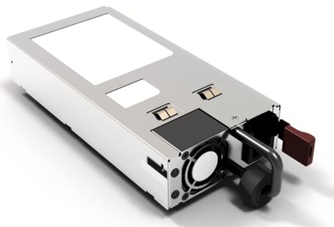
Power supply model
The power supplies can work together in Redundant Mode, in which each power supply operates at approximately 50 percent of its capacity, no greater than 60 percent and no less than 40 percent. If one power supply fails, the other power supply can provide power for the entire system on its own. This is the default and recommended mode.
Power supply modules LED
The AC and DC power supply modules have the following LEDs:
-
Green indicating the power status
-
Red indicating the power supply failure
-
Amber indicating a warning
|
LED |
Status |
Description |
|---|---|---|
|
Unlit |
Off |
No input power. |
|
Green |
Blinking |
AC is present; 3.3 VSB (Voltage Standby) is on. Power supply unit is off. |
|
Solid |
Power supply is functioning normally. |
|
|
Amber |
Blinking |
Warning detected. Power supply continues to operate. High temperature, high power and slow fan conditions. |
|
Red |
Solid |
Power supply failure. This may be due to excessive voltage, excessive current, excessive temperature, output ORING FET fault and fan failure. |
Power supply installation guidelines
-
Use one type of power supply in a switch.
-
The power supply type that is used in the switch depends on the type and configuration of the transceivers installed in it.
-
Do not install a mix of AC and DC power supplies in a switch.
-
The airflow direction must be the same for all power supply and fan modules in the switch.
-
The AC-input power supplies support low-line voltage of 120V (Nominal) and high-line voltage of 220V (Nominal). If you need to change voltage type after installation, disconnect the feed from the power supply before switching the input voltage level.
-
The power supply is already inserted into the chassis.
-
Ensure that the power source is OFF. As an added precaution, place the appropriate safety flag and lockout devices at the source power circuit breaker, or place a piece of adhesive tape over the circuit breaker handle to prevent accidental power restoration while you are working on the circuit.
-
Install the power supply
Step 1 | Ensure that both the PSUs are powered off. | ||
Step 2 | If the power supply is connected to an AC or DC circuit, shut off the circuit at the circuit breaker or PDU. | ||
Step 3 | Insert the new PSU. | ||
Step 4 | Connect the PSU cable. If the power supply is connected to an AC or DC circuit, turn on the circuit at the circuit breaker or PDU source. Wait till the PSU LED color turns green. After replacing the PSU, verify the power using the show environment power command. 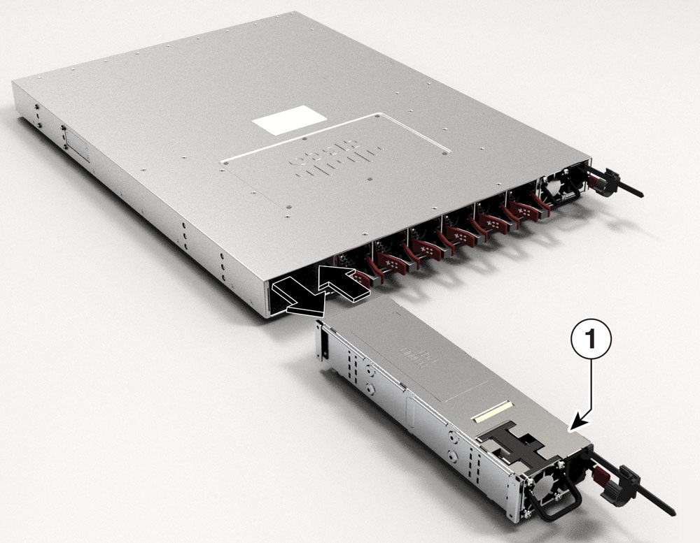
|
Connect to a power source
Each power cable is shipped with mating connectors with one of the connectors on the power socket and the other connector on the front panel of the power supply. You follow the same steps to install the AC-input and DC-input power supplies, but you must ground them differently.
-
AC-input power supply—It is automatically grounded when you connect its power cable to the power supply and the power source.
-
DC-input power supply—You do not connect the power supply directly to the earth ground.
You use one power cord for each power supply to connect the power supply to its power source.
Connect to an AC power source
Step 1 | Prior to connecting the power supply to a power source, ensure that the chassis is properly grounded. |
Step 2 | Plug the power cable into the power supply. |
Step 3 | Plug the other end of the power cable into a power source supplied by the data center.  Note NoteWhen using redundant mode, connect each power supply to a separate power source. |
Step 4 | Verify that the power supply is receiving power by checking that the LED is on and is amber or red. For more information about the power supply LEDs and the on for a couple of seconds. If the LED is flashing amber or conditions that they indicate, see Power Supply LEDs
|
Connect to a DC power source
You can connect the DC power supply directly to one or two DC power sources.
NoteStatement 1003—DC Power Disconnection - To reduce risk of electric shock or personal injury, disconnect DC power before removing or replacing components or performing upgrades.
Step 1 | Prior to connecting the power supply to a power source, ensure that the chassis is properly grounded. |
Step 2 | Plug the DC power cable into the DC power supply. |
Step 3 | Turn off the power at the circuit breakers for the portions of the DC grid power that you are connecting to and verify that all of the LEDs on the DC grid power supplies are off. |
Step 4 | Install the two cables from the DC power cable to a DC power source as follows:
|
Step 5 | Verify that the power supply is receiving power by checking that the LED is on and is amber or red. For more information about the power supply LEDs and the conditions that they indicate, see Power Supply LEDs. |