Install the Fan - HF6100-60L4D
Overview
The switch supports field-replaceable, variable-speed modular fans with default front-to-back airflow. It also supports fan modules with back-to-front airflow. These fan units support Online Insertion and Removal (OIR) for up to 120 seconds. The fan unit is responsible for cooling the entire chassis and interfacing with environmental monitors to trigger alarms when conditions exceed thresholds.
|
Part Number |
PSU Modules |
|---|---|
|
C9500X-FAN-1U-R |
Front to back cooling fan |
|
C9500X-FAN-1U-F |
Back to front cooling fan |
Six individual fan modules are available. The switch can operate with five operational fans and one nonfunctional fan. Any failed fan should be replaced as soon as possible to avoid service interruption due to a second fan fault.
|
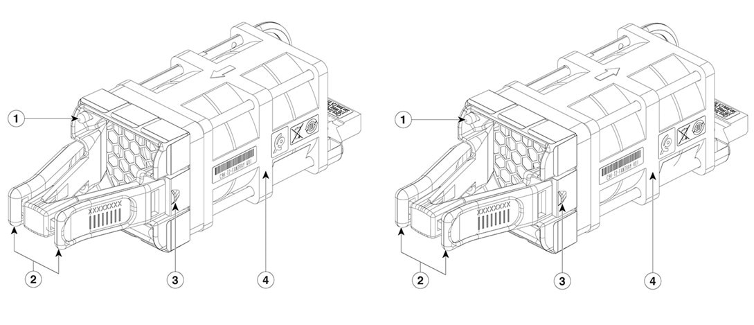
1 |
Fan LED |
3 |
Fan assembly retention latch |
|
2 |
Fan assembly levers C9500X-FAN-1U-R has a red-colored lever C9500X-FAN-1U-F has a blue-colored lever |
4 |
Fan |
Fan installation guidelines
-
For the switch to boot-up, ensure that the when you use C9500X-FAN-1U-R or C9500X-FAN-1U-F modules must at a minimum have 5 fans operating normally.
-
If the switch fails to meet the minimum number of required fans, the switch shuts down automatically to prevent the system from overheating.
-
Each switch contains six field-replaceable fans with variable-speed operating in N+1 redundancy mode.
-
Provides support for front-to-back airflow and back-to-front airflow fans. By default, the switch provides front-to-back airflow fan.
-
-R in the part number indicates reverse airflow (front-to-back) and -F indicates forward airflow (back-to-front).
-
All the fan modules used in the switch must have the same airflow direction.
-
To change the airflow direction in the unit, ensure that you change all the fan modules to the same type of airflow support. For example, to change to forward airflow, replace all the six fans with C9500X-FAN-1U-F. After replacing all the fan modules, power cycle the unit manually.
-
Observe these guidelines when installing a fan module:
-
Do not force the fan module into the slot. This can damage the pins on the switch if they are not aligned with the module.
-
A fan module that is only partially connected to the switch can disrupt the system operation.
-
The switch supports hot swapping of the fan module. You can remove and replace the module without interrupting normal switch operation.
-
All fan modules should be of the same model (C9500X-FAN-1U-R or C9500X-FAN-1U-F). Installation of mixed type of fan modules is not supported.
-
Install a fan
Step 1 | Pinch the fan module release handle and slide the module out.  Note NoteYou should replace the fan module within 5 minutes to avoid overheating the switch. |
Step 2 | Install the fan module in the fan slot, and firmly push it into the slot, applying pressure to the end of the module, not the extraction handles. When correctly inserted, the fan module is flush with the switch rear panel. When the fan is operating, a green LED is on in the top left corner of the fan. 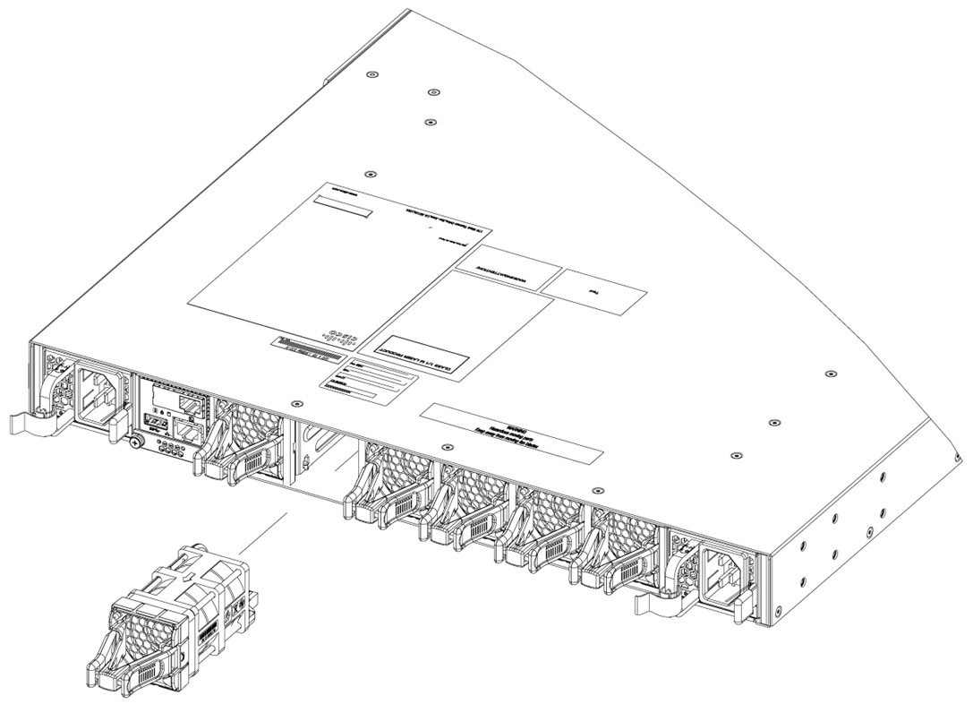
|
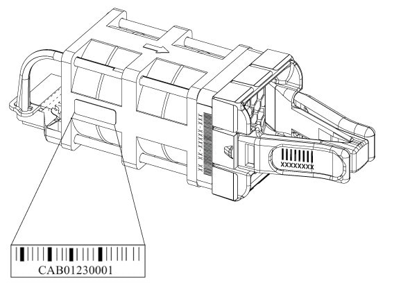
Find the fan module serial number
If you contact Cisco Technical Assistance regarding a fan module, you need to know the fan module serial number. See the following illustration to find the serial number.