Cisco Modeling Labs
OpenStack Clusters
Cisco Modeling Labs OpenStack Clusters Overview
 Note | Cluster installation and operation have only been tested on VMware ESXi and on the Cisco UCS C-series systems. Installation issues may be encountered when using other types of hardware. |
An OpenStack cluster is minimally comprised of one controller and one compute node. Currently, Cisco Modeling Labs clusters can be scaled to a maximum of one controller and four compute nodes.
Cisco Modeling Labs OpenStack Cluster Terminology
|
Term |
Description |
|---|---|
|
Controller |
The primary Cisco Modeling Labs node that includes a complete installation of the Cisco Modeling Labs server software, including full compute, storage, and network functionality and all of the node and container images. |
|
Compute Node |
A node that includes a partial installation of the Cisco Modeling Labs server software that enables it to provide additional compute and networking resources for use by a Cisco Modeling Labs simulation. |
|
Cluster |
A collection of nodes operating in concert. At a minimum, a cluster can be composed of one controller and one compute node. |
|
Cisco Modeling Labs Server Image |
A standard Cisco Modeling Labs installation source (OVA or ISO) that contains the full complement of Cisco Modeling Labs software. |
|
Cisco Modeling Labs Compute Image |
A Cisco Modeling Labs installation source (OVA or ISO) that contains only the Cisco Modeling Labs software necessary to provide compute and networking services. |
When using Cisco Modeling Labs Clusters, the IP address used to reach the User Workspace Management interface and by the Cisco Modeling Labs client will be that of the Controller.
Cisco Modeling Labs OpenStack Clusters Installation Requirements
This section details the hardware and software requirements for successfully deploying a Cisco Modeling Labs cluster.
Cluster-Member Resources
-
Each node must have at least 16GB RAM and 4 CPU or vCPU cores.
-
Each node must support and expose Intel VT-x/EPT extensions.
Note
When using virtual machines, each must be configured to support nested virtualization. This is the default for Cisco Modeling Labs OVA-based installations.
-
Controllers must have at least 250GB of disk or virtual disk space available.
-
Compute nodes must have at least 250GB of disk or virtual disk space available.
-
Each node must have five physical or virtual network interfaces.
Software Requirements
|
Node Type |
Cisco Modeling Labs Software Release |
|---|---|
|
Controller |
CML 1.3 (Build 1.3.286.04) |
|
Compute Node |
CML 1.3 (Build 1.3.286.04) |
Network Time Protocol (NTP)
Note | If you are in a lab or other environment where special requirements apply to the use of NTP, work with your network administrators to ensure that NTP is properly and successfully configured. |
Networking
The Cisco Modeling Labs networks are named Management, Flat, Flat1, SNAT, and INT. These are used for management, Layer-2 and Layer-3 connectivity, and cluster control-plane functions, respectively.
Each of the five required interfaces on a cluster member are connected to these networks in order, as shown.
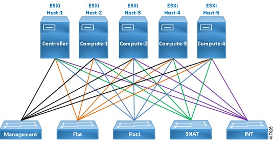
vSphere ESXi Interface Mapping
In vSphere ESXi deployments, multiple port-groups should be used to provide seamless, isolated connectivity for each of the Cisco Modeling Labs networks.
|
Interface |
LAN Switch or VLAN/Port Group |
|---|---|
|
eth0 |
Management (default VM Network) |
|
eth1 |
Flat |
|
eth2 |
Flat1 |
|
eth3 |
SNAT |
|
eth4 |
INT |
Note | The default vSphere ESXi port-group used for the Management network is VM Network but any port-group may be used. Update as required to conform to site-specific configurations. |
Interface Addressing
|
Interface |
Controller |
Compute-1 |
Compute-2 |
Compute-3 |
Compute-4 |
|---|---|---|---|---|---|
|
eth0 |
DHCP or Static |
DHCP or Static |
DHCP or Static |
DHCP or Static |
DHCP or Static |
|
eth1 |
172.16.1.254 |
172.16.1.241 |
172.16.1.242 |
172.16.1.243 |
172.16.1.244 |
|
eth2 |
172.16.2.254 |
172.16.2.241 |
172.16.2.242 |
172.16.2.243 |
172.16.2.244 |
|
eth3 |
172.16.3.254 |
172.16.3.241 |
172.16.3.242 |
172.16.3.243 |
172.16.3.244 |
|
eth4 |
172.16.10.250 |
172.16.10.241 |
172.16.10.242 |
172.16.10.243 |
172.16.10.244 |
 Caution | Do not change the subnet used for the INT network. This must remain on the 172.16.10.0/24 subnet, and the Controller must be assigned 172.16.10.250 on interface eth4. If you are installing a Cisco Modeling Labs OpenStack Cluster alongside an existing standalone Cisco Modeling Labs deployment, you must ensure that they remain isolated using distinct switches, VLANs, or port-groups. Otherwise, conflicts will occur on one or more of the Controller interfaces. |
Controller Deployment
This section details the process involved in controller deployment.
Install Controller Software
The Controller in a Cisco Modeling Labs OpenStack Cluster is adapted from a Cisco Modeling Labs standalone node. As such, complete the installation steps as described in the Cisco Modeling Labs Corporate Edition System Administrator Installation Guide appropriate to your target environment.
Note | Do not proceed until you have fully installed, configured, licensed, and verified your Cisco Modeling Labs node using the installation process for your environment. |
Configuring the Controller
The first series of steps inform the new Cisco Modeling Labs standalone node that it will be operating in a cluster:
Compute Node Deployment
Compute nodes are installed using specialized OVAs or ISOs named compute.n.n.n.ova or compute.n.n.n.iso, respectively. Refer to your license confirmation email for information on how to download these installation sources.
Install Compute Node Software
-
Download the compute node OVAs 1 through 4, depending on the number you wish to deploy.
-
Deploy each of the OVAs to your vCenter/ESXi environment. Important: It is critical that the CML cluster controller and compute-nodes share common port-groups for each of the five network interfaces. These are typically VM Network, Flat, Flat1, SNAT, and INT.
-
Boot the newly deployed compute-node OVA.
Validate Compute Node Operations
Once the compute node has rebooted, continue by validating connectivity to the controller and enabling the Cisco Modeling Labs compute node software using the following steps:
| Step 1 | Login to the
compute node at the IP address recorded during installation using username virl
and password VIRL.
ssh virl@<compute-node-ip-address> | ||
| Step 2 | Ensure that
connectivity to the controller exists by issuing the ping command.
ping 172.16.10.250 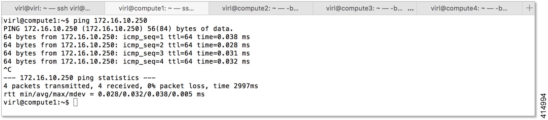
|
Cluster Validation
Once the controller and each compute node has been deployed, you should validate that the cluster is properly configured and operational. To do this, complete the following steps:
| Step 1 | Login to the
controller at the IP address recorded during installation using username virl
and password VIRL.
ssh virl@<compute-node-ip-address> |
| Step 2 | Verify that each
compute node is registered with OpenStack Nova.
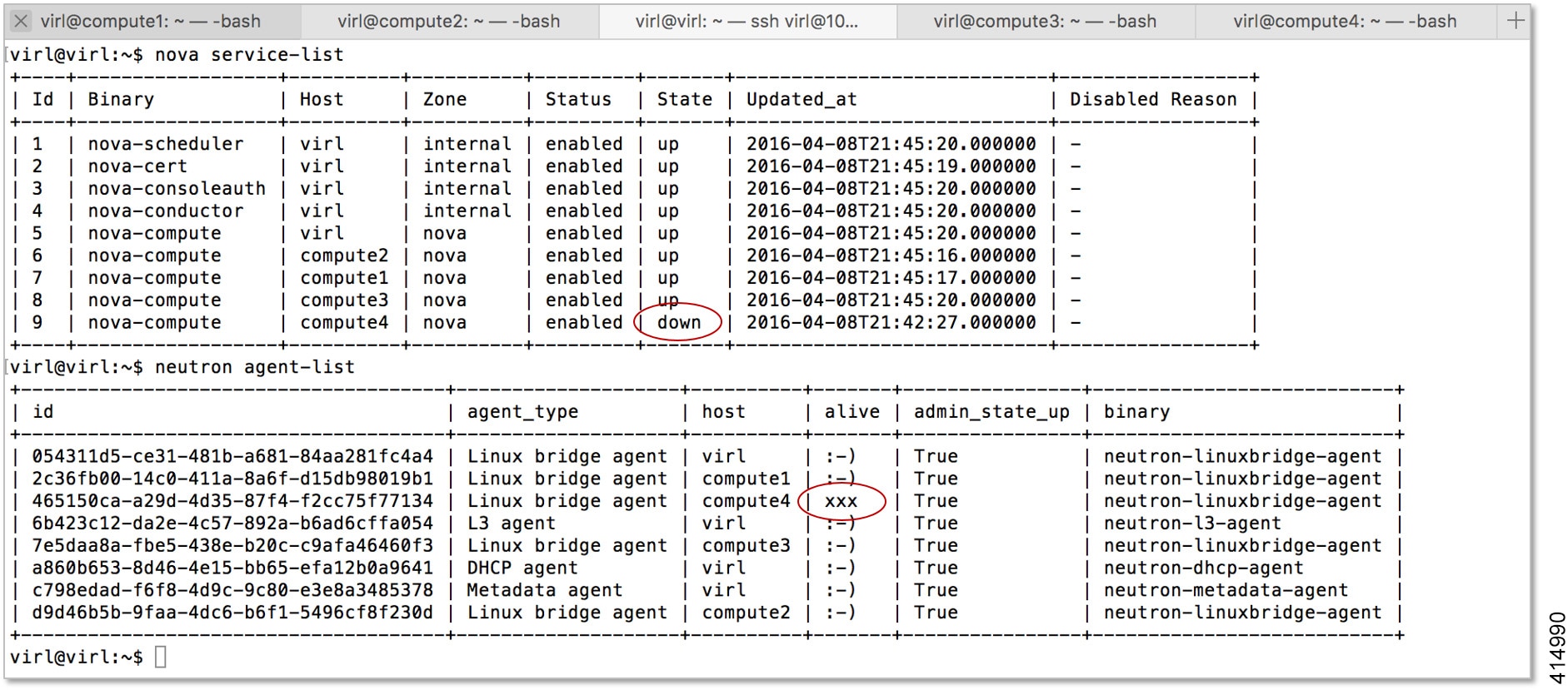
nova service-listIn the following example, there are five nova-compute services registered; one on the controller and another for each compute node that has been deployed. 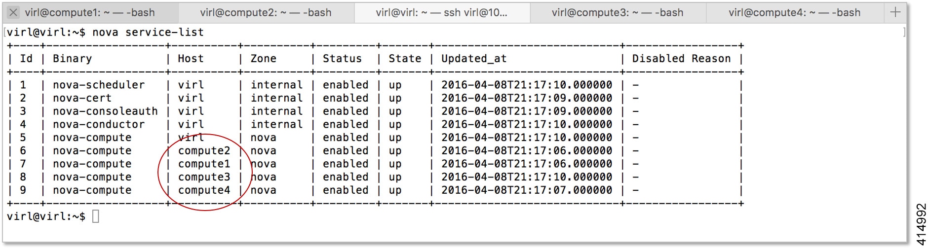 |
| Step 3 | Verify that each
compute node is registered with OpenStack Neutron.
neutron agent-listIn the following example, there are five Linux bridge agents registered; one on the controller and another for each compute node that has been deployed. 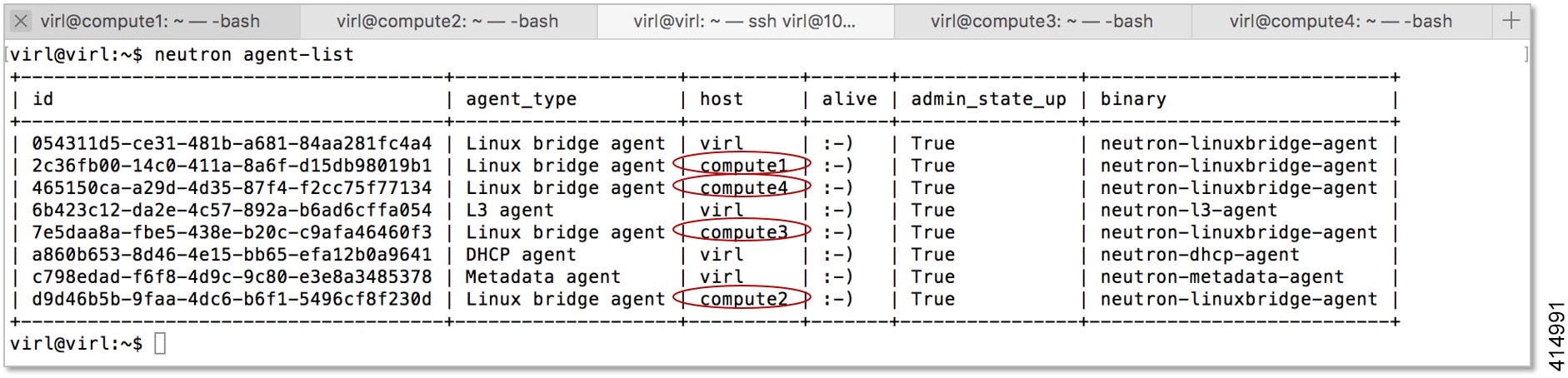 At this point your Cisco Modeling Labs OpenStack Cluster should be fully operational and you should be able to start a Cisco Modeling Labs simulation and observe all of the nodes become Active. 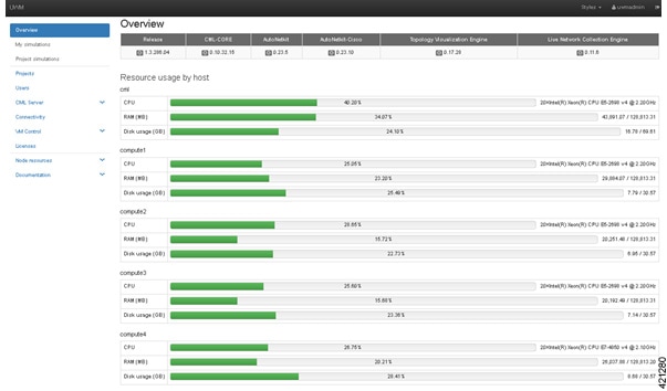 |
Cluster Troubleshooting
In situations where communication is lost between the controller and a compute node, or if a compute node becomes inoperable, you can determine the state of each compute node from the controller using the nova service-list and neutron agent-list commands.
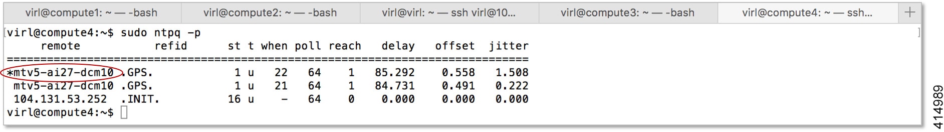
In such circumstances, correct operation may be restored by restarting the affected node.
sudo ntpq -p
Cluster Maintenance
Add Additional Compute Nodes
To add additional compute nodes to an existing Cisco Modeling Labs cluster, complete the following steps:
| Step 1 | Login to the controller at the IP address recorded during installation using username virl and password VIRL. |
| Step 2 | Edit the /etc/settings.ini file and set the configuration element for the new compute node to True. |
| Step 3 | Apply the
changes and update the controller's cluster configuration.
vinstall salt |
| Step 4 | Complete the instructions described in Compute Node Deployment for the new compute node. |
| Step 5 | Complete the instructions described in Cluster Validation to ensure that the new compute node is properly deployed. |
Cluster Configuration and Defaults
The following configuration elements defined in the /etc/settings.ini file or via the User Workspace Management interface are used to define Cisco Modeling Labs OpenStack Cluster configurations.
|
Parameter |
Default |
Description |
|
|---|---|---|---|
|
computeN_active |
False |
Specifies the absence or presence of the compute node N in the cluster. |
Set to True for each available compute node (1 through 4). |
|
computeN_nodename |
computeN |
Specifies the hostname associated with the compute node. |
This field must match the node name defined on the compute node. |
|
computeN_public_port |
eth0 |
Specifies the name of the port used to reach the Internet on the compute node. |
This field must match exactly the public port name and format specified on the compute node. |
|
computeN_using_dhcp_on_the_ public_port |
True |
Specifies the addressing method used for the public port on the compute node. |
Set to False if using Static IP addressing. |
|
computeN_static_ip |
10.10.10.10 |
The Static IP address assigned to the public port. |
Not used if DHCP is enabled. Review and modify to match deployment requirements. |
|
computeN_public_netmask |
255.255.255.0 |
The network mask assigned to the public port. |
Not used if DHCP is enabled. Review and modify to match deployment requirements. |
|
computeN_public_gateway |
10.10.10.1 |
The IP address of the default gateway assigned to the public port. |
Not used if DHCP is enabled. Review and modify to match deployment requirements. |
|
computeN_first_nameserver |
8.8.8.8 |
The IP address of the first name-server assigned to the public port. |
Not used if DHCP is enabled. Review and modify to match deployment requirements. |
|
computeN_second_nameserver |
8.8.4.4 |
The IP address of the second name-server assigned to the public port. |
Not used if DHCP is enabled. Review and modify to match deployment requirements. |
|
computeN_l2_port |
eth1 |
The name of the first layer-2 network port (Flat) on the compute node. |
This field must match exactly the name and format specified on the compute node. |
|
computeN_l2_address |
172.16.1.24N |
The IP address assigned to the first layer-2 network port (Flat) on the compute node. |
This field must match exactly the IP address specified on the compute node. N must match the node name / position in the cluster. |
|
computeN_l2_port2 |
eth2 |
The name of the second layer-2 network port (Flat1) on the compute node. |
This field must match exactly the name and format specified on the compute node. |
|
computeN_l2_address2 |
172.16.2.24N |
The IP address assigned to the second layer-2 network port (Flat1) on the compute node. |
This field must match exactly the IP address specified on the compute node. N must match the node name / position in the cluster. |
|
computeN_l3_port |
eth3 |
The name of the layer-3 network port (SNAT) on the compute node. |
This field must match exactly the name and format specified on the compute node. |
|
computeN_l3_address |
172.16.3.24N |
The IP address assigned to layer-3 network port (SNAT) on the compute node. |
This field must match exactly the IP address specified on the compute node. N must match the node name / position in the cluster. |
|
computeN_internalnet_ip |
172.16.10.24N |
The IP address assigned to internal / cluster network interface (eth4). |
This field must match exactly the IP address specified on the compute node. N must match the node name / position in the cluster. |
|
Parameter |
Compute Node 1 |
Compute Node 2 |
Compute Node 3 |
Compute Node 4 |
|---|---|---|---|---|
|
computeN_active |
False |
False |
False |
False |
|
computeN_nodename |
compute1 |
compute2 |
compute3 |
compute4 |
|
computeN_public_port |
eth0 |
eth0 |
eth0 |
eth0 |
|
computeN_using_dhcp_on_the_ public_port |
True |
True |
True |
True |
|
computeN_static_ip |
10.10.10.10 |
10.10.10.10 |
10.10.10.10 |
10.10.10.10 |
|
computeN_public_netmask |
255.255.255.0 |
255.255.255.0 |
255.255.255.0 |
255.255.255.0 |
|
computeN_public_gateway |
10.10.10.1 |
10.10.10.1 |
10.10.10.1 |
10.10.10.1 |
|
computeN_first_nameserver |
8.8.8.8 |
8.8.8.8 |
8.8.8.8 |
8.8.8.8 |
|
computeN_second_nameserver |
8.8.4.4 |
8.8.4.4 |
8.8.4.4 |
8.8.4.4 |
|
computeN_l2_port |
eth1 |
eth1 |
eth1 |
eth1 |
|
computeN_l2_address |
172.16.1.241 |
172.16.1.242 |
172.16.1.243 |
172.16.1.244 |
|
computeN_l2_port2 |
eth2 |
eth2 |
eth2 |
eth2 |
|
computeN_l2_address2 |
172.16.2.241 |
172.16.2.242 |
172.16.2.243 |
172.16.2.244 |
|
computeN_l3_port |
eth3 |
eth3 |
eth3 |
eth3 |
|
computeN_l3_address |
172.16.3.241 |
172.16.3.242 |
172.16.3.243 |
172.16.3.244 |
|
computeN_internalnet_port |
eth4 |
eth4 |
eth4 |
eth4 |
|
computeN_internalnet_ip |
172.16.10.241 |
172.16.10.242 |
172.16.10.243 |
172.16.10.244 |
 Feedback