- Cisco UCS C-Series Server Installation
- Prepare the Cisco Integrated Management Controller (CIMC) Interface
- Access the CIMC Interface
- Map the Cisco Modeling Labs ISO Disk Image
- Run the VIRL Installer
- (Optional) Prepare for an Interface-Constrained Installation
- Reconfigure Default Console Resolution
- Launch the User Workspace Management Interface
- Determine License Key Requirements
Cisco Modeling Labs
ISO Installation
Cisco UCS C-Series Server Installation
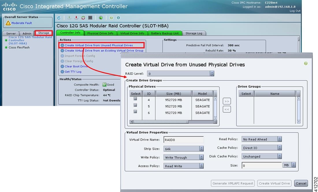
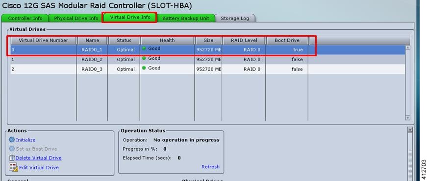
Cisco Modeling Labs has relatively modest storage requirements, with a 250GB capacity (or larger) Direct Attached Storage disk (DAS) recommended. RAID configurations are optional. When using a RAID configuration on the UCS C-Series server, the hardware based (MRAID module) version is the recommended method.
Storage Area Network (SAN) options are beyond the scope of this installation guide. SAN options are not supported for Cisco Modeling Labs bare metal deployments on Cisco UCS C-Series.
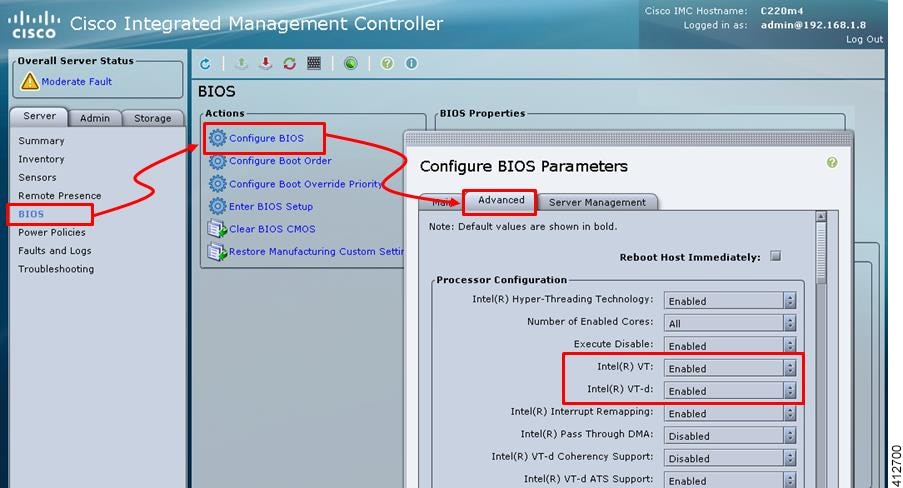
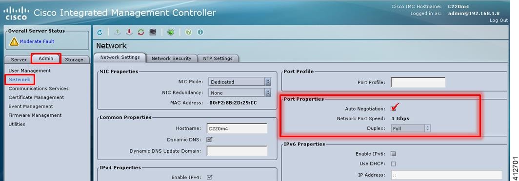
If the Cisco UCS C-Series server is being freshly deployed, there are some preliminary preparations that are necessary to prepare the hardware. These include configuring the server’s dedicated management interface (CIMC); verifying that the necessary Virtualization Technology features are enabled in the BIOS; and preparing the storage for the installation. The following steps are associated with the Cisco UCS C220 M4S platform running Version 2.06(6d) BIOS/CICM firmware. Refer to the applicable documentation if other server types or firmware levels are to be used and adjust the process accordingly.
Prepare the Cisco Integrated Management Controller (CIMC) Interface
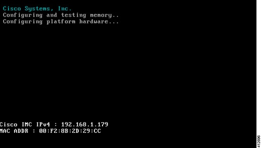
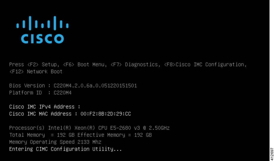
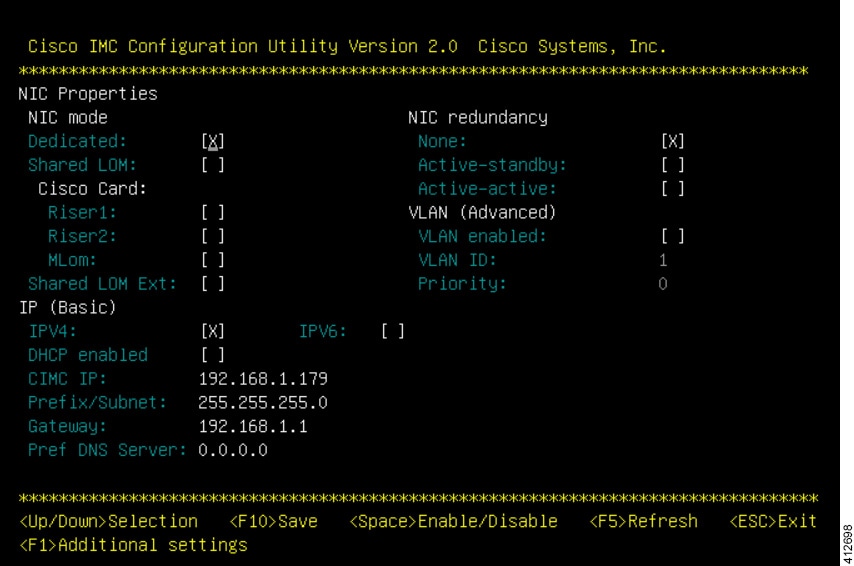
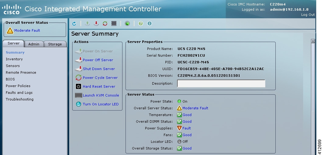
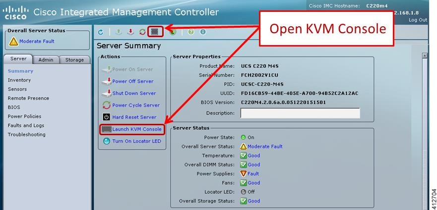
Access the CIMC Interface
With the CIMC interface configured, it is accessed to complete the machine preparation and to facilitate the software installation.
Map the Cisco Modeling Labs ISO Disk Image
To map the Cisco Modeling Labs ISO disk image, complete the following steps:
| Step 1 | With the Cisco
UCS server properly prepared for the Cisco Modeling Labs installation, the ISO
installation media must be virtually (remote) mounted to the target server. In
the CIMC interface, open a KVM Console to the server by clicking the associated
icon in the tool bar or the within the
Actions
pane.
| ||
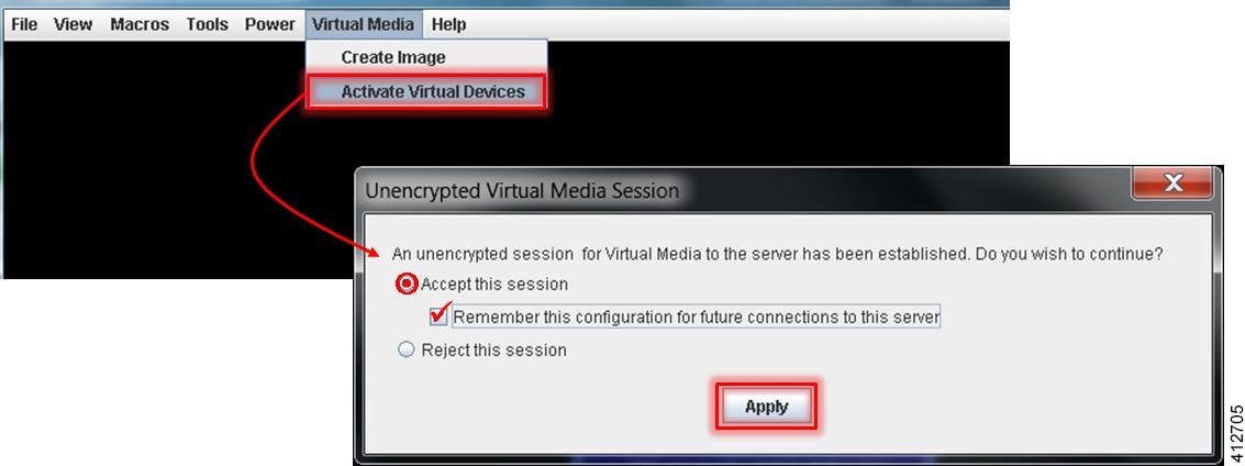
| Step 2 | In the KVM
Console window, click
Virtual
Media from the menu bar. From the drop-down, choose the
Activate
Virtual Devices. Acknowledge the
Unencrypted
Virtual Media Session warning and click
Apply, as
shown.
| ||
| Step 3 | Click
Virtual Media from the menu bar again. In the expanded
drop-down list, choose the
Map CD/DVD… option. In the resultant Virtual Media – Map
CD/DVD dialog box, browse to and select the Cisco Modeling Labs ISO file. The
ISO image file will appear in the selected Drive/Image File field; click
Map Device to continue, as shown.
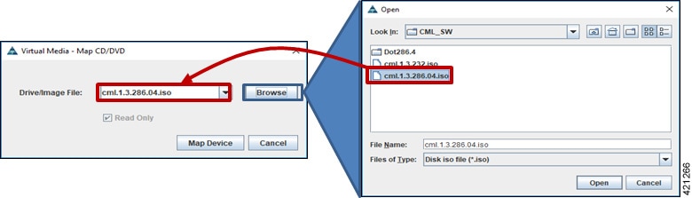
| ||
| Step 4 | In the KVM Console window, click Macros from menu banner. In the drop-down list, choose Static Macros > Ctrl-Alt-Del to trigger a server reboot. | ||
| Step 5 | During the reboot cycle, when the server setup screen is displayed, press the <F6> key. Choose the Cisco vKVM-Mapped vDVD option for the boot device. When complete, the server will boot the ISO disk image file. |
Run the VIRL Installer
Complete the following steps to install Cisco Modeling Labs.
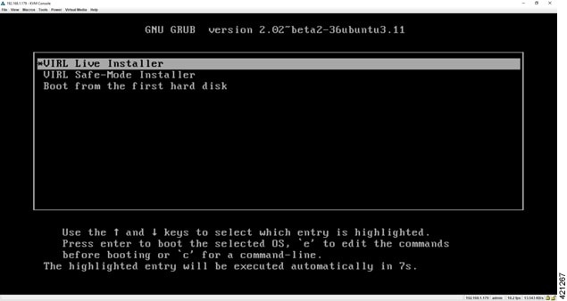
| Step 1 | Select the
VIRL Live
Installer option and press
Enter to
continue booting from the mounted ISO image file. Upon completion of the
startup cycle, the Ubuntu Desktop is presented.
 |
| Step 2 | On the desktop,
double-click
Install CML
to begin the installation.
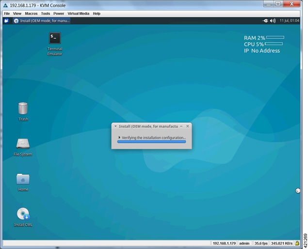 |
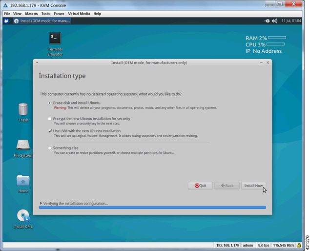
| Step 3 | After verifying
the installation configuration, the
Installation
Type page is presented. Set the Installation type to Erase disk and Install
Ubuntu. We recommend that you enable the
Use LVM with
the new Ubuntu installation option, to setup Logical Volume Management.
Click
Install Now.
|
| Step 4 | When the Disk
formatting warning is presented, click the
Continue
button to initiate the software installation process. The bar graph indicates
the software transfer process.
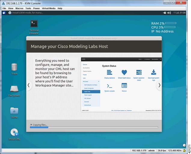 |
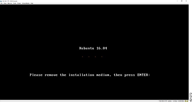
| Step 5 | When
completed, you are prompted to remove the install installation medium. Using
the virtual console menus, deselect the ISO mapping and returning to the
console session. Press
Enter to
trigger a system reboot using the freshly installed system.
 Once the system has rebooted to the local storage, return to the virtual KVM Console via the UCS CIMC interface. Logging back into the system with the virl/VIRL credentials presents the Ubuntu desktop. The upper right corner of the desktop will report the DHCP acquired IP address to the management interface. If no DHCP services are available, the report will indicate IP No Address. We recommend that the management interface be statically configured. If the system booted with an IP address, this may be changed using the User Workspace Management interface. When no DHCP services are available, a static IP address must first be configured for the management interface. |
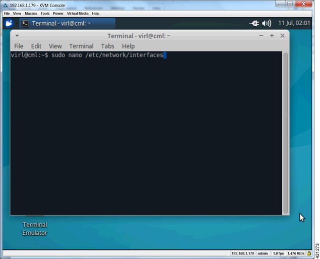
| Step 6 | From the KVM
Console, double-click the
Terminal
Emulator icon. Using a text editor, open the
/etc/network/interfaces file, as shown.
 |
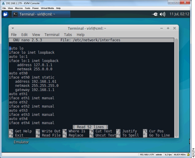
| Step 7 | Scroll to the
configuration associated with the eth0 interface. Replace the
dhcp entry
with
static.
Add the following interface configuration lines to the file immediately after
the
static
entry, as shown:
iface eth0 inet static
     address nnn.nnn.nnn.hhh
     netmask mmm.mmm.mmm.mmm
     gateway nnn.nnn.nnn.ggg
 |
| Step 8 | Enter ^X to exit the file edit mode, followed by Y to confirm saving the changes and Enter to confirm overwriting the /etc/network/interfaces file. |
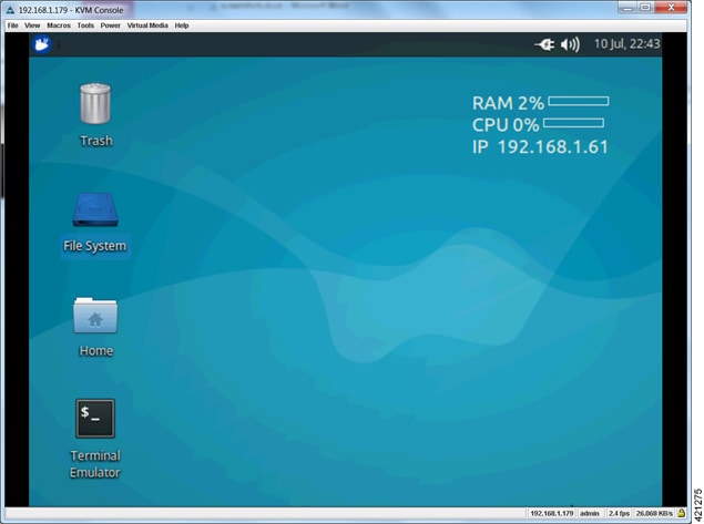
| Step 9 | To reboot the
system, enter
sudo
reboot now.
Once
the system reboot has completed, returning to the KVM virtual console shows the
IP Address to the CML's management interface, as displayed in the top
right-hand corner.
 |
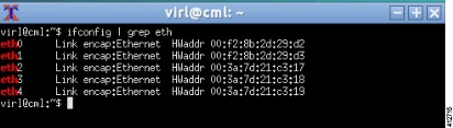
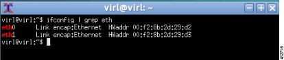
| Step 10 | Cisco Modeling
Labs installed directly onto hardware as a bare metal deployment requires (5)
network interfaces to achieve full functionality. To verify that these required
network interfaces are recognized by the system, double-click the
Terminal
Emulator icon to open an XTerminal session on the console’s desktop and
enter
ifconfig
| grep eth at the command prompt, as shown.
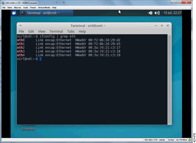 With all (5) Ethernet interfaces recognized by the system, the installation process may be completed using the User Workplace Management interface. If less than (5) Ethernet interfaces are reported, an interface-constrained deployment must first be prepared. This entails creating an alias for the missing OpenStack services IP address, and then creating a pseudo-interface (dummy) for each of the missing interfaces. |
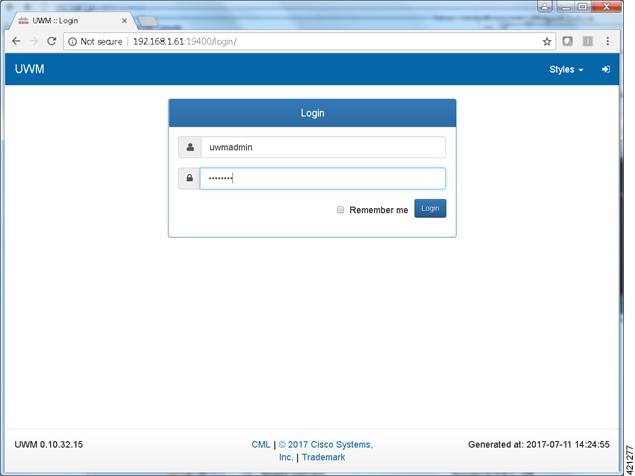
| Step 11 | Using a web
browser, connect to the IP address configured to the management interface and
login to the administrative account using the default credentials
(uwmadmin/password), as shown.
 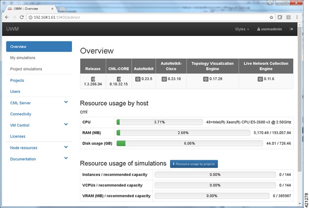 |
| Step 12 | Access the
page to set the
server’s attributes. Under the
System
tab, update the details for the primary (eth0) Ethernet port. To reconfigure
the management interface, uncheck the
Use DHCP on
primary Ethernet port toggle to disable the DHCP assignment motif and enter
the desired static assignments for the primary Ethernet port in their
respective fields.
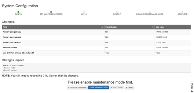
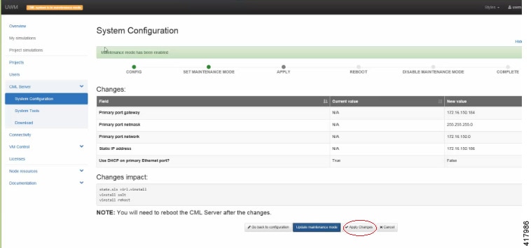
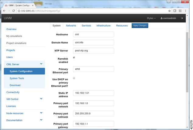 If the external communication interfaces must be adapted to integrate to local requirements, select the Networks tab, and edit the entries associated with the Flat, Flat1, and SNAT interfaces. When the adjustments have been completed, click Apply Changes. A summary list of changes is presented. You must Enable Maintenance Mode to effect the changes. A message may be sent to any current users notifying them of the system reconfiguration event. When all simulations are shut down, the system will commence its reconfiguration. For most scenarios, this process may range from 20 minutes up to about an hour to complete. When finished, the system will prompt for a reboot, after which Maintenance Mode may be disabled See the section Launch the User Workspace Management Interface for detailed instructions on how to Enable Maintenance Mode (Steps 13 to 19). |
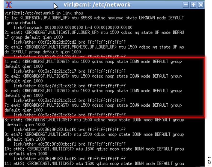
Verify that Required Interfaces are Present
The Cisco Modeling Labs bare-metal install requires 5 network interfaces, named eth0, eth1, eth2, eth3, and eth4. The presence of these interfaces should be verified at this point. Following install options 1 (live) or 2 (install), the Cisco Modeling Labs server is re-booted from the local disk. On completion of the reboot, log back into the console and open an xterm session.
-
Edit the /etc/default/grub file: sudo nano /etc/default/grub
-
Search for the follow two lines: GRUB_CMDLINE_LINUX_DEFAULT=”” GRUB_CMDLINE_LINUX=””
-
Edit the lines as follows: GRUB_CMDLINE_LINUX_DEFAULT=”biosdevname=0” GRUB_CMDLINE_LINUX=”biosdevname=0”
Figure 28. Updated File 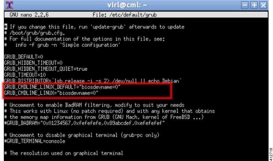
-
Save the /etc/default/grub file and exit using [Ctrl-X; Yes; Enter]
-
Complete the update using the command: sudo update-grub
-
Reboot the server to effect the changes: sudo reboot now
-
On completion of the system restart, verify that the required number of Ethernet interfaces conforming to the ethN naming format are now available on the operating system. If not, this must be diagnosed and resolved before proceeding, or the interface-constrained installation steps performed.
(Optional) Prepare for an Interface-Constrained Installation
In a bare metal deployment, if the Cisco Modeling Labs server does not have the required 5 network interfaces, the missing interfaces require pseudo-interface (dummy) references. This is done by creating an alias for the missing OpenStack services IP address, and then creating a pseudo-interface for each of the missing interfaces.
The steps described here are for a server fitted with only two network interfaces (eth0 and eth1). Three pseudo-interfaces (dummy1, dummy2, and dummy3) must be configured to compensate for the missing interfaces. Adapt the number of pseudo-interfaces in accordance with the number required for your specific deployment. This section can be skipped if the server has the requisite five network interfaces.
| Step 1 | From a console xterm session, edit the network configuration file: sudo nano /etc/network/interfaces | ||||
| Step 2 | Add a new line
in the eth0 section and enter
up ip addr
add 172.16.10.250/24 dev eth0 to create a new alias for the missing
OpenStack services address.
For example:
iface eth0 inet dhcp
        dns-nameservers 8.8.8.8 8.8.4.4
        up ip addr add 172.16.10.250/24 dev eth0
iface eth0 inet static
   address nnn.nnn.nnn.hhh
   netmask nnn.nnn.nnn.0
   gateway nnn.nnn.nnn.g
   dns-nameservers 8.8.8.8 8.8.4.4
   up ip addr add 172.16.10.250/24 dev eth0
| ||||
| Step 3 | Open the configuration file for editing: sudo nano /etc/virl.ini | ||||
| Step 4 | Change the hostname to ubuntu. This can be modified later during customization if desired. | ||||
| Step 5 | Enter Ctrl-W and
search for 'l2_port:'.
| ||||
| Step 6 | Enter Ctrl-W and search for 'l2_port2:'. In this example, since interface eth2 is missing, l2_port2: must be mapped to interface dummy1. Replace eth2 with dummy1. | ||||
| Step 7 | Enter Ctrl-W and search for 'l3_port:'. In this example, since interface eth3 is missing, l3_port: must be mapped to interface dummy2. Replace eth3 with dummy2. | ||||
| Step 8 | Enter Ctrl-W and search for 'internalnet_port:'. In this example, since interface eth4 is missing, internalnet_port: must be mapped to interface dummy3. Replace eth4 with dummy3. | ||||
| Step 9 | Enter Ctrl-W and search for 'dummy_int'. Since dummy interfaces are required dummy_int must be set to True. | ||||
| Step 10 | Enter Ctrl-X to exit nano. | ||||
| Step 11 | Enter Y and Enter to confirm saving the configuration file and exit. | ||||
| Step 12 | Enter sudo reboot now to reboot the virtual machine. | ||||
| Step 13 | Once rebooted, log in again using username virl and password VIRL. | ||||
| Step 14 | Click the xterm icon to open a terminal window. | ||||
| Step 15 | Confirm that the
OpenStack services IP address is reachable:
ping -c 4
172.16.10.250
| ||||
| Step 16 | Enter
nova
service-list to display the status of the Nova services.
Verify
that the status for each Nova service is enabled and that the state for each is
up.
| ||||
| Step 17 | Enter
neutron
agent-list to display the status of the OpenStack Neutron agents.
Verify
that the status for the Metadata, DHCP, and L3 agents is :-).
|
Reconfigure Default Console Resolution
Once the software has been installed on the server, changing the default video resolution will enable the Cisco Modeling Labs Desktop Manager GUI (Ubuntu Light Display Manager) to be accessible via the CIMC’s virtual KVM. This requires applying a shell script changing the default resolution to the lightdm configuration file.
 Note | Changing the video resolution via the Desktop Manager’s GUI menu (Preferences > Monitor Settings) is ineffective, as it does not apply to the Login page, thus preventing remote logins. |
To manually set the video to a resolution supported by the CIMC’s virtual KVM, complete the following steps:
| Step 1 | In the KVM Console window, click Macros on the menu bar. |
| Step 2 | From the drop-down menu, choose the , followed by <Enter> to switch the vConsole to a command line interface (CLI). If necessary, login with virl/VIRL. |
| Step 3 | Edit the lightdm.conf file: sudo nano /etc/lightdm/lightdm.conf |
| Step 4 | Add the following line to the file: display-setup-script=/etc/lightdm/lightdm_cml.sh |
| Step 5 | Save the file, and exit the editor: Ctrl-x; Yes; Enter |
| Step 6 | Create a lightdm_cml.sh file: sudo nano /etc/lightdm/lightdm_cml.sh |
| Step 7 | Add the following lines:
#!/bin/sh xrandr --output default --mode 1024x768 |
| Step 8 | Save the file, and exit the editor: Ctrl-x; Yes; Enter |
| Step 9 | Set the shell-script as executable by entering: sudo chmod +x /etc/lightdm/lightdm_cml.sh |
| Step 10 | Reboot the machine using the command: sudo reboot now |
Launch the User Workspace Management Interface
| Step 1 | Once the virtual
machine completes the reboot cycle, establish a browser session to the Cisco
Modeling Labs server’s management interface (either the DHCP acquired address
noted earlier, or the static address added to the /etc/network/interfaces
file.)
 | |||||||||||||||||||||||||||||||||||||||||||||||||||||||||||||||||||||||||||||||||||||||
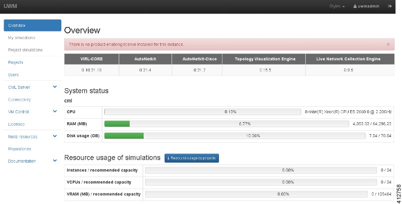
| Step 2 | Click the
User
Workspace Management interface link. Login with the default
credentials (username= uwmadmin, password=password). The
User
Workspace Management Overview page is displayed.
| |||||||||||||||||||||||||||||||||||||||||||||||||||||||||||||||||||||||||||||||||||||||
| Step 3 | From the options
on the left, expand the
CML Server
option and select
System
Configuration. Click
System to
set the system management details.
| |||||||||||||||||||||||||||||||||||||||||||||||||||||||||||||||||||||||||||||||||||||||
| Step 4 | Click
Networks
to configure the other interfaces for external communications.
| |||||||||||||||||||||||||||||||||||||||||||||||||||||||||||||||||||||||||||||||||||||||
| Step 5 | Click
Services
to configure the port numbers for services.
| |||||||||||||||||||||||||||||||||||||||||||||||||||||||||||||||||||||||||||||||||||||||
| Step 6 | Click
Infrastructure to configure the other interfaces for
external communications.
| |||||||||||||||||||||||||||||||||||||||||||||||||||||||||||||||||||||||||||||||||||||||
| Step 7 | Click
Resources
to configure the other interfaces for external communications to meet
integration requirements.
| |||||||||||||||||||||||||||||||||||||||||||||||||||||||||||||||||||||||||||||||||||||||
| Step 8 | With all
configuration options set, click
Apply
Changes. At this point, the system will ask you to please enable
maintenance mode first as shown.
 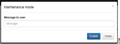 Click Enable. The system is now in maintenance mode. | |||||||||||||||||||||||||||||||||||||||||||||||||||||||||||||||||||||||||||||||||||||||
| Step 9 | Click
Apply
Changes as shown.
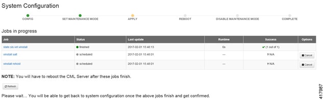 | |||||||||||||||||||||||||||||||||||||||||||||||||||||||||||||||||||||||||||||||||||||||
| Step 10 | When
completed, click
Reboot to
reboot the system.
The
Reboot System dialog box is displayed.
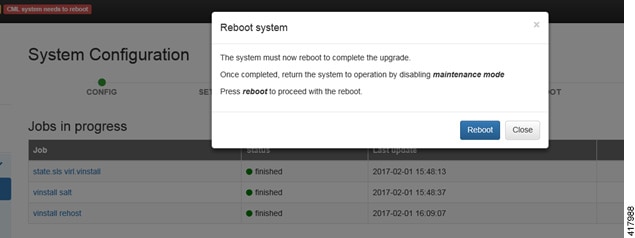 | |||||||||||||||||||||||||||||||||||||||||||||||||||||||||||||||||||||||||||||||||||||||
| Step 11 | Click
Reboot to
reboot the system.
The
System Configuration page is displayed.
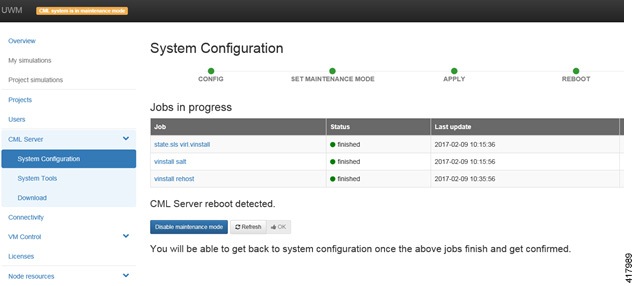 | |||||||||||||||||||||||||||||||||||||||||||||||||||||||||||||||||||||||||||||||||||||||
| Step 12 | Click
Disable
Maintenance Mode.
A
Maintenance Mode dialog box is displayed.
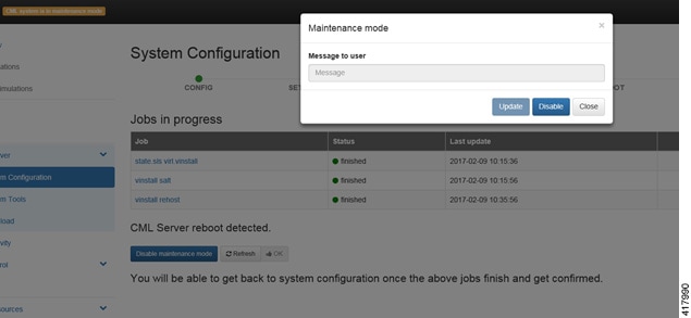 | |||||||||||||||||||||||||||||||||||||||||||||||||||||||||||||||||||||||||||||||||||||||
| Step 13 | Click
Disable.
The system is no longer in maintenance mode.
Your
configuration is complete.
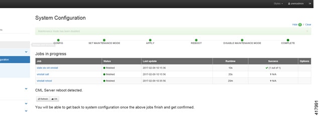 | |||||||||||||||||||||||||||||||||||||||||||||||||||||||||||||||||||||||||||||||||||||||
| Step 14 | Click OK on the System Configuration page to return to the System Configuration Controls page. |
Determine License Key Requirements
Returning to the
User Workplace Management interface shows the server’s current licensing
status; the red banner indicates that there is no product licensing in place.
To license the Cisco Modeling Labs server, complete the following steps:
| Step 1 | In the left
pane, click
Licenses.
The
Licenses page is displayed.
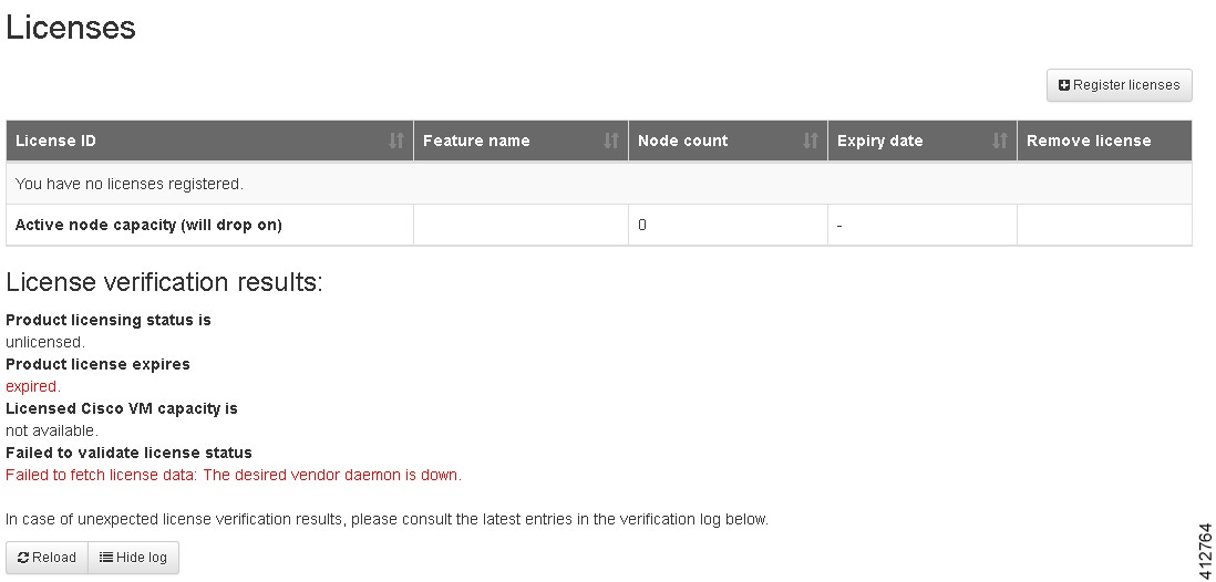 | ||||||||
| Step 2 | In the Licenses page, click Register Licenses. | ||||||||
| Step 3 | Record the
Host Name and
Mac Address for
license key registration.
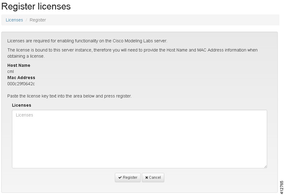 Use this information when completing the Register Claim Certificates instructions in the eDelivery Order Notification email to request your license key for use with the Cisco Modeling Labs server.
You will receive your license key as an attachment via an email. | ||||||||
| Step 4 | Open the attachment in a text editor and copy all of the contents. | ||||||||
| Step 5 | Return to the
Register
Licenses
page and paste the details into the
Licenses
text area.
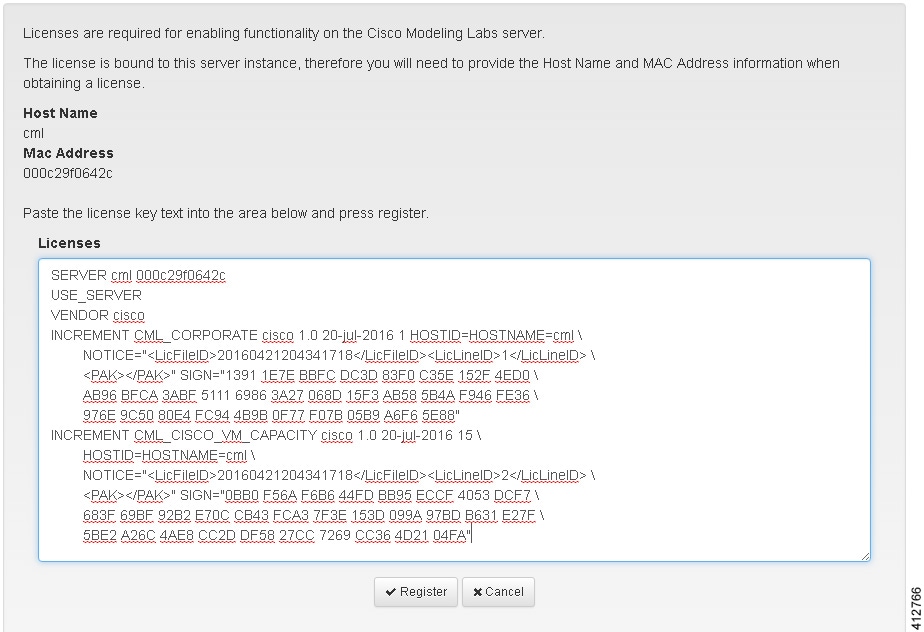 | ||||||||
| Step 6 | Click
Register to
register the license key.
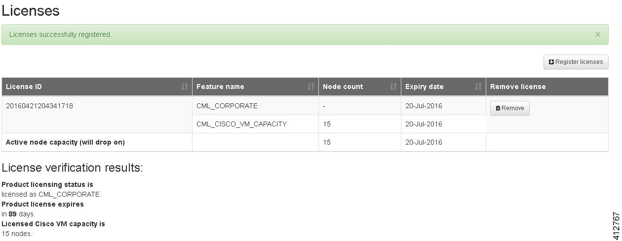 | ||||||||
| Step 7 | Repeat Steps 4 – 6 for each license file received from the registration process. Verify that the Licenses page correctly reports the applied node count and expiration dates. | ||||||||
| Step 8 | Click Log Out to exit the User Workspace Management interface. |
 Feedback