Cisco Modeling Labs OVA Installation

Configure Security and Network Settings


Note


When configuring the Cisco Unified Computing System (Cisco UCS) hardware, you must enable Intel Virtualization Technology (Intel VT) in the BIOS for Cisco Modeling Labs to operate correctly.
Before You Begin
  • Ensure that you have met the requirements as specified in the section Cisco Modeling Labs Server Requirements.
  • Ensure that you have administrator access to the VMware ESXi server in which you plan to deploy the Cisco Modeling Labs open virtual appliance (OVA) in order to enable nested virtualization.

    Step 1   Log in as administrator to the remote VMware ESXi server using the VMware vSphere client.
    Step 2   Click the Configuration tab.
    Step 3   Choose Software > Security Profile.
    Step 4   Click Properties to edit the properties associated with security services.
    Step 5   The Services Properties dialog box is displayed. Enable SSH access, ESXi Shell, and Direct Console UIas follows:
    1. Click Options.
    2. Click the Start and stop with host radio button.
    3. Click Start.
    4. Click OK.
      Figure 1. Services Properties


    Step 6   Click OK.
    Step 7   To add the two additional port groups FLAT or SNAT or both, and configure network settings, choose Hardware > Networking.
    Step 8   Click Add Networking.
    Step 9   In the Add Network wizard, make sure that the connection type is set to Virtual Machine.
    Step 10   Click Next.
    Figure 2. Connection Type


    Step 11   Click Network Access.
    Step 12   In the right pane, click Use vSwitch0.
    Step 13   Click Next.
    Figure 3. Virtual Machine Network Access


    Step 14   Choose Connection Settings > Port Group Properties.
    Step 15   In the Network Label field, enter FLAT and assign a value, for example, 10, to the VLAN ID.
    Step 16   Click Next. The new port group is displayed.
    Figure 4. FLAT Port Group Assigned


    Step 17   Repeat Step 6 to Step 11 to add the port group SNAT and assign a value, for example, 20, to the VLAN ID. The VLAN ID values are arbitrary; assign adequate values for your deployment.

    The new port group is displayed in the Preview pane.

    Figure 5. SNAT Port Group Assigned


    Step 18   Configure the port groups to allow promiscuous mode as follows:
    1. Under the Configuration tab, choose Hardware > Networking and click Properties of the port group for which you want to enable promiscuous mode.
    2. Select the applicable port group and click Edit.
    3. Click the Security tab.
    4. From the Promiscuous Mode drop-down list, choose Accept.
    Step 19   Click Finish. Both FLAT and SNAT port groups are assigned as shown.
    Figure 6. FLAT and SNAT Port Groups Assigned


    What to Do Next

    Deploy the Cisco Modeling Labs OVA.

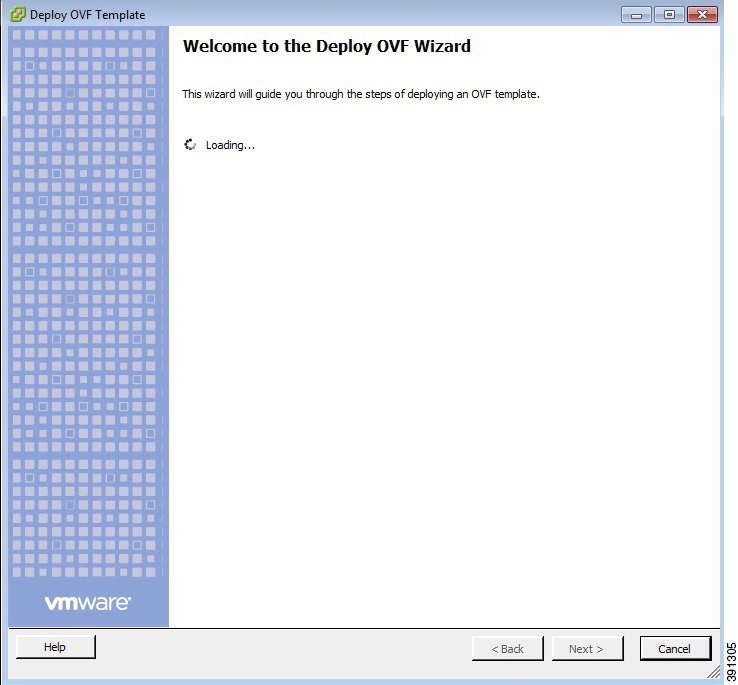
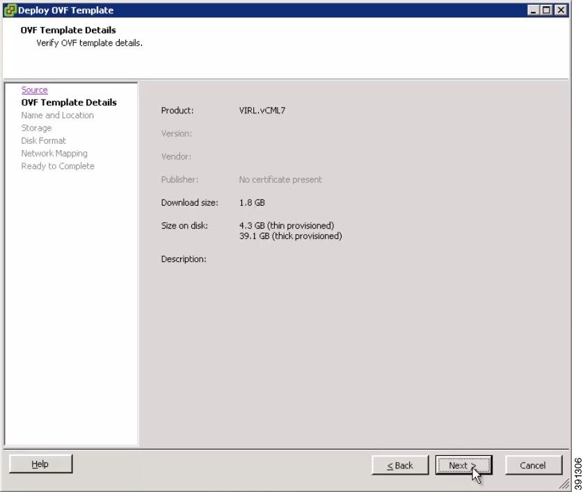
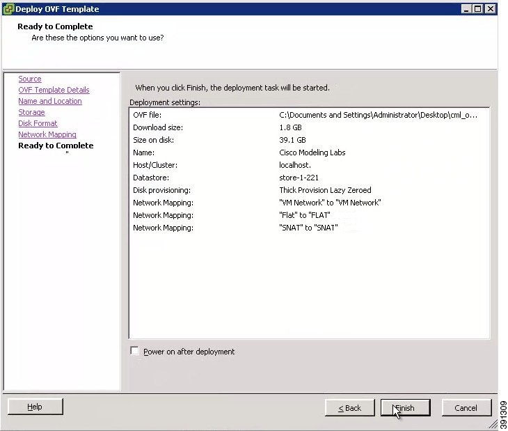
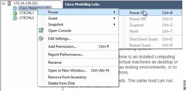
    Deploy the Cisco Modeling Labs Open Virtual Appliance

    Before You Begin
    • Ensure that you have configured the necessary security and network settings.

      Step 1   To install the OVA, log in to the VMware ESXi server.
      Step 2   From the vSphere client menu, choose File > Deploy OVF Template.
      Figure 7. Deploying OVA


      Step 3   Click Next.
      Step 4   In the Source window, click Browse to navigate to the OVA package.
      Step 5   In the dialog box displayed, click Open.
      Step 6   Click Next.
      Figure 8. OVF Template Details


      Information about the OVA you are about to deploy is displayed.
      Step 7   In the Name and Location window, provide a name for the virtual machine, for example, Cisco Modeling Labs and click Next.
      Figure 9. Name and Location Details


      Step 8   In the Storage window, click the target data storage (Datastore) and click Next.
      Figure 10. Target Datastore Details


      Step 9   In the Disk Format window, choose the target data storage (Datastore) disk format, and click Next.
      Figure 11. Disk Format Details


      Step 10   In the Network Mapping window, map the virtual networks FLAT and SNAT defined in the OVA, with those present in the host, and click Next.
      Figure 12. Network Mapping Details


      Step 11   In the Ready to Complete window, ensure that the Power on after deployment check box remains unchecked to allow the virtual machine settings to be updated before it is powered on.
      Step 12   Click Finish to start the OVA deployment.
      Figure 13. Final Summary Page


      Step 13   After the OVA is deployed, navigate to the new virtual machine, right-click and select Upgrade Virtual Hardware if this is applicable to your VMware ESXi version.
      Figure 14. Upgrade Virtual Hardware Option

      Note    To check if the upgrade is completed successfully, check under Recent Tasks.
      Step 14   In the Confirm Virtual Machine Upgrade dialog box, click Yes.
      Note    The option to upgrade the virtual hardware will not be displayed if the virtual machine is powered on, or if it already has the latest supported virtual hardware version.
      Step 15   Use a terminal application, such as PuTTY, to connect to the VMware ESXi server using SSH.
      • Use the same IP address as your vSphere client.

      • Log in to the deployment using an account with administrator access.

      Figure 15. Log In to the Deployed OVA


      Step 16   After logging into the VMware ESXi server, complete the following steps:
      1. Change the directory to /vmfs/volumes/ directory.
      2. Select the datastore, as specified in Step 8.
        Figure 16. Accessing the Datastore


      3. Select the name of the server as specified in Step 7.
      4. For VMware ESXi 5.0, add the following command to the /etc/vmware/config file:
        vhv.allow = "TRUE"
      5. Edit the .vmx file associated with the new virtual machine using a text editor for example, vi Editor. Add the following commands to enable support for nested hypervisors by the virtual machine: For VMware ESXi 5.0:
        cpuid.1.ecx="----:----:----:----:----:----:--h-:----" 
        cpuid.80000001.ecx.amd="----:----:----:----:----:----:----:-h--" 
        cpuid.8000000a.eax.amd="hhhh:hhhh:hhhh:hhhh:hhhh:hhhh:hhhh:hhhh" 
        cpuid.8000000a.ebx.amd="hhhh:hhhh:hhhh:hhhh:hhhh:hhhh:hhhh:hhhh" 
        cpuid.8000000a.edx.amd="hhhh:hhhh:hhhh:hhhh:hhhh:hhhh:hhhh:hhhh" 
        monitor.virtual_mmu = "hardware" 
        monitor.virtual_exec = "hardware" 
        vcpu.hotadd = "FALSE"
        For VMware ESXi 5.1 and VMware ESXi 5.5:
        vhv.enable = "TRUE"
        virtualHW.version = "9"
        Note    The vhv.allow command applies to ESXi Version 5.0 only and the vhv.enable command applies to ESXi Version 5.1 and later.
        Note    Choose the command that is appropriate to your VMware ESXi server version and add it to your .vmx file along with the other commands.
      Step 17   Save the file and exit.
      Step 18   To power on your Cisco Modeling Labs server for the first time, right-click Cisco Modeling Labs and choose Power > Power On in the vSphere client.
      Figure 17. Powering On the Cisco Modeling Labs Server


      What to Do Next

      Start the Cisco Modeling Labs Server.