Design Your Network

Design A New Network Infrastructure

The Design area is where you create the structure and framework of your network including the physical topology, network settings, and device type profiles that you can apply to devices throughout your network. You use the Design workflow if you do not already have an existing infrastructure. If you have an existing infrastructure, use the Discovery feature.

You perform these tasks in the Design area:
Procedure
    Step 1   Create your network hierarchy. See Create Sites in the Network Hierarchy.
    Step 2   Define global network settings. See About Global Network Settings.
    Step 3   Define network profiles.

    About Network Hierarchy

    You can create a network hierarchy that represents your network's geographical locations. Your network hierarchy can contain sites, which contains buildings and areas. You create site and building IDs so that later, you can easily identify where to apply design settings or configurations.

    • Areas don't have a physical address (i.e., United States). You can think of areas as the largest element. Areas can contain buildings and subareas. For example, an area called United States can contain a subarea called California. And the subarea California can contain a subarea called San Jose. By creating areas, you can apply common settings across a large area.

    • Buildings have physical address and contain floors and floor plans. When you create a building, you must specify a physical address and latitude and longitude coordinates. Buildings cannot contain areas. By creating buildings, you can apply settings to a specific area.

    You can

    Create Sites in the Network Hierarchy

    DNA Center allows you to easily define physical sites and then specify common resources for those sites. The Design application uses a hierarchical format for intuitive use, while eliminating the need to redefine the same resource in multiple places when provisioning devices. By default, there is one site called Global. You can add additional sites, buildings, and areas to your network hierarchy. You must create at least one site before you can use the Provision features.

    Procedure
      Step 1   Choose Design. A world map is displayed.
      Step 2   Click Add Site.
      Step 3   Choose whether to create an area or a building. You can also upload an exsiting hiearchy.
      Step 4   Enter a name for the site or building and select a parent node. By default, Global is the Parent Node.
      Step 5   When you add a building, you must enter an address in the Address field. As you enter the address, the Design App narrows down the known addresses to the one you enter. When you see the correct address appear in the window, select it. When you select a known address, the longitude and latitude coordinates fields are automatically populated.
      Step 6   Click Add. The area or building you created is added under the Global site.
      Step 7   To add another area or building, in the hierarchy frame, click the gear icon next to an existing area or building that you want to be the parent node.

      Add Floors to Buildings

      After you add a building, you can create floors and upload a floor map.
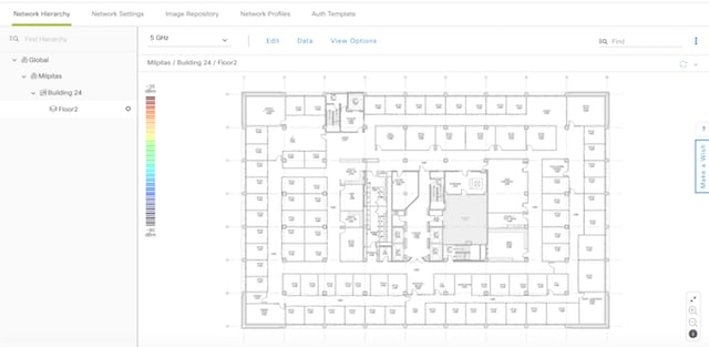
      Procedure
        Step 1   Choose Design > Network Hierarchy.
        Step 2   Expand the Global site and the previously created area to see all the previously created buildings.
        Step 3   Click the gear icon next to the building for which you want to add a floor, then click Add Floor.
        Step 4   Complete the required fields. The Floor Name field has a 21 character limit. The floor name must start with a letter or a hyphen (-) and the string following the first character can include one or more of the following:
        • Upper and/or lower case letters

        • Numbers

        • Underscores (_)

        • Hypens (-)

        • Periods (.)

        Step 5   Click Add.
        Step 6   You can then drag a floor plan on to the map or upload a file. DNA Center supports the following file types: .jpg, .gif, .png, .dxf, and .dwg.

        After you upload a floor plan, you should see the map displayed in the window.

        Figure 1. Example Floor Plan


        Edit Floors

        After you add a floor, you can edit the floor map so that it contains the obstacles, areas, and APs contained on the floor.

        Procedure
          Step 1   Choose Design > Network Hierarchy.
          Step 2   Expand the network hierarchy to find the floor you want to edit, or enter the floor name in the Search Hierarchy field.
          Step 3   Click on the name of the floor you want to edit. The floor map appears.

          Place Cisco APs on a Floor

          Procedure
            Step 1   Choose Design > Network Hierarchy.
            Step 2   Expand the network hierarchy to find the floor you want to edit, or enter the floor name in the Search Hierarchy field.

            The floor map is displayed in the right pane.

            Step 3   Click Manage Floor APs.

            The Add APs dialog box, which lists the available APs along with the AP Name and AP Mode details, appears. The table also lists APs that are not assigned to any floors.

            Step 4   Click Add adjacent to the AP that you want to place on the floor map. The APs that are added appear on the right side of the floor map.
            Step 5   To position the APs correctly on the floor map, click and drag each AP to the appropriate location on the floor map, or click an AP point icon on the floor map to open the Properties window and set the horizontal and vertical position for that AP.
            Step 6   Click Save.
            Step 7   (Optional) Hover your cursor over an AP icon on the floor map to view the corresponding details.

            Upload Existing Site Hierarchy

            You can upload a CSV file that contains an existing network hierarchy. For example, you can upload a CSV file with location information that you exported from Cisco Prime Infrastructure. See Export Device Configurations for information about how to export devices.

            Procedure
              Step 1   Choose Design > Network Hierarchy, then click Create Site.
              Step 2   At the bottom of the form, click Upload CSV. If you don't have an existing CSV file, click Download Template to download a CSV file you can edit and then upload.
              Step 3   Navigate to where your CSV file is located, then click Open. The site hierarchy is uploaded.

              Search the Network Hierarchy

              You can search the network hierarchy to quickly find a site, building, or area. This is particularly helpful after you've added a large number of sites, areas, or buildings.

              Procedure
                Step 1   To search the tree hierarchy, place your cursor in the Search Hierarchy window and enter the test on which you want to search. The tree is filtered on the information you enter in the search window.
                Step 2   To search the map view, place your cursor in the Search Buildings window and enter the name of the building for which you want the map view to display.

                Configure Global Wireless Settings

                Global wireless network settings include settings for Service Set Identifier (SSID), wireless interfaces, and wireless radio frequency.


                Note


                Creating wireless interfaces and wireless radio frequency is applicable only for nonfabric deployments.


                The following sections provide information about how to define various global wireless network settings:

                Create SSIDs for an Enterprise Wireless Network

                This workflow shows how to:

                1. Create SSIDs.

                2. Create wireless profiles.

                3. Associate SSIDs to wireless profiles.

                Procedure
                  Step 1   Choose Design > Network Settings > Wireless.
                  Step 2   Under Enterprise Wireless, click + Add to create a new SSID for the enterprise network.

                  In the Create an Enterprise Wireless Network window, configure the following parameters:

                  Step 3   Enter an SSID name in the Wireless Network Name (SSID) field.
                  Step 4   Select the Type of Enterprise Network: Voice and Data or Data Only. This selection defines the quality of service (QoS).
                  Step 5   Check the Fast Lane check box to enable fastlane capability on this network.
                  Step 6   Under Level of Security area, select the encryption and authentication type for this network. The security options are:
                  • WPA2 Enterprise—Provides a higher level of security using Extensible Authentication Protocol (EAP) (802.1x) to authenticate and authorize network users with a remote RADIUS server. If you select WPA Enterprise, check the MAC Filtering check box to enable MAC-based access control on an SSID.

                  • WPA2 Personal—Provides good security using a passphrase or a preshared key (PSK). Allows anyone with the passkey to access the wireless network. If you select WPA2 Personal, enter the passphrase in the Passphrase text box.

                  • Open—Provides no security. Allows any device to access the wireless network without any authentication.

                  Step 7   Click Next. The Wireless Profiles window is displayed. You can associate this SSID with the corresponding wireless profile. See Step Step 4 to associate an SSID with the existing wireless profile, Step Step 3 to create a new wireless profile.
                  Step 8   In the Wireless Profiles window, click +Add to create a new wireless profile.

                  The Create a Wireless Profile window appears. Configure the following:

                  Step 9   Enter the profile name in the Wireless Profile Name text box.
                  Step 10   Specify whether the SSID is Fabric or Non-Fabric by selecting Yes or No.
                  • For Non-Fabric SSID, select the authentication method: Central or Local to VLAN. For central authentication, from the Interface Name drop-down list, select the interface name. For local authentication, Cisco WLC redirects the HTTP traffic to an internal or external server where the user is prompted to authenticate. In case of a guest user, an external server such as Cisco ISE is required for registering and self-provisioning. From the Select ISE Authentication drop-down list, select a Cisco ISE authentication server and enter the redirect URL in the Redirect URL text box. The client is redirected to the specified Cisco ISE redirect URL.

                  Step 11   To assign this profile to any site, enter the site name in the Site Selector text box.
                  Step 12   Click Finish. The created profile appears in the Wireless Profiles page.
                  Step 13   To associate the SSID to wireless profile, do the following:
                  • On the Wireless Profile page, check the Profile Name check box(es) to associate the SSID you created in Step 2.

                  • Click Finish.


                  What to Do Next

                  1. Perform discovery of devices. You can discover devices using CDP or using an IP address range. See Discover Your Network Using CDP and Discover Your Network Using an IP Address Range.

                  2. Configure policies for your network. See Configure Policies.

                  3. Add Cisco WLC to a site. See Add Devices to Sites.

                  4. Provisioning Cisco WLCs and Cisco APs. See Provision a Cisco WLC and Provision a Cisco AP - Day 1 AP Provisioning.

                  5. Add Cisco WLC to a fabric domain. See Add Devices to a Fabric.

                  6. Configure settings for the various kinds of devices ("hosts") that can access the fabric domain, see Configure Host Onboarding.

                  Create SSIDs for a Guest Wireless Network

                  This workflow shows how to:

                  1. Create SSIDs.

                  2. Create wireless profiles.

                  3. Associate SSIDs to wireless profiles.

                  4. Guest portal customization.

                  Procedure
                    Step 1   Choose Design > Network Settings > Wireless.
                    Step 2   Under Guest Wireless, click +Add to create new SSIDs.

                    In the Create a Guest Wireless Network window, configure the following parameters:

                    Step 3   Enter an SSID name in the Wireless Network Name (SSID) text box.
                    Step 4   Under Level of Security, select the encryption and authentication type for this guest network. The security options are: Web AUTH and Open.
                    • WEB AUTH—Provides higher level of layer 3 security.

                      Note   

                      The WEB AUTH option is disabled if you do not have Cisco ISE configured on the DNA Center server. Cisco ISE acts as a RADIUS server for web authentication.

                    • Open—Provides no security. Allows devices to connect to the wireless network without any authentication.

                    Step 5   Select the authentication server: ISE Authentication or External Authentication. For ISE Authentication, configure the following:
                    • Select the type of portal you want to create from the WHAT KIND OF PORTAL ARE YOU CREATING TODAY ? drop-down list:

                      • Self Registered—The guests are redirected to the Self-Registered Guest portal to register by providing information to automatically create an account.

                      • HotSpot —The guests can access the network without credentials.

                    Step 6   Select where you want to redirect the guests after successful authentication from the WHERE WILL YOUR GUESTS REDIRECT AFTER SUCCESSFUL AUTHENTICATION ? drop-down list:
                    • Success Page—The guests are redirected to an authentication success page.

                    • Original URL—The guests are redirected to the URL they had originally requested.

                    • Custom URL—The guests are redirected to the custom URL that is specified here. You need to enter a redirect URL in the Redirect URL text box.

                    Step 7   Click Next. The Wireless Profiles window is displayed. You can associate this SSID with the correponsing wireless profile. See Step Step 4 to associate an SSID with the existing wireless profile, and Step Step 3 to create a new wireless profile.
                    Step 8   In the Wireless Profiles window, click +Add to create a new wireless profile.

                    The Create a Wireless Profile window appears.

                    • Enter the profile name In the Wireless Profile Name text box.

                    • Specify whether the SSID is Fabric or Non-Fabric by selecting Yes or No.

                    • To assign this profile to any site, enter the site name in the Site Selector field.

                    • Click Save. The created profile appears in the Wireless Profiles page.

                    Step 9   To associate the SSID to wireless profile, do the following:
                    • On the Wireless Profiles page, check the Profile Name check box(es) to associate the SSID.

                    • Click Next.

                      The Portal Customization page appears. You can assign the SSID to a guest portal.

                    Step 10   On the Portal Customization page, click + Add to create the guest portal. The Portal Builder page appears. See Portal Customization to create custom portals. The created portal appears in the Portal Customization page.
                    • Under Portals, select the radio button next to Portal Name to assign the SSID to guest portal.

                    Step 11   Click Finish.

                    What to Do Next

                    1. Perform discovery of devices. You can discover devices using CDP or using an IP address range. See Discover Your Network Using CDP and Discover Your Network Using an IP Address Range.

                    2. Configure policies for your network. See Configure Policies.

                    3. Add Cisco WLC to a site. See Add Devices to Sites.

                    4. Provisioning Cisco WLCs and Cisco APs. See Provision a Cisco WLC and Provision a Cisco AP - Day 1 AP Provisioning.

                    5. Add Cisco WLC to a fabric domain. See Add Devices to a Fabric.

                    6. Configure settings for the various kinds of devices ("hosts") that can access the fabric domain, see Configure Host Onboarding.

                    Create a Guest Portal Page

                    You can create the following guest portal pages:

                    • Login Page

                    • Registration Page

                    • Registration Success

                    • Success Page

                    Procedure
                      Step 1   Navigate to the portal page you are creating.
                      Step 2   Enter the portal name in the Portal Name text box.
                      Step 3   Expand Page Content in the left menu to include various variables while creating portal pages.
                      • List of variables for Login page:

                        • Access Code

                        • Header Text

                        • AUP

                        • Text Fields

                      • List variables for Registration page:

                        • First Name

                        • Last Name

                        • Phone Number

                        • Company

                        • Sms Provider

                        • Person being visited

                        • Reason for a visit

                        • Header text

                        • User Name

                        • Email Address

                        • AUP

                      • List of variables for Registration page:

                        • Account Created

                        • Header texts

                      • Variables for Success page:

                        • Text fields

                      Step 4   Drag and drop variables in to the portal template page and edit them.
                      Step 5   To customize the default color scheme in the portal, expand Color in the left menu and change the color of these page elements:.
                      • Body text Border

                      • Link text Page

                      • Background

                      • Border Color

                      • Header Background

                      Step 6   To customize the font, expand Font in the left menu and change the following:
                      • Typeface

                      • Header

                      • Title text

                      • Body text

                      • Form label

                      Step 7   Click Save to save the portal.

                      Create a Wireless Interface

                      Creating wireless interfaces is applicable for nonfabric deployment.

                      Procedure
                        Step 1   Choose Design > Network Settings > Wireless.
                        Step 2   Under Wireless Interfaces, click +Add.

                        The New Interfaces window appears.

                        • In the Interfaces Name text box, enter the dynamic interface name.

                        • (Optional) In the VLAN ID text box, enter the VLAN ID for the interface. The valid range is 0 to 4094.

                        • Click Ok. The created interface appears under Wireless Interfaces.


                        Create a Wireless Radio Frequency Profile

                        Creating wireless radio frequency profile is applicable for Non-Fabric deployment.

                        Procedure
                          Step 1   Choose Design > Network Settings > Wireless.
                          Step 2   Under Wireless Radio Frequency Profile, click +Add RF.

                          The Wireless RAdio Frequency window appears.

                          Step 3   In the Profile Name text box, enter the Radio Frequency (RF) profile name.
                          Step 4   Select at least one radio type: 2.4 GHz or 5 GHz.
                          Step 5   Configure the following for 2.4 GHz radio type:
                          • Check the DCA Channel check box(es) to select channels to dynamically manage channel assignment for an RF group. The available channels are: 1, 2, 3, 4, 5, 6, 7, 8, 9, 10, 11, 12, 13, and 14.

                          • Check the Data Rates check box (es) to specify the rates at which data can be transmitted between the access point and the client. The available data rates are: 1, 2, 5, 6, 9, 11, 12, 18, 24, 36, 48, and 44.
                          Step 6   Configure the following for 5 GHz radio type:
                          • Choose one of the channel bandwidth options from the Channel Width drop-down list: Best, 20 MHz, 40 MHz, 80 MHz, or 160 MHz.

                          • Set the DCA Channel to manage the channel assignments:

                            • UNNI-1 36-48—The channels available for UNII-1 band are: 36, 40, 44, and 48. Check the UNII-1 36-48 check box to include all channels or check the check box (es) of the channels to select them individually.

                            • UNII-2 52-144—The channels available for UNII-2 band are: 52, 56, 60, 64, 100, 104, 108, 112, 116, 120, 124, 128, 132, 136, 140, and 144. Check the UNII-2 52-144 check box to include all channels or check the check box (es) of the channels to select them individually.

                            • UNII-3 149-165—The channels available for UNII-3 band are: 149, 153, 157, 161, and 165. Check the UNII-3 149-165 check box to include all channels or check the check box (es) of the channels to select them individually.

                          • Check the Data Rates check box(es) to specify the rates. the available data rates are: 6, 9, 12, 18, 24, 36, 48, and 54.

                          Step 7   Click OK.