Install Fleet Upgrade

This document covers the following topics:

Plan your installation

This document provides introductory information on how to plan your installation of Cisco Crosswork Workflow Manager Solutions Fleet Upgrade and its supporting software.

Installation workflow

To install Fleet Upgrade, you must install or configure the following components, in this order:

  1. Crosswork Server: Install a virtual machine (VM) server to host the primary Cisco Crosswork platform infrastructure.

  2. NSO Server: Install a second, separate, native Linux or Linux VM server hosting Cisco Network Services Orchestrator (NSO). NSO performs the direct manipulation of your network devices.

  3. Workflow Manager and Fleet Upgrade CAPPs: Once the primary Crosswork platform server is installed and configured, you can install on it the Cisco Crosswork Workflow Manager (CWM) and CWM Solutions (CWM-S) CAPPs1. These CAPPs enable CWM and the CWM-S Fleet Upgrade functions.

  4. Crosswork Credential Profiles and NSO Provider: Configure on Crosswork a pair of credential profiles and an NSO Provider that will allow secure communications between Crosswork, your devices, and NSO. You will create these on the Crosswork server, using the Crosswork administrative user interface.

  5. NSO Packages: Install on NSO a set of update packages that allow NSO and Crosswork to share data.

Choose your Crosswork Server VM deployment method

You must install the Crosswork server on a single VM. You can do this using VM hypervisor software from either VMware or KVM. If you choose VMware, you also have the option of creating the VM using either Docker or the native VMware vCenter vSphere installation tools. This gives you a choice of three possible deployment methods.

Before making your VM deployment decision, you will want to review the hardware, software, networking, port and other requirements described in Meet installation requirements. You will also want to review the information you will need to provide for each deployment option, as detailed in Gather installation parameter values. Finally, you will also want to consider whether VMware or KVM best fits your needs.

Meet installation requirements

This document explains the requirements you must meet in order to install Cisco Crosswork Workflow Manager Solutions successfully.

Hardware requirements

Server hardware resources for the virtual machines are as follows:

  1. Crosswork Server Requirements: The VM hardware requirements for VMware and KVM deployments are similar:

    1. VMware: You can install the VMware hypervisor using either vCenter vSphere or Docker tools, on a hardware server other than the one on which NSO is installed. Cisco recommends a server with a minimum of 24 virtual CPUs, 128 GB RAM, and 1 Tb disk storage. Due to their high performance, Cisco recommends solid state drives (SSDs) over hard disk drives (HDDs). If you are using HDDs, their minimum speed should be over 15,000 RPM. The VM data store(s) must have disk-access latency less than 10 ms or greater than 5,000 IOPS.

    2. KVM: The server must be running an Intel Xeon CPU E5-2699 v4 at 2.20GHz or better, with a minimum of 24 virtual CPUs, 128 GB RAM, and 1 Tb disk storage, with 2 x 10 Gbps NICs. Install Red Hat Enterprise Linux (RHEL) 9.4 or later. Allocate a 20% buffer for CPU and memory, and a 30% buffer for storage to ensure smooth performance and prevent issues.

  2. NSO Server Requirements: You can use native Linux or any container-based implementation of your choice. The Cisco NSO installed version must be 6.4.1.1 or later. It must be a system install, not a local install (see the links to understand the difference and for help ensuring you have the correct installation type). For flexibility reasons, the NSO server must be separate from the Crosswork platform server. Cisco recommends a server with a minimum of 16 virtual CPUs, 256 GB RAM, and 1Tb disk storage. Also, customers who do not already have a separate NSO deployment meeting these requirements may wish to install NSO after deploying Crosswork on VMware or KVM. It takes about an hour for the Crosswork platform infrastructure to come up on a VM, and this delay provides plenty of time to install NSO. In addition, before installing the CWM and CWM Solution CAPPs, you must install the pre-requisite NSO packages and perform the additional configurations detailed in NSO package pre-installation tasks.

VMware installation requirements

In addition to meeting the hardware requirements discussed above, Crosswork server installations performed using VMware must meet the following installation requirements (this includes both vSphere and Docker):

  • Fleet Upgrade supports the following VMware hypervisor and vCenter versions:

    • VMware vCenter Server 8.0 (U2c or later) and ESXi 8.0 (U2b or later)

    • VMware vCenter Server 7.0 (U3p or later) and ESXi 7.0 (U3p or later)

  • Cisco Crosswork VM (Hybrid node) must be hosted on hardware with Hyper Threading disabled.

  • Ensure that profile-driven storage is enabled by the vCenter admin user. Query permissions for the vCenter user at the root level (for all resources) of the vCenter.

  • Cisco recommends that you enable vCenter storage control.

  • The networks required for the Crosswork Management and Data networks need to be built and configured in the data centers, and must allow low-latency L2 communication (latency with RTT <= 10 ms).

  • Ensure the user account you use for accessing vCenter has the following privileges:

    • VM (Provisioning): Clone VM on the VM you are cloning.

    • VM (Provisioning): Customize on the VM or VM folder if you are customizing the guest operating system.

    • VM (Inventory): Create from the existing VM on the data center or VM folder.

    • VM (Configuration): Add a new disk on the data center or VM folder.

    • Resource: Assign a VM to a resource pool on the destination host or resource pool.

    • Datastore: Allocate space on the destination datastore or datastore folder.

    • Network: Assign the network to which the VM will be assigned.

    • Profile-driven storage (Query): This permission setting needs to be allowed at the root of the data center tree level.

KVM installation requirements

In addition to meeting the hardware requirements discussed above, you will need to perform these steps to set up a Crosswork server deployment using KVM on RHEL:

  1. Ensure that your RHEL server supports virtualization. This is typically enabled in the BIOS. To check, use these commands:

    • For Intel CPUs: grep -wo 'vmx' /proc/cpuinfo

    • For AMD CPUs: grep -wo 'svm' /proc/cpuinfo

  2. Update all the packages on your system to their latest versions using the following command: sudo dnf update -y.

  3. Reboot the system after all the updates are installed successfully: sudo reboot.

  4. Install the virtualization tools:

    1. Install the virt-install and virt-viewer tools for creating and interacting with virtual machines: sudo dnf install virt-install virt-viewer -y.

    2. Install the libvirt virtualization daemon needed to manage VMs: sudo dnf install -y libvirt.

    3. Install virt-manager, a graphical interface for managing VMs: sudo dnf install virt-manager -y

    4. Install additional virtualization tools for managing VMs: sudo dnf install -y virt-top libguestfs-tools.

  5. Run the libvirtd virtualization daemon:

    1. Start the libvirtd daemon: sudo systemctl start libvirtd

    2. Enable the libvertd daemon: sudo systemctl enable libvirtd

    3. Verify that the daemon is running: sudo systemctl status libvirtd

  6. Add users to the required groups, for example, libvert and qemu. In the following commands, replace your_username with the actual username:
    sudo usermod --append --groups libvirt your_username
    sudo usermod --append --groups qemu your_username
  7. Ensure that IOMMU is enabled. If it is not enabled, run this command to enable it:
    grubby --update-kernel=ALL --args=intel_iommu=on
    dmesg | grep -I IOMMU
  8. Check IOMMU and validate the setup. Ensure that all checks show as PASS.
    virt-host-validate
    If the IOMMU check is not PASS, use the following commands to enable it.
     sudo grubby --update-kernel=ALL --args=intel_iommu=on
    sudo reboot
  9. Ensure that the KVM modules are loaded using this command: lsmod | grep kvm

Also see For KVM deployments: Configure network bridges or SRIOV.

Network requirements

The following table details the network requirements for all VM deployments.

Table 1. Network requirements

Requirement

Description

Network Connections

For production deployments, we recommend that you use dual interfaces, one for the management network and one for the data network.

For optimal performance, the management and data networks should use links configured at a minimum of 10 Gbps with a latency of less than 10 milliseconds.

If using KVM on RHEL: Ensure that the same network name is used and configured on the RHEL bare metal host machine that is hosting the Crosswork VM.

IP Addresses

4 IPv4 and/or IPv6 addresses: A management and data IP address for the Hybrid node being deployed, and two additional IP addresses to be used as the Virtual IP (VIP) address (one for the Management network and one for the Device network).

Note

 
  • The IP addresses must be able to reach the gateway address for the network, or the installation will fail.

  • When deploying with IPv6 or dual stack, the installation needs to run on an IPv6 enabled container/VM.

  • At this time, your IP allocation is permanent and cannot be changed without re-deployment. For more information, contact the Cisco Customer Experience team.

Interfaces

Crosswork is deployed on a single VM with 2 interfaces.

  • No. of NICs: 2

  • vNIC0: Management Traffic (for accessing the interactive console and passing the Control/Data information between servers).

  • vNIC1: Device Access Traffic (for device access and data collection).

Note


Due to security policies, traffic from subnets of a vNIC received on other vNICs is dropped. For example, in a setup with two vNICs, all device traffic (incoming and outgoing) must be routed through the default vNIC1.

NTP Server

The IPv4 and/or IPv6 addresses or host names of the NTP server you plan to use. If you want to enter multiple NTP servers, separate them with spaces. These should be the same NTP servers you use to synchronize the Crosswork application VM clock, devices, clients, and servers across your network.

Ensure that the NTP servers are reachable on the network before attempting installation. The installation will fail if the servers cannot be reached.

DNS Servers

The IPv4 and/or IPv6 addresses of the DNS servers you plan to use. These should be the same DNS servers you use to resolve host names across your network.

Ensure that the DNS servers are reachable on the network before attempting installation. The installation will fail if the servers cannot be reached.

DNS Search Domain

The search domain you want to use with the DNS servers, for example, cisco.com. You can have only one search domain.

Backup Server

Cisco Crosswork will back up the configuration of the system to an external server using SCP. The SCP server storage requirements will vary slightly but you must have at least 25 GB of storage.

FQDN (Optional)

The installation process supports using either a VIP (Virtual IP address) or an FQDN (Fully Qualified Domain Name) to access the VM.

If you choose to use the FQDN, you will need one for the Management and one for the Data network.

Note


If you choose to supply the FQDNs during the initial installation, the DNS server must be populated with them before the VM is powered on; otherwise, the installation script will fail to complete the environment setup.

Management port requirements

The following table details the management-network port requirements for all installations.

Table 2. Ports used by Crosswork single VM deployment on the management network
Port Protocol Used for Direction

30602

TCP

Monitoring the installation (Crosswork Network Controller)

Inbound

30603

TCP

Crosswork Network Controller Web user interface (NGINX server listens for secure connections on port 443)

Inbound

30604

TCP

Classic Zero Touch Provisioning (Classic ZTP) on the NGINX server

Inbound

30653

TCP

Raft peer cluster communication port

Inbound

30617

TCP

Secure Zero Touch Provisioning (Secure ZTP) on the ZTP server

Inbound

30620

TCP

Receiving plug-and-play HTTP traffic on the ZTP server

Inbound

7

TCP/UDP

Discovering endpoints using ICMP

Outbound

22

TCP

Initiating SSH connections with managed devices

Outbound

22

TCP

Remote SSH connection

Inbound

53

TCP/UDP

Connecting to DNS

Outbound

123

UDP

Network Time Protocol (NTP)

Outbound

830

TCP

Initiating NETCONF

Outbound

Device port requirements

The following table details the device-network port requirements for both server installations.

When configuring the ports for Embedded Collectors, ensure that the ports mentioned in the following table are configured on the device. For example, in case the port used for sending traps was previously set to 1062, change it to a port that is within the acceptable range for deploying a single virtual machine. The acceptable range is provided with the port number in the following table.

Table 3. Ports used by Crosswork single VM deployment on the Device Network
Port Protocol Used for Direction

161

UDP

SNMP Collector

Outbound

31062

Accepted range of ports is 30160–31560

UDP

Inbound

22

TCP

CLI Collector

Outbound

30614

Accepted range of ports is 30160–31560

TLS

Syslog Collector

This is the default value. You can change this value after installation from the Cisco Crosswork UI.

Inbound

30898

Accepted range of ports is 30160–31560

TCP

30514

Accepted range of ports is 30160–31560

UDP

30621

TCP

FTP (available on data interface only). The additional ports used for file transfer are 31121 (TCP), 31122 (TCP), and 31123 (TCP).

This port is available only when the supported application is installed on Cisco Crosswork and the FTP settings are enabled.

Inbound

30622

TCP

SFTP (available on data interface only)

This port is available only when the supported application is installed on Cisco Crosswork and the SFTP settings are enabled.

Inbound

Site Specific2

TCP

gNMI collector

Outbound

Site Specific3

Site Specific

Kafka and gRPC destination

Outbound

2 For default port information of a device, see the platform-specific documentation. Ensure that the port number on the device is the same as that configured on Device Management > Network Devices > Edit Device.
3 You cannot modify the port numbers of system-created destinations as they are created with predefined ports. To modify the user-defined destination ports, edit the port number from Administration > Data Collector(s) Global Settings > Data Destinations > Edit destination

Additional requirements

Supported browsers: Google Chrome (Version 131.0.x) and Mozilla Firefox (134.0.1). For full functionality, browsers must have JavaScript and cookies enabled.

Site preparation: The user network environment must include the following:

  • All network devices need access to the data network. The data network is the portion of the network dedicated to the transmission of user data, as opposed to the management network, which is optimized for IT management and control traffic.

  • The Cisco Software Download feature requires access to the Internet from the server, and a Cisco customer username and password with authorization to download images from software.cisco.com.

Gather installation parameter values

The tables below describe important parameter values you will need to specify either in GUI or in installation templates while installing Crosswork in VMware or KVM deployments. Before installation, be sure that you have the relevant values to supply for each of the parameters mentioned in the tables.

General parameters

These parameters are used in both VMware and KVM installations.

Table 4. General parameters

Parameter Name

Description

ClusterIPStack

The IP stack protocol: IPv4 or IPv6

ManagementIPAddress

The Management IP address of the VM (IPv4 or IPv6).

ManagementIPNetmask

The Management IP subnet in dotted decimal format (IPv4 or IPv6).

ManagementIPGateway

The Gateway IP on the Management Network (IPv4 or IPv6). The address must be reachable, otherwise the installation will fail.

ManagementVIP

The Management Virtual IP for the Crosswork VM.

DataIPAddress

The Data IP address of the VM (IPv4 or IPv6).

DataIPNetmask

The Data IP subnet in dotted decimal format (IPv4 or IPv6).

DataIPGateway

The Gateway IP on the Data Network (IPv4 or IPv6). The address must be reachable, otherwise the installation will fail.

DataVIP

The Data Virtual IP for the Crosswork VM.

DNS

The IP address of the DNS server (IPv4 or IPv6). The address must be reachable, otherwise the installation will fail.

NTP

NTP server address or name. The address must be reachable, otherwise the installation will fail.

DomainName

The domain name used for the VM.
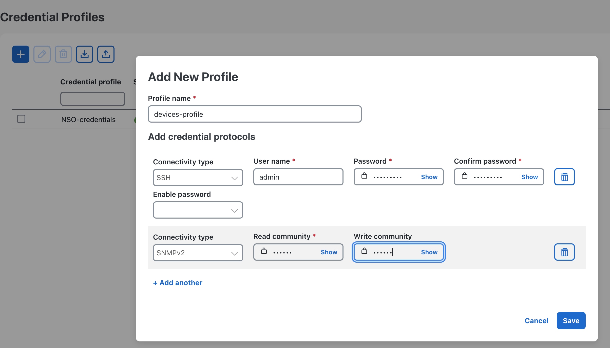
CWPassword

Password to log into Cisco Crosswork. When setting up a VM, ensure the password is strong and meets the following criteria:

  • It must be at least 8 characters long and include uppercase and lowercase letters, numbers, and at least one special character.

  • The following special characters are not allowed: backslash (\), single quote ('), or double quote (").

  • Avoid using passwords that resemble dictionary words (e.g., "Pa55w0rd!") or relatable words. While such passwords may meet the specified criteria, they are considered weak and will be rejected, resulting in a failure to set up the VM.
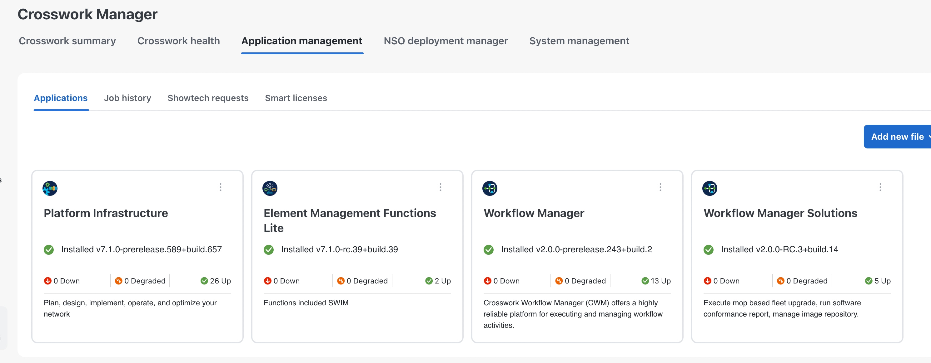
VMSize

Size of the VM. Crosswork supports both the "XLarge" and "Large" profiles. For Fleet Upgrade deployments, specify the "XLarge" profile.

VMName

Name of the VM.

NodeType

Indicates the type of VM. Choose Hybrid.

IsSeed

Set to "True".

InitNodeCount

Set value to 1.

InitMasterCount

Set value to 1.

BackupMinPercent

Minimum percentage of the data disk space to be used for the size of the backup partition. The default value is 35 (valid range is from 1 to 80).

Please use the default value unless recommended otherwise.

Note


The final backup partition size will be calculated dynamically. This parameter defines the minimum.

ThinProvisioned

Set to false for production deployments.

SchemaVersion

The configuration Manifest schema version. This indicates the version of the installer to use with this template.

Schema version should map to the version packaged with the sample template in the installer tool on cisco.com. You should always build a new template from the default template provided with the release you are deploying, as template requirements may change from one release to the next.

LogFsSize

Log partition size (in gigabytes). Minimum value is 20 GB and Maximum value is 1000 GB.

If left blank, the default value (20 GB) is selected.

EnableSkipAutoInstallFeature

Pods marked as "skip auto install" will not be brought up unless explicitly requested by a dependent application or pod. By default, the value is set as "False".

For Fleet Upgrade deployment, you must set the value as "True".

Note

 
  • If left blank, the default value ("False") is automatically selected.

  • This parameter accepts a string value, so be sure to enclose the value in double quotes.

EnforcePodReservations

Enforces minimum resource reservations for the pod. If left blank, the default value ("True") is selected.

This parameter accepts a string value, so be sure to enclose the value in double quotes.

K8sServiceNetwork

The network address for the kubernetes service network. By default, the CIDR range is fixed to '/16'.

K8sPodNetwork

The network address for the kubernetes pod network. By default, the CIDR range is fixed to '/16'.

IgnoreDiagnosticsCheckFailure

Used to set the system response in case of a diagnostic-check failure. If set to "False", the installation will terminate if the diagnostic check reports an error. If set to "True", the diagnostic check will be ignored, and the installation will continue.

The default value is "False". Cisco recommends that you leave the value set to "False" whenever you are installing in a production environment. If the installation is failing with this setting, contact Cisco Customer Experience.

This parameter accepts a string value, so be sure to enclose the value in double quotes.

Note

 
  • The log files (diagnostic_stdout.log and diagnostic_stderr.log) can be found at /var/log. The result from each diagnostic execution is kept in a file at /home/cw-admin/diagnosis_report.txt.

  • Use diagnostic all command to invoke the diagnostic manually on day N.

  • Use diagnostic history command to view previous test report.

ManagementVIPName

Name of the Management Virtual IP for the Crosswork VM. This is an optional parameter used to reach the Crosswork Management VIP via a DNS name. If this parameter is used, the corresponding DNS record must exist in the DNS server.

DataVIPName

Name of the Data Virtual IP for the Crosswork VM. This is an optional parameter used to reach the Crosswork Data VIP via a DNS name. If this parameter is used, the corresponding DNS record must exist in the DNS server.

EnableHardReservations

Determines the enforcement of VM CPU and Memory profile reservations. This is an optional parameter and the default value is "True", if not explicitly specified. This parameter accepts a string value, so be sure to enclose the value in double quotes.

If set as "True", the VM's resources are provided exclusively. In this state, the installation will fail if there are insufficient CPU cores, memory or CPU cycles.

If set as "False" (only set for lab installations), the VM's resources are provided on best efforts. In this state, insufficient CPU cores can impact performance or cause installation failure.

ManagerDataFsSize

This parameter is applicable only when installing with the Docker installer tool.

Refers to the data disk size for the Crosswork node (in gigabytes). This is an optional parameter and the default value is 485 (valid range is from 485 to 8000), if not explicitly specified.

Please use the default value unless recommended otherwise.

RamDiskSize

Size of the RAM disk.

This parameter is only used for lab installations (value must be at least 2). When a non-zero value is provided for RamDiskSize, the HSDatastore value is not used.

Timezone

Enter the timezone name. The name must be a standard IANA "TZ" timezone name in English (for example, "America/Chicago"). You can find the standard IANA timezone description list at https://data.iana.org/time-zones/tzdb-2021a/zone1970.tab.

This is an optional parameter. If left blank, the default value (UTC) is selected. This parameter accepts a string value, so be sure to enclose the value in double quotes.

VMware parameters

If you plan to specify a VMware deployment, you will need to configure the following parameters in your VMware GUI options or VMware template.

Table 5. VMware GUI or template parameters

Parameter Name

Description

VCenterAddress

The vCenter IP or host name.

VCenterUser

The username needed to log into vCenter.

VCenterPassword

The password needed to log into vCenter.

DCname

The name of the Data Center resource to use.

Example: DCname = "WW-DCN-Solutions"

MgmtNetworkName

The name of the vCenter network to attach to the VM's Management interface.

This network must already exist in VMware or the installation will fail.

DataNetworkName

The name of the vCenter network to attach to the VM's Data interface.

This network must already exist in VMware or the installation will fail.

Host

The ESXi host, or ONLY the vCenter VM/resource group name where the VM is to be deployed.

The primary option is to use the host IP or name (all the hosts should be under the data center). If the hosts are under a VM in the data center, only provide the VM name (all hosts within the VM will be picked up).

The subsequent option is to use a resource group. In this case, a full path should be provided.

Example: Host = "Main infrastructure/Resources/00_trial"

Datastore

The datastore name available to be used by this host or resource group.

The primary option is to use host IP or name. The subsequent option is to use a resource group.

Example: Datastore = "SDRS-DCNSOL-prodexsi/bru-netapp-01_FC_Prodesx_ds_15"

HSDatastore

The high speed datastore available for this host or resource group.

When not using a high speed data store, set to same value as Datastore.

Cw_VM_Image

The name of Crosswork VM image in vCenter.

This value is set as an option when running the installer tool and does not need to be set in the template file.

HostedCwVMs

The ID of the VM to be hosted by the ESXi host or resource.

Dual-Stack Parameters

If you plan to specify a dual-stack deployment, you will need to configure the following IPv4 and IPv6 versions of values for the following Management, Data, and DNS parameters.

  • ManagementIPv4Address, ManagementIPv6Address

  • ManagementIPv4Netmask, ManagementIPv6Netmask

  • ManagementIPv4Gateway, ManagementIPv6Gateway

  • ManagementVIPv4, ManagementVIPv6

  • DataIPv4Address, DataIPv6Address

  • DataIPv4Netmask, DataIPv6Netmask

  • DataIPv4Gateway, DataIPv6Gateway

  • DataVIPv4, DataVIPv6

  • DNSv4, DNSv6

Install Crosswork on VMware using vSphere

Follow these steps to deploy Crosswork on a single VM using the VMware vSphere user interface.

Before you begin

Ensure that:


Attention


The download file names given in this topic are subject to change. You can always find the latest versions by pointing your browser to https://software.cisco.com/download/home and searching for Crosswork Network Controller > All Release.


Procedure


Step 1

Install a supported version of VMware ESXi on the machine you plan to use as the Crosswork server.

Step 2

From Cisco Software Central, download the latest version of the Cisco Crosswork platform image file to a storage location on the same system: cnc-advantage-single-node-deployment-7.1.0-48.ova.

Step 3

With VMware ESXi running, log into the VMware vSphere Web Client. On the left navigation pane, choose the ESXi host where you want to deploy the VM.

Step 4

In the vSphere UI, go to Host > Configure > Networking > Virtual Switches and select the virtual switch for the Management Network that will be used to access the UI of the VM. In the virtual switch, select Edit > Security, and configure the following DVS port group properties:

  • Set Promiscuous mode as Reject

  • Set MAC address changes as Reject

Confirm the settings and repeat the process for the virtual switch that will be used for the Data Network.

Step 5

Review and confirm that your network settings meet the requirements.

Ensure that the networks that you plan to use for Management Network and Data network are connected to the host. Contact your Cisco Experience team for assistance.

Step 6

Choose Actions > Deploy OVF Template.

Caution


The default VMware vCenter deployment timeout is 15 minutes. If vCenter times out during deployment, the resulting VM will not be bootable. To prevent this, we recommend that you document the choices (such as IP address, gateway, DNS server, etc.) so that you can enter the information quickly and avoid any issues with the VMware configuration.

Step 7

The VMware Deploy OVF Template window appears, with the first step, 1 - Select an OVF template, highlighted. Click Choose Files to navigate to the location where you downloaded the OVA image file and select it. Once selected, the file name is displayed in the window.

Step 8

Click Next. The Deploy OVF Template window is refreshed, with 2 - Select a name and folder now highlighted. Enter a name and select the respective data center for the Cisco Crosswork VM you are creating.

We recommend that you include the Cisco Crosswork version and build number in the name, for example: Cisco Crosswork 7.1 Build 152.

Step 9

Click Next. The Deploy OVF Template window is refreshed, with 3 - Select a compute resource highlighted. Select the host for your Cisco Crosswork VM.

Step 10

Click Next. The VMware vCenter Server validates the OVA. Network speed will determine how long validation takes. After the validation is complete, the Deploy OVF Template window is refreshed, with 4 - Review details highlighted.

Step 11

Review the OVF template that you are deploying. This information is gathered from the OVF, and cannot be modified.

Note


You may see alerts regarding the OVF package containing advanced configuration options and/or about trusted certificates. These are common and you can safely select the "Ignore" option.

Step 12

Click Next. The Deploy OVF Template window is refreshed, with 5 - License agreements highlighted. Review the End User License Agreement and if you agree, click the I accept all license agreements checkbox. Otherwise, contact your Cisco Experience team for assistance.

Step 13

Click Next The Deploy OVF Template window is refreshed, with 6 - Configuration highlighted. Choose the desired deployment configuration.

Figure 1. Select a deployment configuration

Step 14

Click Next. The Deploy OVF Template window is refreshed, with 7 - Select Storage highlighted. Choose the relevant option from the Select virtual disk format drop-down list. From the table, choose the datastore you want to use, and review its properties to ensure there is enough available storage.

Figure 2. Select Storage

Note


For production deployment, choose the Thick Provision Eager Zeroed option because this will preallocate disk space and provide the best performance. For lab purposes, we recommend the Thin Provision option because it saves disk space.

Step 15

Click Next. The Deploy OVF Template window is refreshed, with 8 - Select networks highlighted. From the Destination Network drop-down list, select the proper networks for the Management Network and the Data Network.

Figure 3. Select networks

Step 16

Click Next. The Deploy OVF Template window is refreshed, with 9 - Customize template highlighted.

  1. Expand the Management Network settings. Provide information for the IPv4 and/or IPv6 deployment (as per your selection) such as IP address, IP netmask, IP gateway, virtual IP address, and virtual IP DNS name.

  2. Expand the Data Network settings. Provide information for the IPv4 and/or IPv6 deployment (as per your selection) such as IP address, IP netmask, IP gateway, virtual IP address, and virtual IP DNS name.

  3. Expand the Deployment Credentials settings. Enter relevant values for the VM Username and Password.

    Note


    Avoid using passwords that resemble dictionary words (for example, 'Pa55w0rd!') or easily guessable patterns. While such passwords might meet the initial criteria, they are considered weak and could cause the VM setup to fail without a clear explanation. To ensure a successful installation, use a complex password with a minimum of 8 characters that combines uppercase and lowercase letters, numbers, and special characters in a non-predictable sequence.

  4. Expand the DNS and NTP Servers settings. According to your deployment configuration (IPv4 and/or IPv6), the fields that are displayed are different. Provide information in the following three fields:

    • DNS IP Address: The IP addresses of the DNS servers you want the Cisco Crosswork server to use. Separate multiple IP addresses with spaces.

    • NTP Servers: The IP addresses or host names of the NTP servers you want to use. Separate multiple IPs or host names with spaces.

    • DNS Search Domain: The name of the DNS search domain.

    • Timezone: Enter the timezone details. Default value is UTC.

    Note


    The DNS and NTP servers must be reachable using the network interfaces you have mapped on the host. Otherwise, the configuration of the VM will fail.

  5. Expand the Disk Configuration settings. Provide relevant values for these fields:

    • Logfs Disk Size

    • Datafs Disk Size

    • Corefs Partition Size

    • High Speed Disk Size

    • Minium backup partition size

    The default disk configuration settings should work for most environments. Change the settings only if you are instructed to by the Cisco Customer Experience team.

  6. Expand Crosswork Configuration and enter your legal disclaimer text (users will see this text if they log into the CLI).

  7. Expand Crosswork Cluster Configuration. Provide relevant values for these fields:

    • VM Type: Choose Hybrid.

    • Cluster Seed node: Choose True.

    • Crosswork Management Cluster Virtual IP: Enter virtual IP of the management network.

    • Crosswork Management Cluster Virtual IP Name: Enter DNS hostname of virtual IP interface of the management network.

    • Crosswork Data Cluster Virtual IP: Enter virtual IP of the data network.

    • Crosswork Data Cluster Virtual IP Name: Enter DNS hostname of virtual IP interface of the data network.

    • Initial hybrid node count: Set to 1.

    • Initial total node count: Set to 1.

    • Location of VM: Enter the geographical location of VM.

    • Disclaimer: Enter your legal disclaimer text (users will see this text if they log into the CLI).

    • Installation type: Not applicable to single VM deployment. Do not select any checkbox.

    • Enable Skip Auto Install Feature: Set to True.

    • Auto Action Manifest Definition: Use the default value (Empty).

    • Product specific definition: Enter the product specific definition.

    • Ignore Diagnostic Failure?: Use the default value (False).

Step 17

Click Next. The Deploy OVF Template window is refreshed, with 10 - Ready to Complete highlighted.

Step 18

Review your settings and then click Finish if you are ready to begin deployment. Wait for the deployment to finish before continuing. To check the deployment status:

  1. Open a VMware vCenter client.

  2. In the Recent Tasks tab of the host VM, view the status of the Deploy OVF template and Import OVF package jobs.

Step 19

Once the deployment is completed, right-click on the VM and select Edit Settings. The Edit Settings dialog box is displayed. Under the Virtual Hardware tab, update these attributes:

  • VM profile: XLarge

  • CPU: 24

  • Memory: 128 GB

Click OK to save the changes.

Step 20

Power on the Crosswork VM. To power on, expand the host’s entry, click the Cisco Crosswork VM, and then choose Actions > Power > Power On.

The time taken to create the VM can vary based on the size of your deployment profile and the performance characteristics of your hardware.


Install Crosswork on VMware using Docker

Follow these steps to deploy Crosswork on a single VM using the Docker installer tool.

Before you begin

Ensure that:

During and after the install, note that:

  • The edited template in the /data directory contains sensitive information (VM passwords and the vCenter password). It will be your responsibility to manage access to this content. Cisco recommends that you store the templates used for your install in a secure environment or edit them to remove the passwords.

  • During the install, the files install.log, install_tf.log, and .tfstate will be created and stored in the /data directory. If you encounter trouble with the installation and must open a case with the Cisco Customer Experience team, please remember to provide these files to the team.

  • The install script is safe to run multiple times. Upon error, input parameters can be corrected and re-run. You must remove the install.log, install_tf.log, and tfstate files before each re-run. Running the Docker installer tool multiple times may result in the deletion and re-creation of VMs.

  • In order to change install parameters or to correct parameters following installation errors, it is important to distinguish whether the installation has managed to deploy the VM successfully or not. You can detect that a VM was deployed successfully if the installer provides output similar to the following:

    vsphere_virtual_machine.crosswork-IPv4-vm["1"]: Creation complete after 2m50s [id=4214a520-c53f-f29c-80b3-25916e6c297f]
  • If you use the same installer tool for multiple Crosswork installations, it is important to run the tool from different local directories, allowing for the deployment-state files to be independent. The simplest way to do this is to create a local directory on the host for each deployment, and map each new local directory to the container accordingly.

Be aware that:

  • Docker version 19 or higher is required while using the installer tool. For more information on Docker, see https://docs.docker.com/get-docker/.

  • Crosswork installed on a single VM does not currently support VMware vCenter storage folders or datastores organized under a virtual folder structure. Ensure that the datastores referenced are not grouped under a folder.


Attention


The download file names given in this topic are subject to change. You can always find the latest versions by pointing your browser to https://software.cisco.com/download/home and searching for Crosswork Network Controller > All Release.


Procedure


Step 1

In your Docker-capable machine, create a directory where you will store everything you will use during this installation.

Note


If you are using a Mac, ensure that the directory name is in lower case.

Step 2

From https://software.cisco.com/download/home, download the Crosswork platform installer bundle (.tar.gz) and OVA image file to the directory you created previously: cnc-advantage-single-node-docker-deployment-7.1.0-48.tar.gz and cnc-advantage-single-node-deployment-7.1.0-48.ova.

Step 3

Use the following command to extract the installer bundle:

tar -xvf cnc-advantage-single-node-docker-deployment-7.1.0-48.tar.gz

The contents of the installer bundle are unzipped to a new directory (e.g. cnc-advantage-single-node-docker-deployment-7.1.0-48). The extracted files will contain the installer image (cw-na-cnc-advantage-svm-installer-7.1.0-48-releasecnc710-250606.tar.gz) and files necessary to validate the image.

Step 4

Review the contents of the README file to understand everything that is in the package and how it will be validated in the following steps.

Step 5

If you don't already know the version of python installed on your workstation, use the following command to detect it: python --version

Step 6

Use the following command to verify the signature of the installer image:

If you are using Python 2.x, use the following command to validate the file:

python cisco_x509_verify_release.py -e filename.cer -i filename.tar.gz -s Signaturefilename.tar.gz
-v dgst -sha512

If you are using Python 3.x, use the following command to validate the file:

python3 cisco_x509_verify_release.py3 -e filename.cer -i filename.tar.gz -s Signaturefilename.tar.gz
-v dgst -sha512

Step 7

Use the following command to load the installer image file into your Docker environment.

docker load -i filename.tar.gz

For example:

docker load -i cw-na-cnc-advantage-svm-installer-7.1.0-48-releasecnc710-250606.tar.gz

Step 8

Run the Docker image list or Docker images command to get the "image ID" (which is needed in the next step).

For example:

docker images

The result will be similar to the following: (the output section we will need is underlined for clarity)

My Machine% docker images
REPOSITORY                        TAG                                                     IMAGE ID       CREATED        SIZE
dockerhub.cisco.com/cw-installer  cw-na-cnc-advantage-svm-7.1.0-48-releasecnc710-250606   a4570324fad30  7 days ago     276MB

Note


Pay attention to the "CREATED" time stamp in the table presented when you run docker images, as you may have other images present from the installation of prior releases. If you want to remove these, use the docker image rm {image id} command.

Step 9

Launch the Docker container using the following command:

docker run --rm -it -v `pwd`:/data image id of the installer container

To run the image loaded in our example, you would use the following command:

docker run --rm -it -v `pwd`:/data a4570324fad30

Note

 
  • You do not have to enter the full image ID value. Docker requires only enough of the image ID to uniquely identify the image you want to use for the installation. In our example, a command like docker run --rm -it -v `pwd`:/data a45 would also be adequate.

  • In the above command, we are using the backtick (`). Do not use the single quote or apostrophe ('), as this means something very different to the shell. By using the backtick, the template and OVA files will be stored in the current directory where you are located on your local disk when you run the commands, instead of inside the container.

  • When deploying an IPv6 setup, the installer needs to run on an IPv6-enabled container/VM. This requires additionally configuring the Docker daemon before running the installer, using the following method:

    • Linux hosts only: Run the Docker container in host networking mode by adding the –network host flag to the docker run command:

      docker run --network host remainder of docker run options
  • Centos/RHEL hosts: These hosts, by default, enforce a strict SELinux policy which does not allow the installer container to read from or write to the mounted data volume. On such hosts, run the Docker volume command with the Z option, as shown below:

    docker run --rm -it -v `pwd`:/data:Z remainder of docker run options

Note


The Docker command provided will use the current directory to read the template and the OVA files, and to write the log files used during the install. If you encounter either of the following two errors, you should move the files to a directory where the path is in lowercase (all lowercase, no spaces or other special characters). Then navigate to that directory and rerun the installer.

Error 1:

% docker run --rm -it -v `pwd`:/data a45
docker: invalid reference format: repository name must be lowercase.
See 'docker run --help'

Error 2:

docker: Error response from daemon: Mounts denied: approving /Users/Desktop: file does not exist
ERRO[0000] error waiting for container: context canceled

Step 10

Navigate to the directory with the VMware template:

cd /opt/installer/deployments/7.1.0/vcentre

Step 11

Copy the template file found under /opt/installer/deployments/7.1.0/vcentre/deployment_template_tfvars to the /data folder using a different name.

For example: cp deployment_template_tfvars /data/deployment.tfvars

For the rest of this procedure, we will use the file name deployment.tfvars in all the examples.

Step 12

Using a text editor of your choice, open the template file you copied to the /data directory and edit it to match the properties for your planned deployment.

For reference, here is an example deployment.tfvars, edited using sample parameter values. You must use the values you gathered for your deployment, as specified in Gather installation parameter values

Cw_VM_Image = ""    # Line added automatically by installer.
ClusterIPStack        = "IPv4"
ManagementVIP         = "10.78.103.198"
ManagementIPNetmask   = "255.255.255.0"
ManagementIPGateway   = "10.78.103.1"
DataVIP               = "192.168.100.198"
DataIPNetmask         = "255.255.255.0"
DataIPGateway         = "0.0.0.0"
DNS                   = "72.163.128.140"
DomainName            = "cisco.com"
CWPassword            = "*****!"
VMSize                = "XLarge"
NTP                   = "ntp.esl.cisco.com"
Timezone              = "Asia/Calcutta"
EnableSkipAutoInstallFeature = "True"
CwVMs = {
    "0" = {
      VMName              = "SVM198",
      ManagementIPAddress = "10.78.103.197",
      DataIPAddress       = "192.168.100.197",
      NodeType            = "Hybrid"
    }
}
VCenterDC = {
  VCenterAddress = "10.64.80.220",
  VCenterUser = "vcenterUsername",
  VCenterPassword = "vCenterPassword",
  DCname = "Crosswork-Single-VM",
  MgmtNetworkName = "VM Network",
  DataNetworkName = "CW-7.1-VLAN21",
  VMs = [
      {
        HostedCwVMs = ["0"],
        Host = "10.78.103.62",
        Datastore = "5.2TB-SSD-62-2",
        HSDatastore="5.2TB-SSD-62-2"
      }
  ]
}
SchemaVersion = "7.1.0"

Step 13

From the /opt/installer directory, run the installer.

./cw-installer.sh install -m /data/template file name -o /data/filename.ova

For example:

./cw-installer.sh install -m /data/deployment.tfvars -o /data/cnc-advantage-single-node-deployment-7.1.0-48.ova

Step 14

The installer will display the End User License Agreement (EULA). Read, and then enter "yes" if you accept the EULA. Otherwise, exit the installer and contact your Cisco representative.

Step 15

When prompted, enter "yes" to begin the installation operation.

Step 16

When the installation operation exits, confirm the successful installation or re-run a failed installation, as follows:

It is not uncommon to see warnings like the following during the install:

Warning: Line 119: No space left for device '8' on parent controller '3'.
Warning: Line 114: Unable to parse 'enableMPTSupport' for attribute 'key' on element 'Config'.

You can ignore warnings like this if the install process proceeds to a successful conclusion, as indicated by the sample output below:

Sample output for successful installation:

cw_vms = .......
INFO: Copying day 0 state inventory to CW
INFO: Waiting for deployment status server to startup on ip address. Elapsed time 0s, retrying in 30s
Crosswork deployment status available at http://ipaddress:30602/d/NK1bwVxGk/crosswork-deployment-readiness?orgId=1&refresh=10s&theme=dark 
Once deployment is complete login to Crosswork via: https://ipaddress:30603/#/logincontroller 
INFO: Cw Installer operation complete.

If the installation fails:

  1. Open a support case with Cisco. Include with the case copies of the error messages reported during the installation. Remember to include copies of the following .log files created in the /data directory (and the local directory where you launched the installer Docker container) with the case: install.log, install_tf.log, and .tfstate

  2. The two most common reasons for the install to fail are a password that is not adequately complex, and errors in the template file, such as a mistyped IP address. If the installer fails due to errors like this, correct the error and rerun the install script. Remember to delete the .log files before re-running the installation.


For KVM deployments: Configure network bridges or SRIOV

The following procedures are relevant only if you are planning a KVM deployment. Ignore them if you are conducting a VMware deployment.

Crosswork needs a 10Gb interface for all the data layer communications to support functionality at scale. You may choose any networking configuration which can provide 10G throughput.

The following two topics explain how to enable network bridges and SRIOV network configuration, which will allow you to meet this requirement for a 10Gb interface on a KVM deployment. Note that, for a KVM deployment, you must either Configure network bridges or Configure SRIOV, but not both.

Configure network bridges

A network bridge acts like a virtual network switch, allowing multiple network interfaces to communicate as if they are on the same physical network.

Follow these steps to configure network bridges for a KVM deployment. Ignore this procedure if you are are planning to Configure SRIOV for your KVM deployment, or are conducting a VMware deployment.

Procedure


Step 1

Create a new network connection of type "bridge" with the interface name intMgmt and assign it the connection name intMgmt.

nmcli connection add type bridge ifname intMgmt con-name intMgmt

Step 2

Add a new bridge-port connection, associating the physical network interface <interface1> with the previously created bridge intMgmt.

nmcli connection add type bridge-port ifname <interface1> controller intMgmt

Step 3

Assign IP address to the bridge.

nmcli connection modify intMgmt ipv4.addresses <IPv4-address>/<subnet-mask>

Step 4

Bring up the intMgmt network connection.

nmcli connection up intMgmt

Step 5

Create another network bridge connection with the interface name intData and assign it the connection name intData.

nmcli connection add type bridge ifname intData con-name intData

Step 6

Add a bridge-port connection, associating the physical network interface <interface2> with the previously created bridge intData.

nmcli connection add type bridge-port ifname <interface2> controller intData

Step 7

Assign IP address to intData.

nmcli connection modify intData ipv4.addresses <IPv4-address>/<subnet-mask>

Step 8

Bring up the intData network connection.

nmcli connection up intData

Configure SRIOV

SRIOV allows a single physical network interface to be shared among multiple VMs by creating multiple Virtual Functions (VFs).

Follow these steps to configure SRIOV for a KVM deployment. Ignore this procedure if you are planning to Configure network bridges for your KVM deployment, or are conducting a VMware deployment.

Procedure


Step 1

Open the rc.local file in the vi editor.

vi /etc/rc.d/rc.local

Step 2

Set the number of VFs for the network interfaces based on your requirement. For instance, in a Cisco Crosswork Planning single VM installation, you need a minimum of two network interfaces—one for management and the other for data. Two VFs are configured for each interface by default. You may also configure additional VFs for future scalability needs.

For example, to set the number of VFs to 2 for each <interface1> and <interface2>, use these commands. In this example, <interface1> refers to the management interface and <interface2> refers to the data interface.

echo 2 > /sys/class/net/<interface1>/device/sriov_numvfs
echo 2 > /sys/class/net/<interface2>/device/sriov_numvfs

Step 3

Change the permissions of the rc.local file to make it executable.

chmod +x /etc/rc.d/rc.local

Step 4

If any of the interfaces are configured over the VLAN, set the VLAN IDs to the interfaces.

ip link set <interface1> vf 0 vlan <vlanid>
ip link set <interface2> vf 1 vlan <vlanid>

Step 5

Save the changes and reboot the system.

Step 6

List all the PCI devices for all the virtual functions in a tree format. This is useful for verifying the setup and ensuring that the VFs are correctly recognized by the KVM hypervisor.

virsh nodedev-list -\-tree

In this procedure, since we set the number of VFs as 2 in Step 2, two VFs for each management interface and data interface are created. As a result, a total of four PCI devices are generated: two for management and two for data.

This PCI device information is used during the installation process with SRIOV (Step 4 of Install Crosswork on KVM).


Install Crosswork on KVM

Follow these steps to deploy Crosswork on a single VM on KVM RHEL.


Note


The time taken to create the VM can vary based on the size of your deployment profile and the performance characteristics of your hardware.


Before you begin

Ensure that:


Attention


The download file names given in this topic are subject to change. You can always find the latest versions by pointing your browser to https://software.cisco.com/download/home and searching for Crosswork Network Controller > All Release.


Procedure


Step 1

Prepare a config IOS file ovf-env.xml) to use when installing the Crosswork VM.

Use the following example template to prepare the ovf-env.xml file:

<Environment
     xmlns="http://schemas.dmtf.org/ovf/environment/1"
     xmlns:xsi="http://www.w3.org/2001/XMLSchema-instance"
     xmlns:oe="http://schemas.dmtf.org/ovf/environment/1"
     xmlns:ve="http://www.vmware.com/schema/ovfenv"
     oe:id=""
   <PlatformSection>
      <Kind>KVM</Kind>
      <Version>7.1.0</Version>
      <Vendor>KVM</Vendor>
      <Locale>en</Locale>
   </PlatformSection>
    <PropertySection>
         <Property oe:key="CWPassword" oe:value="**********"/>
         <Property oe:key="CWUsername" oe:value="cw-admin"/>
         <Property oe:key="ClusterCaKey" oe:value=""/>
         <Property oe:key="ClusterCaPubKey" oe:value=""/>
         <Property oe:key="CwInstaller" oe:value="False"/>
         <Property oe:key="DNSv4" oe:value="171.70.168.183"/>
         <Property oe:key="DNSv6" oe:value="::0"/>
         <Property oe:key="DataIPv4Address" oe:value="192.168.5.48"/>
         <Property oe:key="DataIPv4Gateway" oe:value="192.168.5.1"/>
         <Property oe:key="DataIPv4Netmask" oe:value="255.255.255.0"/>
         <Property oe:key="DataIPv6Address" oe:value="::0"/>
         <Property oe:key="DataIPv6Gateway" oe:value="::1"/>
         <Property oe:key="DataIPv6Netmask" oe:value="64"/>
         <Property oe:key="DataPeerIPs" oe:value=""/>
         <Property oe:key="DataVIP" oe:value="192.168.5.51"/>
         <Property oe:key="DataVIPName" oe:value=""/>
         <Property oe:key="Deployment" oe:value="cw_ipv4"/>
         <Property oe:key="Disclaimer" oe:value="Cisco Crosswork"/>
         <Property oe:key="Domain" oe:value="cisco.com"/>
         <Property oe:key="EnableSkipAutoInstallFeature" oe:value="True"/>
         <Property oe:key="EnforcePodReservations" oe:value="True"/>
         <Property oe:key="IgnoreDiagnosticsCheckFailure" oe:value="True"/> 
         <Property oe:key="InitMasterCount" oe:value="1"/>
         <Property oe:key="InitNodeCount" oe:value="1"/>
         <Property oe:key="IsSeed" oe:value="True"/>
         <Property oe:key="K8Orch" oe:value=""/>
         <Property oe:key="K8sPodNetworkV4" oe:value="10.244.0.0"/>
         <Property oe:key="K8sServiceNetworkV4" oe:value="10.96.0.0"/>
         <Property oe:key="ManagementIPv4Address" oe:value="10.19.70.148"/>
         <Property oe:key="ManagementIPv4Gateway" oe:value="10.19.70.1"/>
         <Property oe:key="ManagementIPv4Netmask" oe:value="255.255.255.0"/>
         <Property oe:key="ManagementIPv6Address" oe:value="::0"/>
         <Property oe:key="ManagementIPv6Gateway" oe:value="::1"/>
         <Property oe:key="ManagementIPv6Netmask" oe:value="112"/>
         <Property oe:key="ManagementVIP" oe:value="10.19.70.151"/>
         <Property oe:key="ManagementVIPName" oe:value=""/>
         <Property oe:key="ManagerPeerIPs" oe:value=""/>
         <Property oe:key="NTP" oe:value="ntp.esl.cisco.com"/>
         <Property oe:key="Timezone" oe:value="US/Pacific"/>
         <Property oe:key="VMLocation" oe:value="default"/>
         <Property oe:key="VMType" oe:value="Hybrid"/>
         <Property oe:key="bckup_min_percent" oe:value="35"/>
         <Property oe:key="corefs" oe:value="18"/>
         <Property oe:key="ddatafs" oe:value="485"/>
         <Property oe:key="logfs" oe:value="20"/>
         <Property oe:key="ramdisk" oe:value="0"/>
         <Property oe:key="ssd" oe:value="15"/>
         <Property oe:key="VMSize" oe:value="XLarge"/>
         <Property oe:key="ThinProvisioned" oe:value="False"/>
         <Property oe:key="UseNonDefaultCalicoBgpPort" oe:value="False"/>
         <Property oe:key="bootOptions.efiSecureBootEnabled" oe:value="True"/>
   </PropertySection>
</Environment>

Step 2

Update the ovf-env.xml file you created using the parameter values you gathered for your KVM deployment (see General parameters).

$ cat ovf-env.xml

Step 3

Generate the IOS file.

$ mkisofs -R -relaxed-filenames -joliet-long -iso-level 3 -l -o cnc1.iso ovf-env.xml

Note


In the above command, cnc1 is the host name of the Cisco Crosswork VM.

Step 4

From https://software.cisco.com/download/home, download the latest version of the Cisco Crosswork platform qcow2.tar.gz file to a storage location on your KVM host: cnc-advantage-single-node-deployment-7.1.0-48-qcow.tar.gz.

Step 5

Extract the tar.gz file using the following command:

tar -xvf cnc-advantage-single-node-deployment-7.1.0-48-qcow2.tar.gz

This command creates three qcow2 files:

  • cnc-advantage-single-node-deployment-7.1.0-48_dockerfs.qcow2

  • cnc-advantage-single-node-deployment-7.1.0-48_extrafs.qcow2

  • cnc-advantage-single-node-deployment-7.1.0-48_rootfs.qcow2

Step 6

Navigate to the required installation folder and create three disks.

cd cnc1/
qemu-img create -f qcow2 disk3 20G
qemu-img create -f qcow2 disk4 485G
qemu-img create -f qcow2 disk6 15G
ls -1
cw_dockerfs.vmdk.qcow2
cw_extrafs.vmdk.qcow2
cw_rootfs.vmdk.qcow2
disk3
disk4
disk6

Step 7

Install the Crosswork VM using either network bridge or SRIOV.

In these examples, cnc1 is the host name of the Crosswork VM.

  • Using network bridge:

    virt-install --boot uefi --boot hd,cdrom --connect qemu:///system --virt-type kvm --name cnc1 --ram 98304 --vcpus 12 --os-type linux --disk path=cnc-advantage-single-node-deployment-7.1.0-48_rootfs.qcow2,format=qcow2,bus=scsi --disk path=cnc-advantage-single-node-deployment-7.1.0-48_dockerfs.qcow2,format=qcow2,bus=scsi --disk path=disk3,format=qcow2,bus=scsi --disk path=disk4,format=qcow2,bus=scsi --disk path=cnc-advantage-single-node-deployment-7.1.0-48_extrafs.qcow2,format=qcow2,bus=scsi --disk path=disk6,format=qcow2,bus=scsi --disk=cnckvm.iso,device=cdrom,bus=scsi --import --network bridge=intMgmt,model=virtio --network bridge=intData,model=virtio --noautoconsole --os-variant ubuntu22.04 --graphics vnc,listen=0.0.0.0
  • Using SRIOV:

    virt-install --boot uefi --boot hd,cdrom --connect qemu:///system --virt-type kvm --name cnc1 --ram 98304 --vcpus 12 --cpu host-passthrough --disk path=cw_rootfs.vmdk.qcow2,format=qcow2,bus=scsi --disk path=cw_dockerfs.vmdk.qcow2,format=qcow2,bus=scsi --disk path=disk3,format=qcow2,bus=scsi --disk path=disk4,format=qcow2,bus=scsi --disk path=cw_extrafs.vmdk.qcow2,format=qcow2,bus=scsi --disk path=disk6,format=qcow2,bus=scsi --disk=cnc1.iso,device=cdrom,bus=scsi --import --network none --host-device=pci_0000_01_10_0 --host-device=pci_0000_01_10_0 --os-variant ubuntu-lts-latest &
    

NSO package pre-installation tasks

Before installing the CWM Solutions packages for NSO, you must ensure that additional Python packages are installed on NSO and that NSO supports REST. CWM Solutions can use both SSL and HTTPS, so you can choose to enable both in the REST configuration if needed. You will need to install SSL certificate files and specify their location in the RESTCONF configuration if you want to enable SSL.

Before you begin

Ensure that you have met the basic requirements for the NSO installation, as explained in Meet installation requirements. If you plan to enable HTTPS/SSL as part of the REST configuration, Cisco recommends that you create and install SSL certificate and key files in the NCS configuration directory before completing this task.

Procedure


Step 1

Install the following Python packages on the NSO server:

~$ sudo pip install textfsm
~$ sudo pip install jinja2
~$ sudo pip instapp pyyaml
~$ sudo pip install pycryptodome

Step 2

Edit the NSO ncs.conf file as shown below to enable REST support. The <ssl> block is optional and shown below in italics to distinguish it from REST and other commands. For example:

sudo vi /etc/ncs/ncs.conf
 
 <webui>
    <enabled>true</enabled>
    <transport>

<ssl>
  <enabled>true</enabled>
  <ip>0.0.0.0</ip>
  <port>8888</port>
  <key-file>${NCS_CONFIG_DIR}/ssl/cert/host.key</key-file>
  <cert-file>${NCS_CONFIG_DIR}/ssl/cert/host.cert</cert-file>
  <extra-listen>
    <ip>::</ip>
    <port>8888</port>
  </extra-listen>
      </ssl>
    </transport>
 
    <cgi>
      <enabled>true</enabled>
      <php>
        <enabled>false</enabled>
      </php>
    </cgi>
  </webui>
 
  <restconf>
    <enabled>true</enabled>
  </restconf>

Step 3

When you have finished the edit, save the ncs.conf file and restart NSO. For example:

sudo systemctl restart ncs

Step 4

Using an admin user ID, verify that REST is working correctly on your NSO installation. For example:

admin1@ncs% run show ncs-state rest
ncs-state rest listen ssl
 ip   ::
 port 8888
ncs-state rest listen ssl
 ip   0.0.0.0
 port 8888

Step 5

Specify the following NSO global configuration settings:

admin1@ncs% show devices global-settings
connect-timeout 600;
read-timeout    600;
write-timeout   600;
ssh-algorithms {
    public-key [ ssh-rsa ];
}
trace           pretty;
}

Step 6

Add the ulimit values for the Linux operating system before the commented line #End of file if it’s not already there. For example:

  1. Check the /etc/security/limits.conf file:

    $ grep hard /etc/security/limits.conf
    $ grep soft /etc/security/limits.conf 
  2. If not configured, edit the /etc/security/limits.conf file and add the following lines:

    * soft nproc 65535
     * hard nproc 65535
     * soft nofile 65535
     * hard nofile 65535
     * soft memlock 65535
     * hard memlock 65535 
  3. Run the sysctl -p script to set the parameters.

  4. Log out of the system and log in again to apply the new values.

  5. Verify that the ulimit values for the Linux operating system are applied.

    $ ulimit -a core file size          (blocks, -c) 0 
    data seg size           (kbytes, -d) unlimited 
    scheduling priority             (-e) 0 
    file size               (blocks, -f) unlimited 
    pending signals                 (-i) 95697 
    max locked memory       (kbytes, -l) 65536 
    max memory size         (kbytes, -m) 
    unlimited open files                      (-n) 65535 
    pipe size            (512 bytes, -p) 8 
    POSIX message queues     (bytes, -q) 819200 
    real-time priority              (-r) 0 
    stack size              (kbytes, -s) 8192 
    cpu time               (seconds, -t) 
    unlimited max user processes              (-u) 65535 
    virtual memory          (kbytes, -v) unlimited 
    file locks                      (-x) unlimited 

Step 7

Ensure that the NETCONF Access Control Model (NACM) rule list grants the ncsadmin and Linux users permissions to perform functions on NSO. For example:

admin1@ncs% show nacm
read-default     deny;
write-default    deny;
exec-default     deny;
groups {
    group ncsadmin {
        user-name [ admin1 private ];
    }
    group ncsoper {
        user-name [ public ];
    }
}

For help adding more users, including adding them to auth groups, see the NSO Administration Guide topic Adding a User.


Install the Crosswork Workflow Manager CAPP

Once you have deployed Crosswork on a VMware or KVM virtual machine, you can install the Crosswork Workflow Manager (CWM) application, which is distributed as a Crosswork CAPP.

Before you begin

Ensure that you have deployed Crosswork successfully on your VMware or KVM host. To verify that Crosswork is installed and functional, log in to Crosswork using an administrative ID at https://CrossworkIP:30603/, where CrossworkIP is the IP address on the virtual machine where Crosswork was installed.


Attention


The download file names given in this topic are subject to change. You can always find the latest versions by pointing your browser to https://software.cisco.com/download/home and searching for Crosswork Workflow Manager 2.


Procedure


Step 1

On a remote host accessible by HTTP, HTTPS or SCP from your Crosswork VM host, create a storage directory to contain the download you will use in this procedure.

Step 2

From https://software.cisco.com/download/home, download to the remote host the Cisco Crosswork Workflow Manager Advantage Standalone Platform Deployment file appropriate for the VM deployment you chose:

  • For a VMware deployment: CW-CWM-Solutions-Advantage-2.0.0-14-SVM-7.1.0-48-ova.signed.bin

  • For a KVM deployment: CW-CWM-Solutions-Advantage-2.0.0-14-SVM-7.1.0-48-qcow2.signed.bin

Step 3

Use the following command to extract the tar.gz installer bundle from the appropriate signed.bin file:

sh CW-CWM-Solutions-Advantage-2.0.0-14-SVM-7.1.0-48-ova.tar.gz

or

sh CW-CWM-Solutions-Advantage-2.0.0-14-SVM-7.1.0-48-qcow2.tar.gz

The contents of the installer bundle and files necessary to validate the image are extracted to the same directory on the remote host.

Step 4

Log in to Crosswork using an admin ID and select Administration > Crosswork Manager > Application Management.

Step 5

Click Add new file and select Upload CAPP file (.tar.gz).

Step 6

Using the Add File (.Tar.Gz) page, first select the Protocol you want to use to add the CWM CAPP file to the system. Then:

  1. If you selected URL: Enter the URL for the remote host where the CAPP file is stored (including the path to the tar.gz file), as shown in the following figure. If the Basic Auth checkbox is selected, enter the Username and Password needed to access the remote host.

  2. If you selected SCP: Enter the file's Server path/Location on the remote host, the remote host server's Host name/IP address, the Port, and the login Username and Password.

Step 7

Click Add. You can select the Job History option to monitor the progress of the CAPP file upload.

Step 8

When the upload completes, the Workflow Manager tile appears on the Applications page, indicating that the application is ready to install, as shown in the following figure.

Step 9

Click the More icon (three dots) on the Workflow Manager tile to display the Workflow Manager installation pop up, then click Install. When installation is complete, the Applications Management > Job History tab should display an "Activation Successful" message.

Step 10

Verify successful installation by choosing Administration > Crosswork Manager > Crosswork Health > Workflow Manager. The Microservices tab should list the 10 microservices shown in the following figure, all with Healthy showing in the Status column.


Install the CWM Solutions CAPP

Once you have installed CWM, you can install the CWM-S application, which includes Fleet Upgrade.

Before you begin

Ensure that you have already installed Crosswork Workflow Manager, as explained in Install the Crosswork Workflow Manager CAPP. If you have done this, you will find the Crosswork Workflow Manager Solutions (CWM-S) installer bundle extracted to the same directory on the remote host where you extracted the Crosswork Workflow Manager (CWM) CAPP installer bundle.

Procedure


Step 1

If you have not already done so, log in to Crosswork using an admin ID and select Administration > Crosswork Manager > Application Management.

Step 2

Click Add new file and select Upload CAPP file (.tar.gz).

Step 3

Using the Add File (.Tar.Gz) page, first select the Protocol you want to use to add the CWM Solutions CAPP file to the system. Then:

  1. If you selected URL: Enter the URL for the remote host where the CAPP file is stored (including the path to the tar.gz file), as shown in the following figure. If the Basic Auth checkbox is selected, enter the Username and Password needed to access the remote host.

  2. If you selected SCP: Enter the file's Server path/Location, the server's Host name/IP address, Port, and the login Username and Password.

Step 4

Click Add. You can select the Job History option to monitor the upload while it proceeds.

Step 5

When the addition completes, the Workflow Manager Solutions tile appears on the Applications page at the far right, next to the Workflow Managertile, indicating that the Workflow Manager Solutions application is ready to install.

Step 6

Click the More icon (three dots) on the Workflow Manager Solutions tile to display the installation pop up menu, then click Install.

Step 7

When installation is completed, the Application Management > Job History tab should display an "Activation of application Workflow Manager Solutions Successful" message.

Step 8

Application Management > Applications tab should show that both Workflow Manager and Workflow Manager Solutions are up.

Step 9

Choose Administration > Crosswork Manager > Crosswork Health > Workflow Manager Solutions. The Microservices tab should show all five CWM Solutions microservices are in a Healthy state.

Step 10

Finally, CWM Solutions will add three dynamic service pods to CWM. These are worker pods for the three CWM adapters that CWM Solutions installed automatically. You will find them under Administration > Crosswork Manager > Crosswork Health > Workflow Manager (not under Workflow Manager Solutions).


Create Crosswork credential profiles

Crosswork Credential Profiles store login user names and passwords in a secure fashion. Crosswork uses them to let Fleet Upgrade and Crosswork Providers authenticate when they attempt to access your devices. In this procedure, we will create a credential profile first for the NSO provider and then for the devices.

Before you begin

Ensure that you've already installed CWM Solutions per the instructions in Install the CWM Solutions CAPP.

Procedure


Step 1

Log in to Crosswork and select Device Management > Credential Profiles. Crosswork displays the Credential Profiles list.

Step 2

Create the NSO provider's credential profile as follows:

  1. Click + to add a credential profile for the NSO provider.

  2. Complete the fields on the Add New Profile window as follows:

    In this field...

    Enter or select:

    Profile name

    NSO-Credentials (or any unique name you find meaningful)

    Connectivity type

    SSH

    User name

    The username for an admin user on the NSO server. This user name can be a dedicated CWM Solutions user name with admin privileges that you create on the NSO server. In any case, this admin user name must be one that is in the ncsadmin group on the NSO server.

    Password

    The password for this user name.

    Confirm password

    The same password you entered in Password.

    Enable password

    Leave this field blank.

  3. Click + Add another to display another set of connectivity protocols to add to the same NSO credential profile. This time, select HTTPS as the Connectivity type, and enter the same NSO user and password information for this protocol, just as you did for Step 2b. For example:

  4. When you are finished, click Save to save the NSO credential profile. You should see the Profile name you specified appear on the Credential Profiles list.

Step 3

Repeat Step 2 to create another credential profile for your devices. You will want to add as many device login credentials and protocols (SSH, NETCONF, HTTP, HTTPS) as are appropriate for the devices you intend to manage using CWM Solutions.

The following figure shows how you might create a single device credential profile that serves most purposes for Fleet Upgrade users. You might create multiple credential profiles if you have groups of devices using the same protocols but with different credentials. For example:

Create an NSO provider profile

A Crosswork Provider is a helper application that lets Crosswork perform special functions. Cisco Network Services Orchestrator (NSO) is a type of Crosswork Provider. Its special function is accessing and controlling your network devices. In this task, we will use the NSO Credential Profile to create an NSO Provider and give it authentication information stored in the Credential Profile we created.

Before you begin

Ensure that you've already created the Credential Profiles explained in Create Crosswork credential profiles. You will need the name of the NSO Credential Profile you created during that task to complete the following task.

Procedure


Step 1

Log in to Crosswork and select Administration > Manage Provider Access.

Step 2

Click + to add an NSO provider.

Step 3

Complete the fields on the Add New Profile window as follows:

In this field...

Enter or select:

Provider name

The name of the provider, such as NSO.

Credential profile

The name of the NSO credential profile you created in Create Crosswork credential profiles.

Family

NSO

Connection type(s)

Protocol

Select the principal protocol that the Cisco Crosswork application will use to connect to the provider. Select HTTPS.

To add more connectivity protocols for this provider, click the icon at the end of the first row. To delete a protocol you have entered, click the Delete icon icon shown next to that row.

You can enter as many sets of connectivity details as you want, including multiple sets for the same protocol.

Server details

One of these options:

  • IP Address (IPv4 or IPv6) and subnet mask of the provider's server.

  • FQDN (Domain name and Host name)

Port

The port number to use to connect to the provider's server. This is the port corresponding to the protocol being configured. For example, if the protocol used to communicate with the provider server is SSH, the port number is usually 22.

Timeout

The amount of time (in seconds) to wait before the connection times out. The default is 30 seconds.

Model Prefix Info

Model

Select the model prefix that matches the NED CLI used by Cisco NSO. Valid values are:

Cisco-IOS-XR

Cisco-IOS-XE

For telemetry, only Cisco-IOS-XR is supported.

To add more model prefix information for this Cisco NSO provider, click the Add icon icon at the end of any row in the Model Prefix Info section. To delete a model prefix you have entered, click the Delete icon icon shown next to that row.

Version

Enter the Cisco NSO NED driver version used on the NSO server.

Step 4

In the first set of Provider Properties fields, enter one of the following key/value pairs:

Property Key

Value

forward

true

This property is necessary when using Crosswork to allow provisioning operations within the UI and to enable the northbound interface to NSO via the Crosswork API gateway.

Note


The default value of forward is "false". If this is not changed, the devices added to Crosswork will not be added to NSO. This setting is used in conjunction with the Edit Policy option.

nso_crosslaunch_url

Note


This property is used only for NSO standalone provider.

Enter the URL for cross-launching NSO in the format: https://<NSO IP address/FQDN>: port number

To enable cross-launch of the NSO application from the Crosswork UI. Requires a valid protocol (HTTP or HTTPS), and the provider must be reachable.

A cross launch icon is displayed in the Provider Name column. Alternately, you can cross launch the NSO application using a launch icon located at the top right corner of the window.

input_url_prefix

Note


This property is used only for NSO LSA provider.

Enter the RFS ID in the format: /rfc-x, where x refers to the number of the RFS node.

Example (for RFS node 1): 
input_url_prefix: /rfc-1

Step 5

When you are finished, click Save to save the NSO Provider profile. After a delay while Crosswork attempts to reach NSO, you should see the profile appear on the Manage Provider Access list, as shown in the example below.


Deploy the NSO Function Packs

Use Crosswork's NSO Deployment Manager to deploy the NSO function packs on NSO. These function packs will provide the basic inventory management and other NSO capabilities needed to use Crosswork Workflow Manager and Fleet Upgrade. You will also need to log in to NSO directly, to ensure that NACM is enabled on NSO and that other NSO settings are properly configured.

Before you begin

Ensure you have added NSO as a provider as explained in Create an NSO provider profile.

Procedure


Step 1

Contact your Cisco Sales team to identify and download the Cisco NSO Network Element Drivers (NEDs) required for your network environment. Before proceeding, install these NEDs on your NSO server, as explained in Install New NEDs.

Step 2

Once the NEDs are installed: Log in to Crosswork Workflow Manager and choose Administration > Crosswork Manager > NSO Deployment Manager.

Step 3

Under NSO Deployment Manager, choose the NSO function pack bundles tab and click the check box next to CWM SOLUTIONS FPS. Then click the Deploy button to start the deployment process.

NSO Deployment Manager

Step 4

When prompted on the first Provide credentials page, provide the SSH User name, password and Sudo password credentials.

Providing Credentials

Step 5

On the Deployment target page, select Non-HA in the High Availability column, as shown below.

Deployment Target

Step 6

When prompted on the Review & Deploy page, click Deploy.

Step 7

Click the Job History tab to monitor the NSO deployment as it proceeds. You will see the packages listed in the Job Details window for the running job.

Job Details for the Function Pack Bundles

Step 8

When the job is listed as Succeeded, click the Installed NSO function packs tab and expand the NSO provider to verify that the packages are all installed.

The package list should look like the illustration below.

Installed NSO Function Pack List

You can also verify that all the packages are installed correctly by running the show packages command on NSO with the options shown below and then comparing your command output with the results in the following figure. The figure represents a minimum list of packages. You may have more, and some packages may have later versions.

admin1@ncs% run show packages package oper-status | tab         
                                                                 
                           PROGRAM                              
                           CODE     JAVA           PYTHON       
NAME                   UP  ERROR    UNINITIALIZED  UNINITIALIZED 
-----------------------------------------------------------------
cisco-ios-cli-6.107    X   -        -              -              
cisco-iosxr-cli-7.62   X   -        -              -             
cisco-ztp              X   -        -              -             
dlm-svc                X   -        -              -              
fleet-upgrade          X   -        -              -              
goldenconfig           X   -        -              -              
inventory              X   -        -              -             
inventory-junos        X   -        -              -             
juniper-junos-nc-4.18  X   -        -              -              
resource-manager       X   -        -              -              
 
admin1@ncs% run show packages package package-version  | tab
                       PACKAGE
NAME                   VERSION
--------------------------------
cisco-ios-cli-6.107    6.107.2
cisco-iosxr-cli-7.62   7.62
cisco-ztp              2.0.0
dlm-svc                7.1.0
fleet-upgrade          2.0.0
goldenconfig           2.0.0
inventory              2.0.0
inventory-junos        2.0.0
juniper-junos-nc-4.18  4.18.8
resource-manager       4.2.9

Step 9

If you haven't already done so, log in to NSO and set the following device global settings in configuration mode. These NSO settings are required for Fleet Upgrade.

admin@ncs% set devices global-settings connect-timeout 600
admin@ncs% set devices global-settings read-timeout 600
admin@ncs% set devices global-settings write-timeout 600
admin@ncs% set devices global-settings ssh-algorithms public-key ssh-rsa
admin@ncs% set devices global-settings trace pretty
admin@ncs% set devices global-settings ned-settings 
                           cisco-iosxr read admin-show-running-config false
admin@ncs% commit
 
admin@ncs% show devices global-settings
connect-timeout 600;
read-timeout    600;
write-timeout   600;
ssh-algorithms {
    public-key [ ssh-rsa ];
}
trace           pretty;
ned-settings {
    cisco-iosxr {
        read {
            admin-show-running-config false;
        }
    }
}

Step 10

Note that NETCONF Access Control Model (NACM) is required for NSO. Ensure that the NACM rule list grants ncsadmin and the Linux user rights to perform functions on NSO. For example:

admin@ncs% set nacm groups group ncsadmin user-name admin
admin@ncs% commit
 
 
admin@ncs% show nacm
read-default     deny;
write-default    deny;
exec-default     deny;
groups {
    group ncsadmin {
        user-name [ admin private ];
    }
    group ncsoper {
        user-name [ public ];
    }
}

Step 11

Copy the ncs_backup.sh, ncs_restore.sh and get_technical_support_data.sh scripts from the provided bundle to the scripts directory under the NCS_RUN_DIR, and update the permissions of the copied scripts to make them executable.

# Locate the NCS_RUN_DIR using the following command
cat /etc/systemd/system/ncs.service | grep NCS_RUN_DIR=
 
# Update the permissions
chmod +x ncs_backup.sh ncs_restore.sh get_technical_support_data.sh

1 A CAPP is a Crosswork APPlication that has been specially packaged for easy installation on the Cisco Crosswork platform.