Cisco Crosswork Data Gateway

This section contains the following topics:

Overview of Cisco Crosswork Data Gateway

Cisco Crosswork Data Gateway is a secure, common collection platform for gathering network data from multi-vendor devices. It is an on-premise application deployed close to network devices and supports multiple data collection protocols including MDT, SNMP, CLI, gNMI, Syslog and NETCONF. The number of Crosswork Data Gateways you need depends on the number of devices supported, the amount of data being processed, the frequency at which it is collected and your network architecture.

When Crosswork Data Gateway is deployed with Cisco Crosswork Infrastructure (also referred to as Cisco Crosswork in this guide), Cisco Crosswork acts as the controller application.

Crosswork Data Gateway uses the following concepts:

  • Crosswork Data Gateway VM - Crosswork Data Gateway VM that you install.

  • Crosswork Data Gateway Profile -

    Cisco Crosswork Data Gateway supports the following profiles for On-Premise deployment. For information on VM requirements for each profile, see Section: Crosswork Data Gateway Requirements in the Cisco Crosswork Infrastructure 4.1 and Applications Installation Guide.

    • Standard - for use with all Crosswork applications, except Crosswork Health Insights, and Crosswork Service Health (Automated Assurance).

    • Standard Plus - for use with Cisco Evolved Programmable Network Manager.


      Note

      VMs for this profile are installed using the On-Premise Standard with Extra Resources.
    • Extended - for use with Crosswork Health Insights and Crosswork Service Health (Automated Assurance).

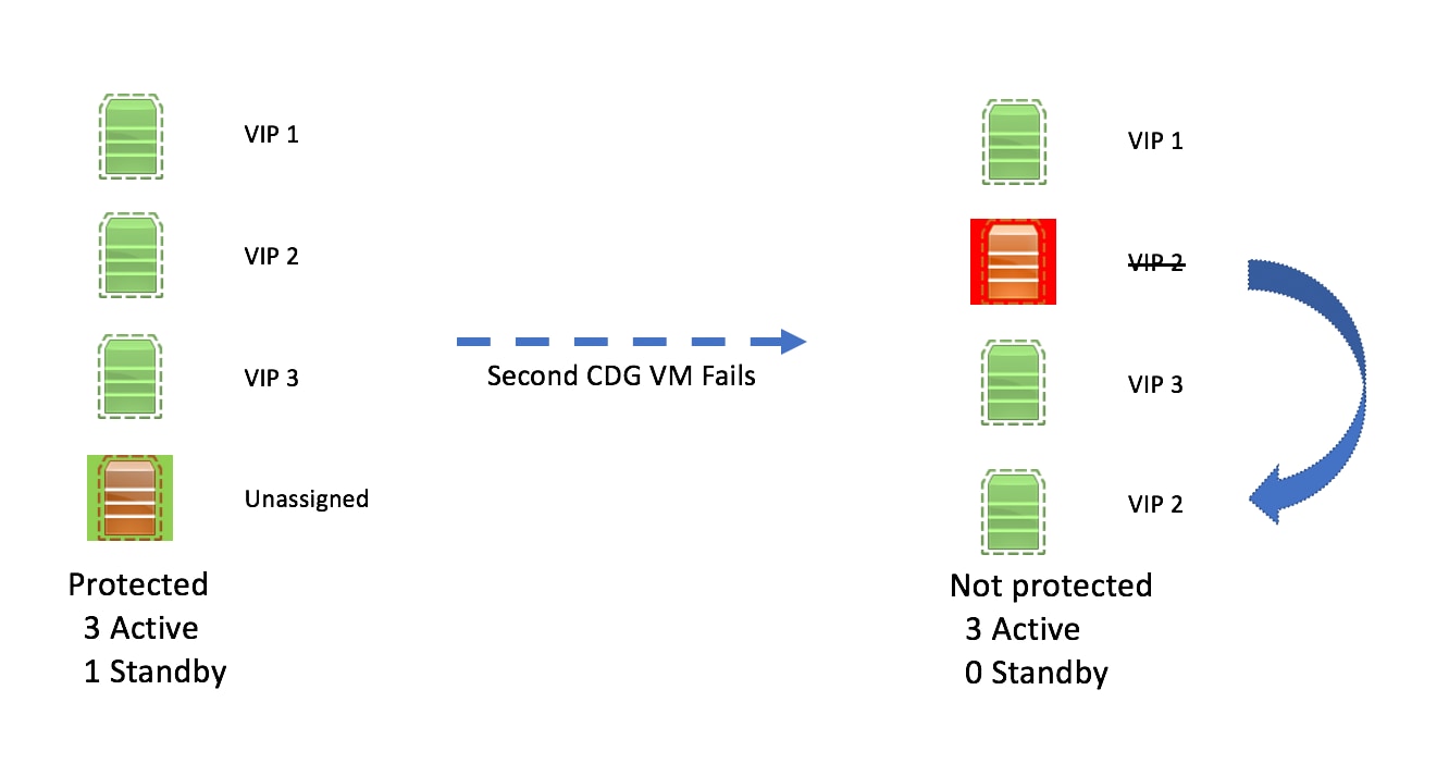
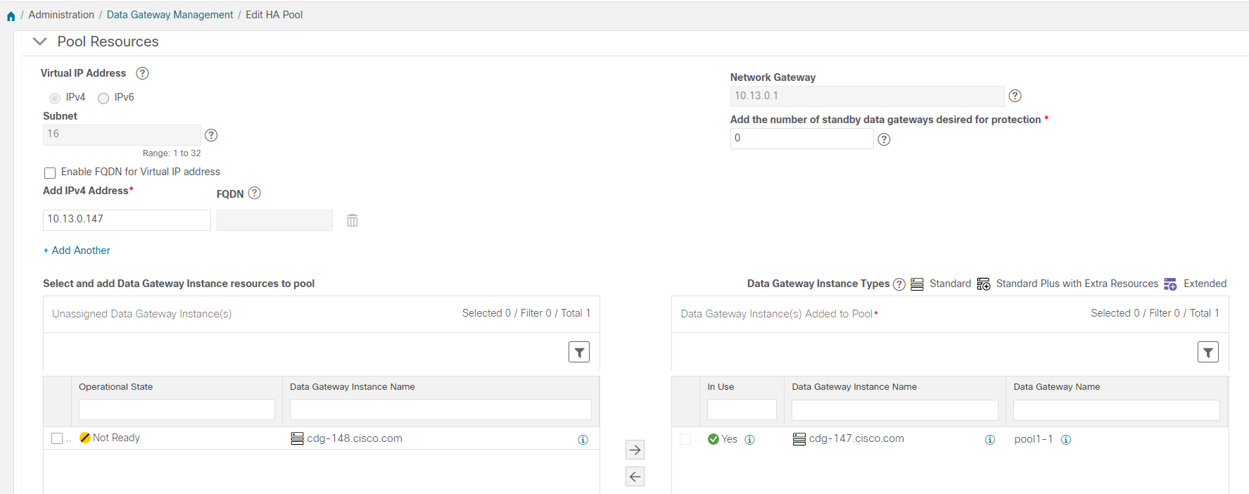
  • Crosswork Data Gateway Pool - A logical unit of one or more Crosswork Data Gateway VMs with an option to enable high availability. When a Crosswork Data Gateway VM goes down, Cisco Crosswork automatically replaces the VM with a spare VM from the pool to ensure that devices are managed and data collections have minimal disruption.

  • Crosswork Data Gateway- A Crosswork Data Gateway VM that is assigned a virtual IP address when it is added to a Crosswork Data Gateway pool. Operations such as attaching or detaching devices, creating collection jobs happen on the Crosswork Data Gateway.

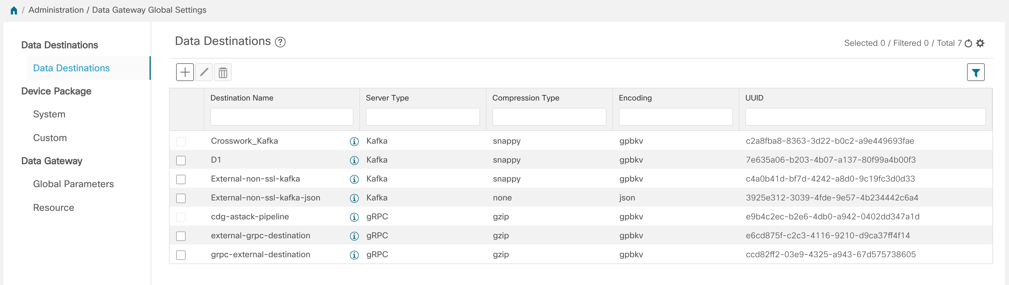
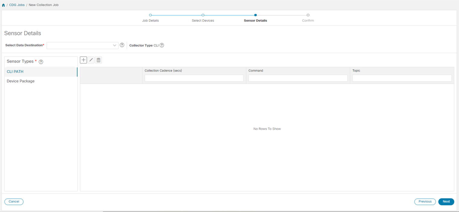
  • Data Destination - Internal or external recipients of data collected by the Crosswork Data Gateway. By default, Cisco Crosswork is defined as a data destination. Other destinations (external users) can be defined using the Cisco Crosswork UI or APIs.

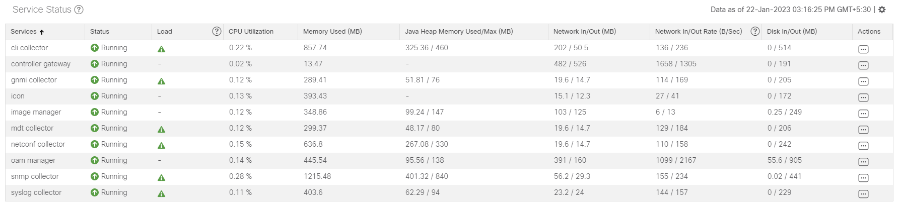
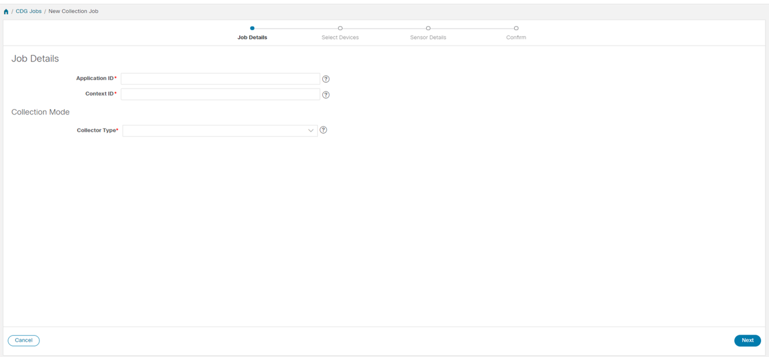
  • Collection Job - A task that Crosswork Data Gateway has to complete to collect data. Crosswork applications create collection jobs to check device reachability, collect telemetry data needed to determine network and service health. The Cisco Crosswork UI and API allow you to configure collection jobs for non-Crosswork applications.

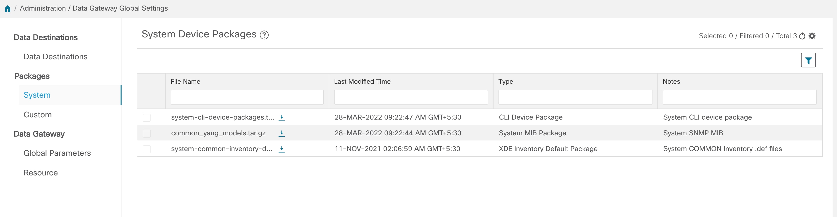
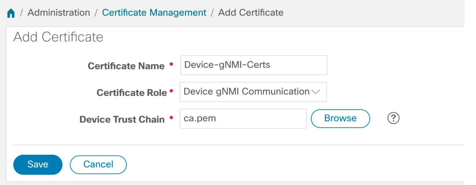
  • Custom Software Packages - Files and device model definitions to extend device coverage and support data collection from currently unsupported devices.


Note

This chapter explains only the Cisco Crosswork Data Gateway features that can be accessed via Cisco Crosswork UI. For more information about Cisco Crosswork Data Gateway Base VM and how to manage it, see Appendix A: Configure Crosswork Data Gateway VM.


Crosswork Data Gateway UI Overview

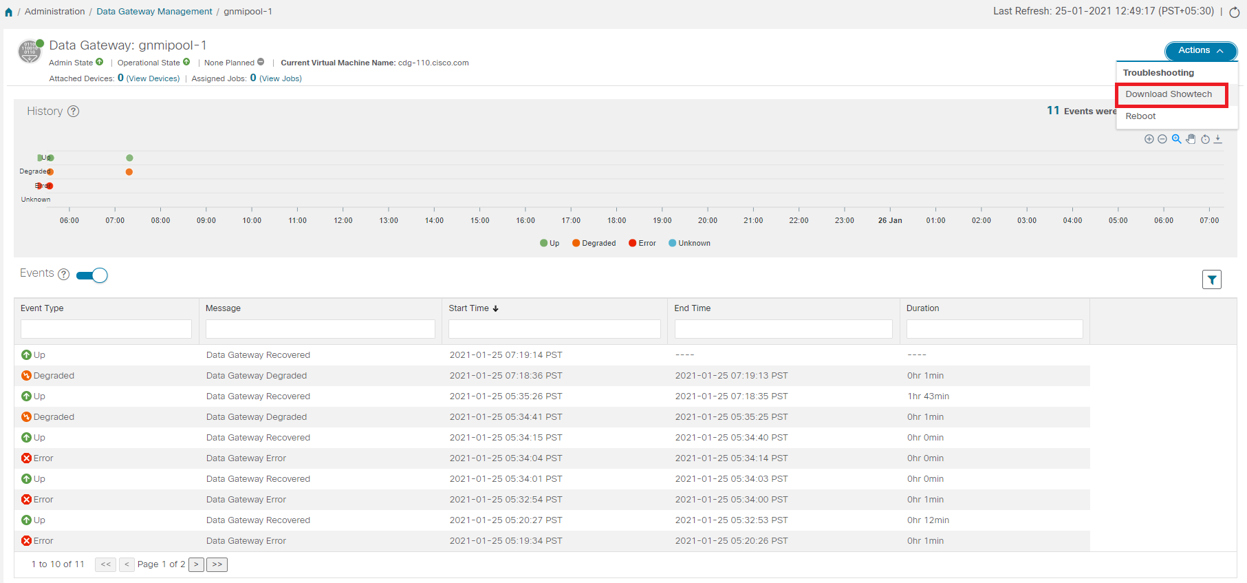
To open the Cisco Crosswork Data Gateway management view, log in to Cisco Crosswork and choose Administration > Data Gateway Management from the left navigation bar.

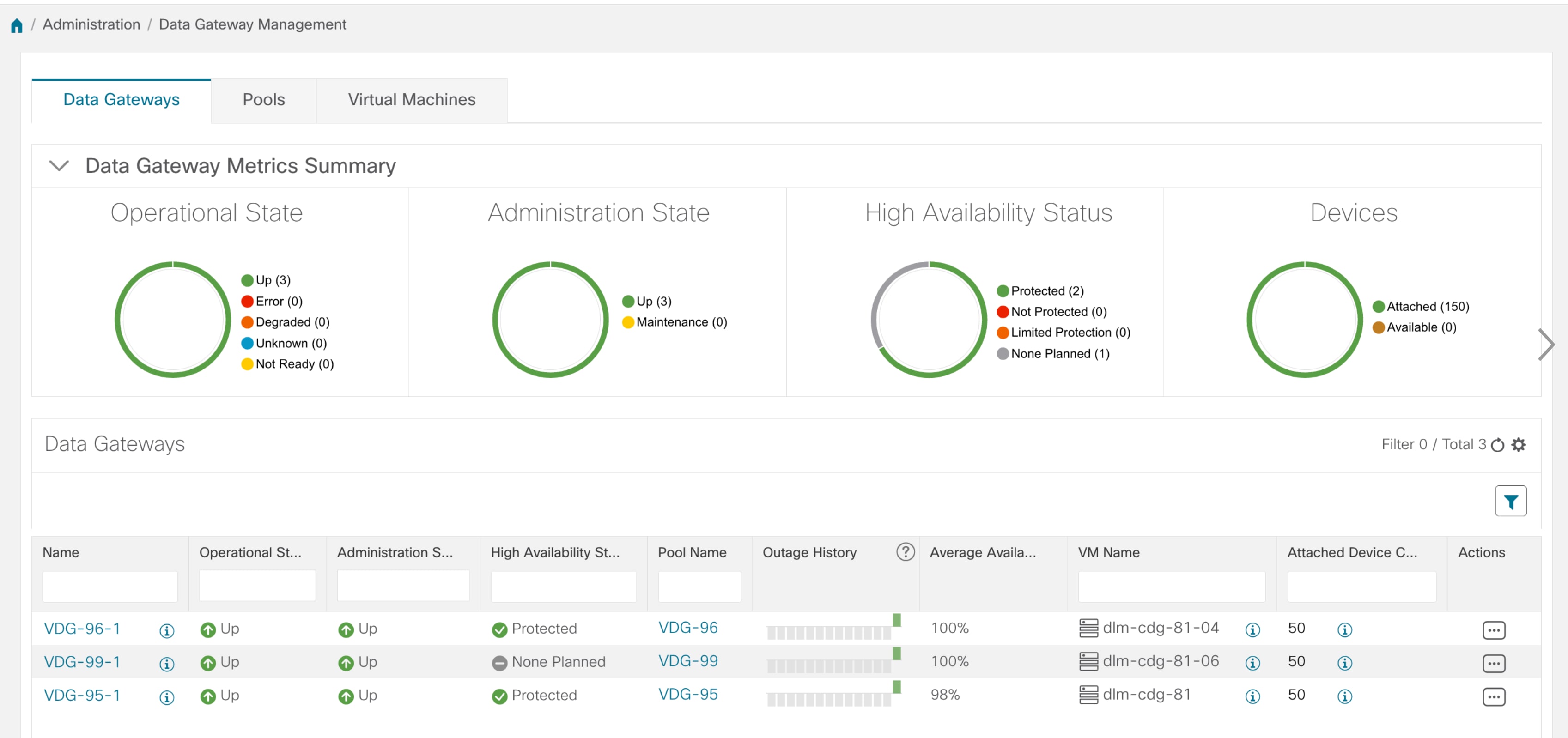
The Data Gateway Management page has three tabs:

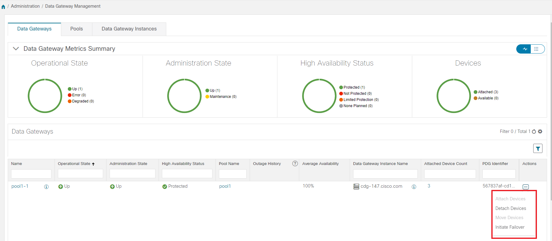
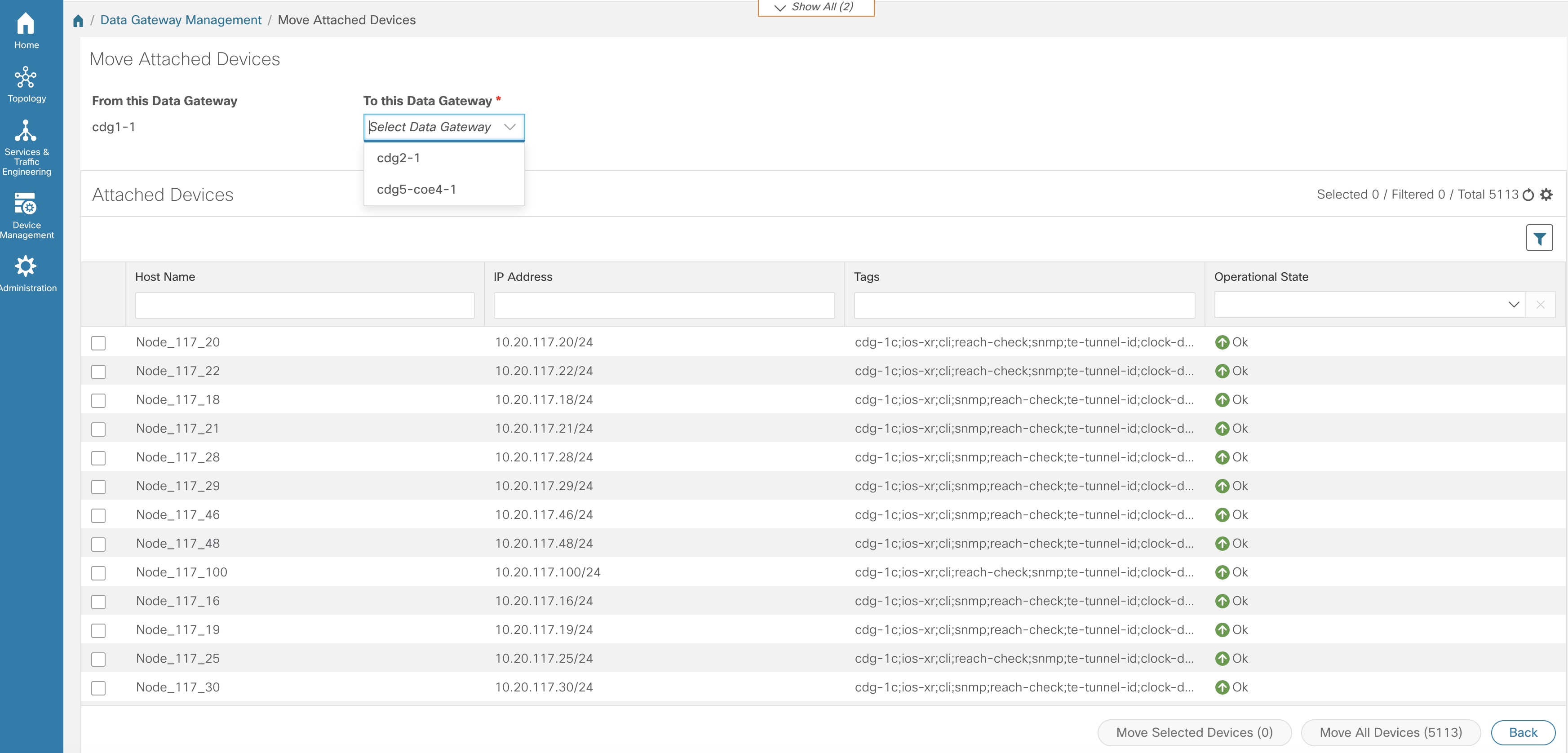
  • Data Gateways: Displays details of the virtual Cisco Crosswork Data Gateways in the network. You can attach or detach devices to the Data Gateway from this tab.

  • Pools: Manage Cisco Crosswork Data Gateway pools.

  • Virtual Machines: Manage physical Cisco Crosswork Data Gateway VMs.

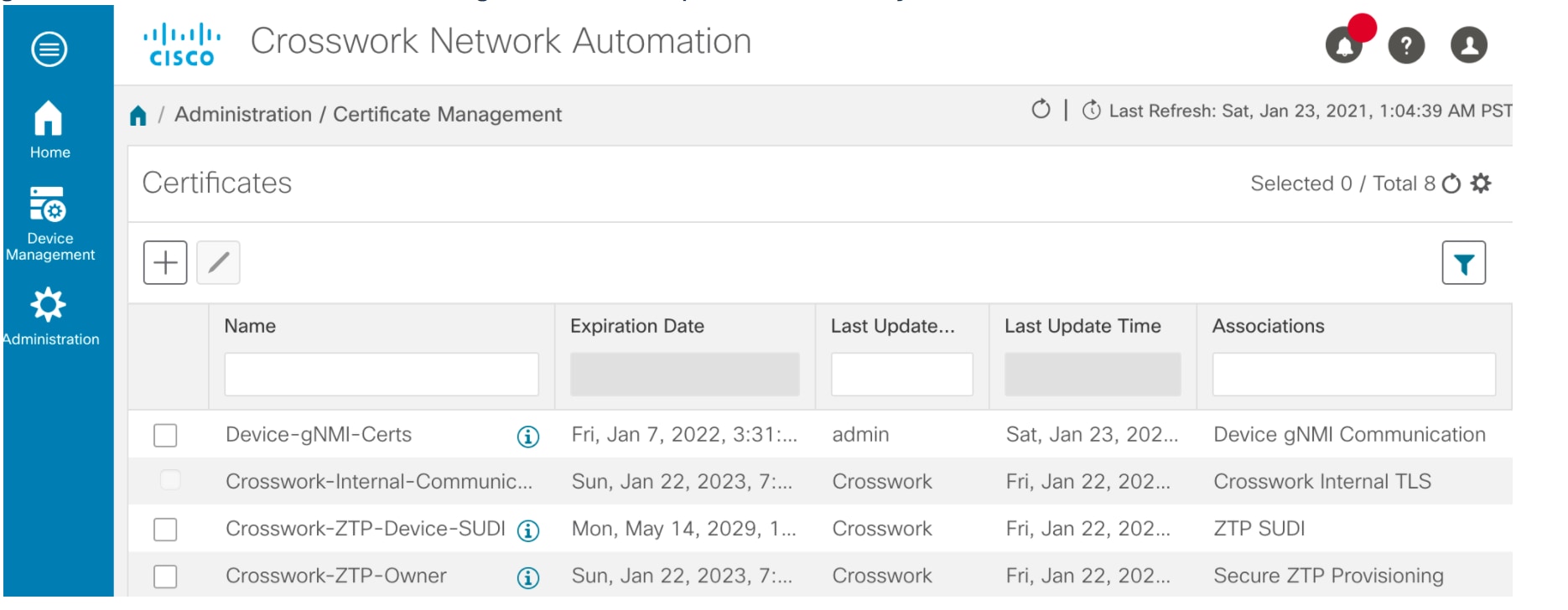
The following table explains the various fields in the Data Gateway Management page.

Table 1. Cisco Crosswork Data Gateway UI

Field

Description

Operational State

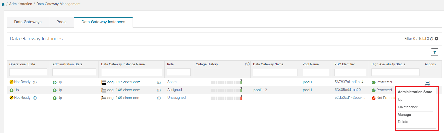
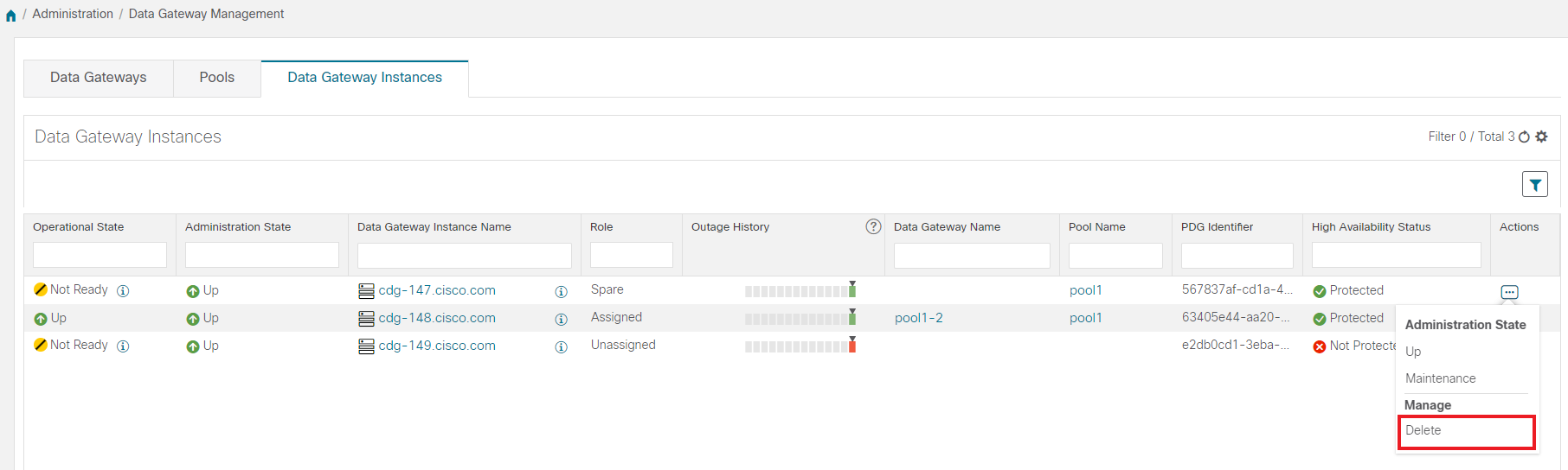
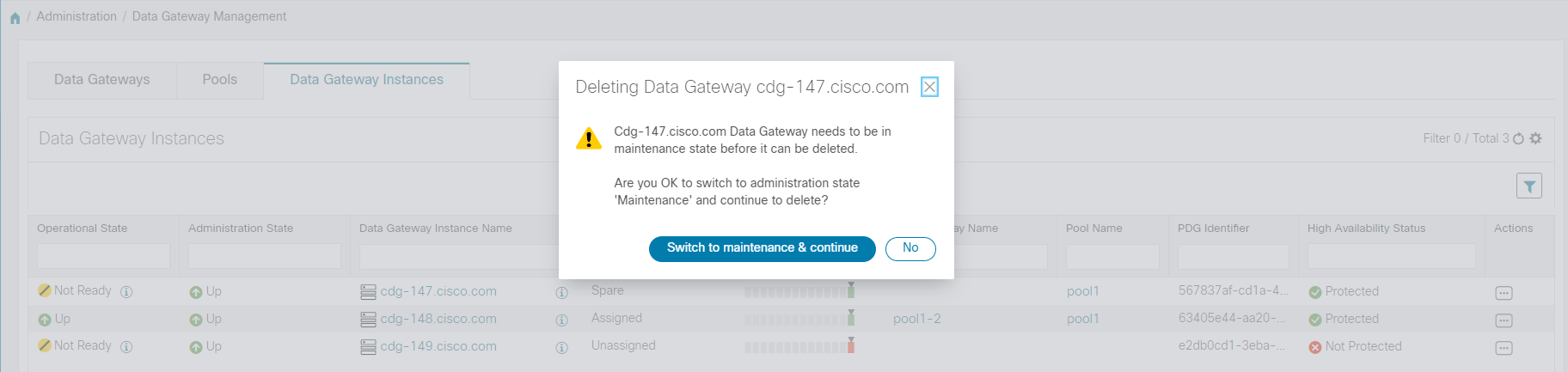
Operational state of the Cisco Crosswork Data Gateway VM.

A Crosswork Data Gateway VM has following operational states:

  • Reachability Unknown icon Unknown:

    The Crosswork Data Gateway VM's operational state is unknown as it has enrolled itself with Cisco Crosswork, but hasn't established a session yet.

  • Degraded icon Degraded:

    The Cisco Crosswork Data Gateway VM is reachable but one or more of its components are in a state other than OK.

  • Not Ready: When Cisco Crosswork Data Gateway has enrolled with Cisco Crosswork but is not ready to receive collection jobs since it is not an Active Data Gateway with an associated south bound virtual IP address

  • Up icon Up: The Cisco Crosswork Data Gateway VM is operational and all individual components are "OK".

  • Error icon Error:

    The Cisco Crosswork Data Gateway VM is unreachable or some of its components are in Error state.

Admin State

Administration state of the Cisco Crosswork Data Gateway VM.

  • Up iconUp: The VM is administratively up.

  • Maintenance Mode icon Maintenance: Operations between Cisco Crosswork and the Cisco Crosswork Data Gateway are suspended to perform upgrades or other maintenance activities (for example, uploading certificates).

Virtual Machine Name

Name of the Cisco Crosswork Data Gateway VM.

Clicking the info icon next to the name displays the enrollment details of each VM. This includes details such as, the

  • Pool name

  • VM name

  • VM Type indicating if the profile of the Crosswork Data Gateway is Standard, Extended or Standard-Plus (the VM resource profile choosen during installtion is On-Premise Standard with Extra Resources).

  • Management IP (eth0) with related MAC address

  • eth1 IP (north bound/vNIC1) with related MAC address

  • eth2 (south bound/vNIC2) with only the MAC address

    Note 

    The eth2 IP (south bound IP) is assigned to the Crosswork Data Gateway VM during pool creation. Hence, it will not be displayed as part of enrollment details for each VM.

IPv4 Mgmt.IP Address

Management IPv4 address of the Cisco Crosswork Data Gateway VM.

IPv6 Mgmt.IP Address

Management IPv6 address of the Cisco Crosswork Data Gateway VM.

Role

Shows the role of the Cisco Crosswork Data Gateway VM. It can be either:

  • Assigned: when Cisco Crosswork Data Gateway VM is assigned to a pool.

  • Unassigned: when Cisco Crosswork Data Gateway VM is not assigned to any pool.

  • Spare: when Cisco Crosswork Data Gateway VM is part of a pool but is in standby mode

Cisco Crosswork Data Gateway VMs that have the Role as Unassigned need to be assigned to a Crosswork Data Gateway pool before they can used.
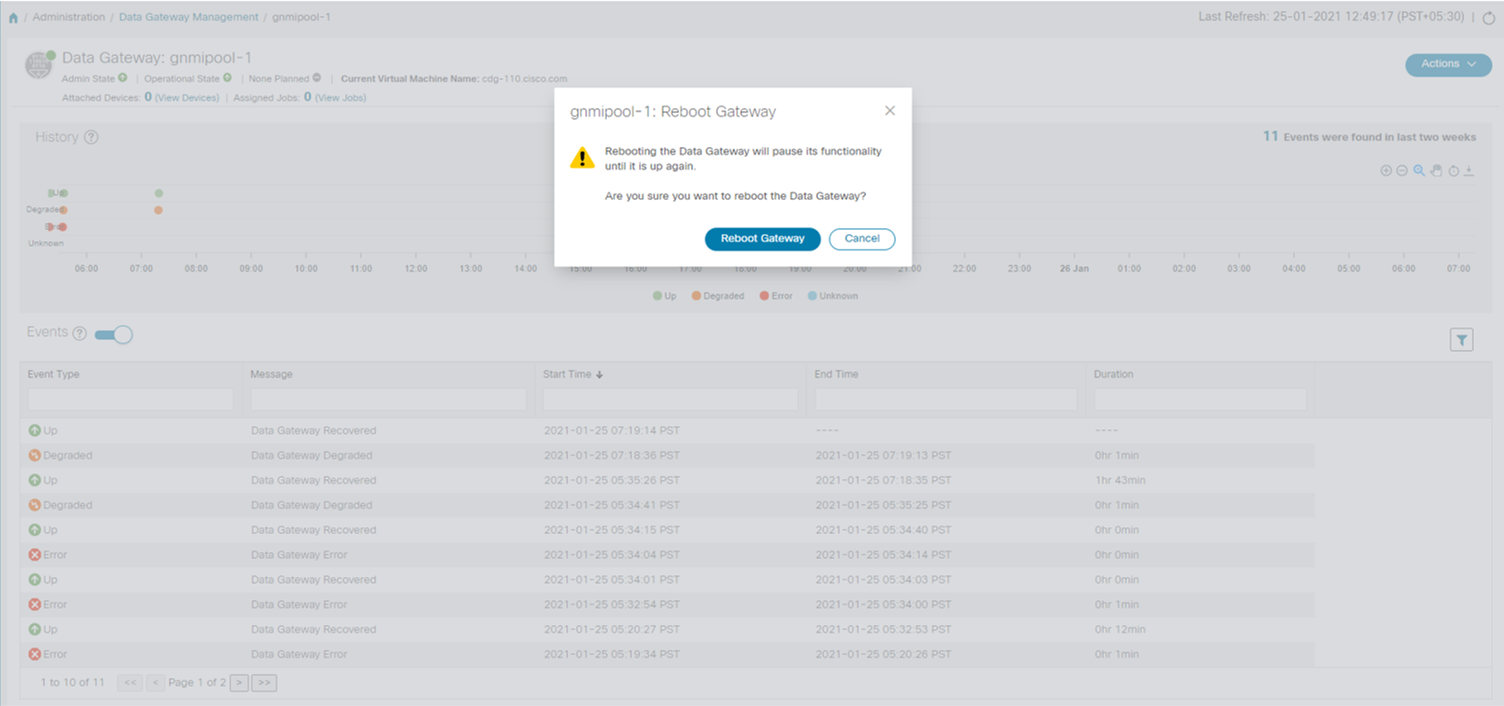
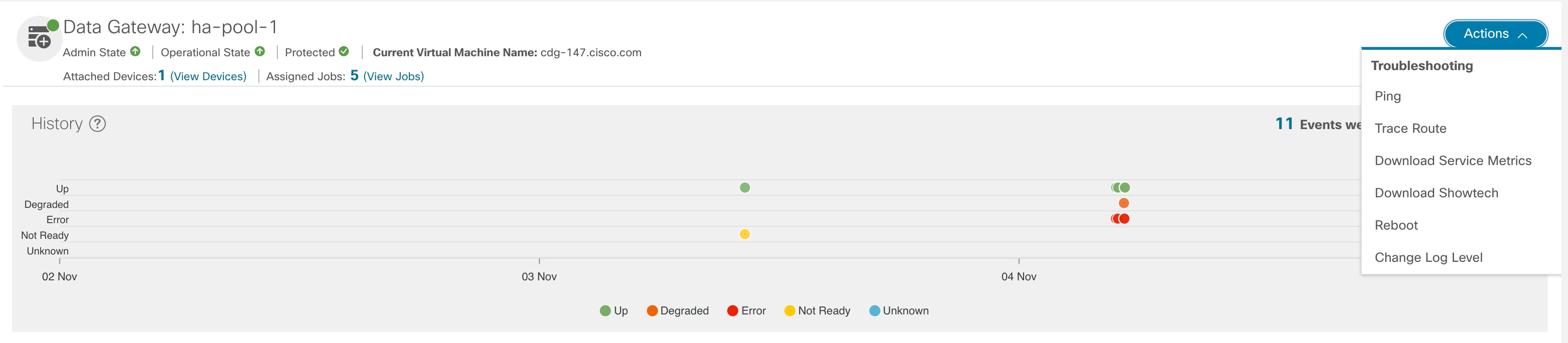
Outage History

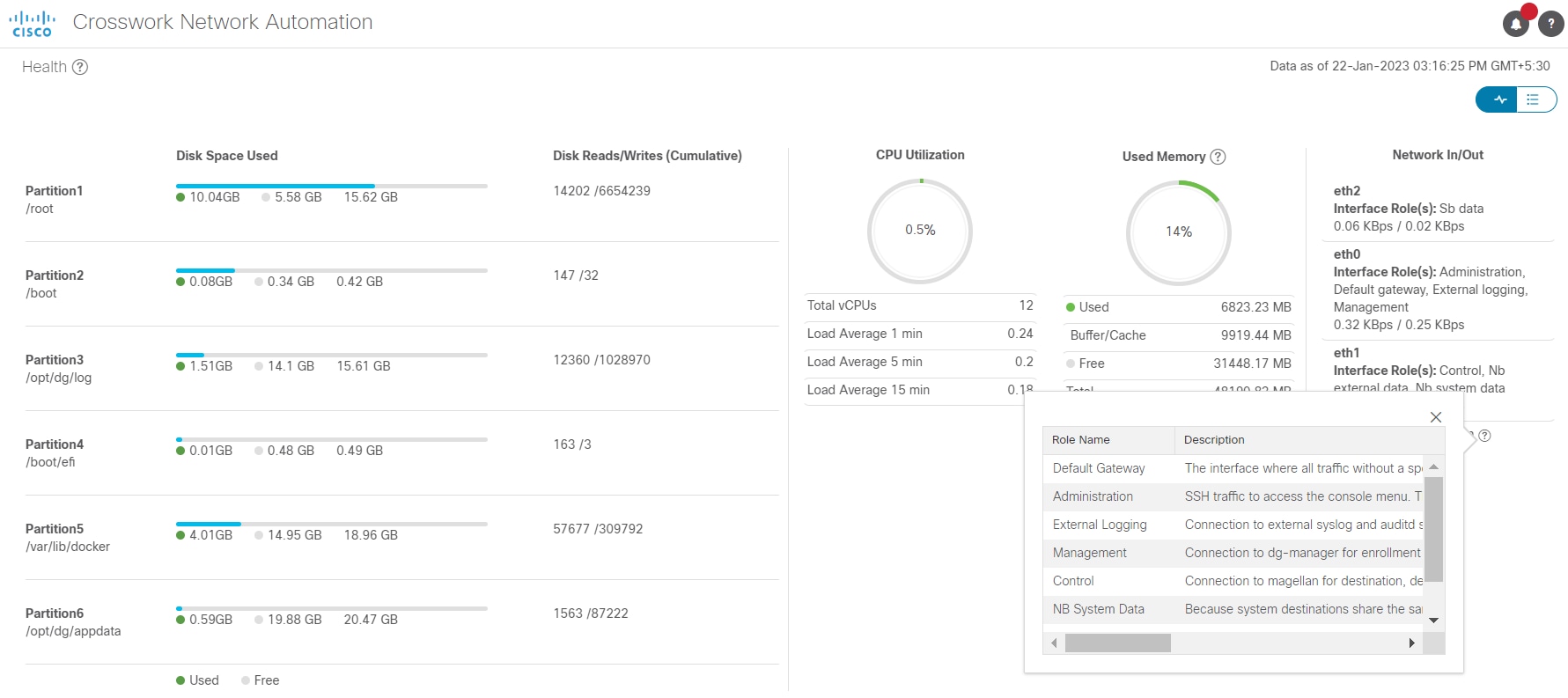
Outage history of the Cisco Crosswork Data Gateway VM over a period of 14 days.

State aggregation for a day is done in the order of precedence as Error , Degraded, Up, Unknown and Not Ready.

For example, if the Crosswork Data Gateway VM went Unknown to Degraded to Up, color is displayed as Degraded (orange) for that day as Degraded takes precedence over Up and Unknown.

If the Crosswork Data Gateway was in Error state at any time during that day, the tile is Red. If the Data Gateway was not in Error but in Degraded State anytime of the day, the tile is Orange. If the DG was not in Error or Degraded state and was only Up, then the tile is Green.

Pool Name

Name of the Crosswork Data Gateway pools to which the Crosswork Data Gateway VM has been assigned.

Data Gateway Name

Name of the Cisco Crosswork Data Gateway that is created automatically when you add a Crosswork Data Gateway VM to a pool.

High Availability Status

High availability status of a Crosswork Data Gateway could be either:

  • Protected: All VMs are UP and there is at least one standby available in the pool.

  • Not Protected: All standby VMs are DOWN.

  • Limited Protection: Some standby VMs are DOWN, but there is still at least one standby that is UP.

  • None Planned: No standby VMs were added to the pool during pool creation.

Average Availability

Value indicating the health of the Cisco Crosswork Data Gateway VM. This percentage is calculated as the total time (in milliseconds) a Crosswork Data Gateway was in UP state over the time between start time of first event and end time of last event .

Note 
The end time of last event is the current time stamp, so the duration of last event is between its start time and current time stamp.

VM ID

VM ID of the Cisco Crosswork Data Gateway VM.

Attached Device Count

Number of devices attached to the Cisco Crosswork Data Gateway pool.

Unique Identifier

Unique identifier of the Cisco Crosswork Data Gateway VM.

Set Up Crosswork Data Gateway to Collect Data

Crosswork Data Gateway requires you to complete the following setup tasks first, before it can run collection jobs.


Note

This workflow assumes that you have already installed Cisco Crosswork Data Gateway as explained in Cisco Crosswork Infrastructure 4.1 and Applications Installation Guide.


It is sufficient to complete Step 1 to Step 3 in the following table to get Crosswork Data Gateway set up and running with Cisco Crosswork and other Crosswork applications. Step 4 to Step 6 are optional and required only in case you wish to extend the Crosswork Data Gateway's capability to collect and forward data by creating external data destinations and custom collection jobs.

Table 2. Tasks to Complete to Set Up Cisco Crosswork Data Gateway to Collect Data

Task

Follow the steps in...

1. Create Crosswork Data Gateway pools.

Create a Cisco Crosswork Data Gateway Pool

2. Attach devices to Crosswork Data Gateway.

Attach Devices to a Crosswork Data Gateway

3. Verify that the default collection jobs are created and running successfully.

Monitor Collection Jobs

4. (optional) Extend device coverage to collect data from currently unsupported devices or third-party devices.

Manage Custom Device Packages

5. (optional) Forward data to external data destinations.

Create and Manage External Data Destinations

6. (optional) Create custom collection jobs (outside of those built for you by Cisco Crosswork).

Manage Crosswork Data Gateway Collection Jobs

Crosswork Data Gateway High Availability with Pools

A Cisco Crosswork Data Gateway pool ensures that your devices are managed and collections occur with minimal disruption.

A pool can consist of one or more Cisco Crosswork Data Gateway VMs with an option to enable high availability.

If a Crosswork Data Gateway VM in the pool goes down, Cisco Crosswork automatically replaces that VM with a standby VM from the pool (failover). A Crosswork Data Gateway VM that has the Operational state as Error and is part of a pool that is Protected is eligible for failover. Devices and any existing collection jobs are assigned automatically from the failed VM to the standby VM. Once the VM that went down becomes operational, it becomes a standby VM in the pool.

Figure 1. Crosswork Data Gateway High Availability

Note

If more than one Crosswork Data Gateway VM in a pool have same Southbound IP address, reboot the standby Crosswork Data Gateway, so that the standby Crosswork Data Gateway VM loses its southbound IP address once it comes up.

For example, CDG1 (Active) with southbound IP address IP1 goes down. Cisco Crosswork replaces CDG1 with CDG2(Standby) as new active and programs the same IP1 as southbound IP on CDG2. CDG1 later comes up and becomes the new standby in the pool, but retains the same IP1 as its southbound IP address. This results in both CDG1 and CDG2 having same IP1 as southbound IPs.


A Crosswork Data Gateway pool has following states:

  • Protected: All VMs are UP and there is at least one standby VM in the pool.

  • Not Protected: All the standby VMs are DOWN and there are none available to replace a VM that is in use.

  • Limited Protection: Some standby VMs are DOWN, but there is still at least one standby that is UP.

  • None Planned: No standby VMs were added to the pool during pool creation.

The Operational state of the Data Gateway is considered to be in the Error state if the Datagateway has failed to report its health for 3 consecutive vitals cycles (30 seconds). This failure in reporting health may be due to:

  • Issues in the Datagateway VM. For example, the Data Gateway has run out of resources to report the health.

  • Network issues between Cisco Crosswork and Crosswork Data Gateway.

The Operational state of the Crosswork Data Gateway is checked every 20 seconds. If the active VM is in the Error state , a failover is triggered and the spare VM in the pool becomes the active VM in the pool.

Enable FQDN for Secure Syslog Communication

Crosswork Data Gateway supports secure syslog communication to devices which require the syslog certificate to contain the host name or Fully Qualified Domain Name (FQDN) instead of the virtual IP address of the Crosswork Data Gateway. This is an optional feature that can be enabled for devices which mandate having the host name or FQDN in the syslog certificate. If enabled, Cisco Crosswork fetches the host name or FQDN for each virtual IP address of the Crosswork Data Gateway from the DNS server. FQDNs for newly added virtual IP(s) will be fetched after you save the pool. The syslog certificate will then contain the FQDN in the CN and SAN instead of the virtual IP address of the Crosswork Data Gateway. For details on how to configure secure syslog on devices, see Configure Secure Syslog on Device.


Note

Crosswork Data Gateway pools can be created without enabling FQDN in which case the syslog certificate will contain virtual IP addresses of the Crosswork Data Gateway. You can always edit the pool later to enable or disable FQDN to switch between having FQDNs or virtual IP addresses in the syslog certificate.


To refresh the FQDN values for virtual IP(s) in the pool (if FQDN values were updated in the DNS server) , use the Actions > Refresh FQDN option for the pool.

Create a Cisco Crosswork Data Gateway Pool

When you create a Cisco Crosswork Data Gateway pool, follow these guidelines:

  • You must create at least one pool and assign Crosswork Data Gateway VMs to it. This step is mandatory to set up the Crosswork Data Gateway for collection.

  • All the Crosswork Data Gateway VMs in a pool need to be of the same configuration (either Standard, Standard Plus or Extended).

To create a Crosswork Data Gateway pool:

Before you begin

Before creating a Cisco Crosswork Data Gateway pool:

  • Decide if you wish to enable high availability for the pool.

  • Ensure that you have installed all Crosswork Data Gateway VMs that you wish to add to the pool.

  • Confirm that the Operational State of the Crosswork Data Gateway VMs is Not Ready.

  • Have network information such as virtual IP address (one virtual IP for each active data gateway), subnet mask and gateway information ready.


    Note

    Gateway is only required when using 3 NICs.

    Depending on the number of number of vNICs in your deployment, the virtual IP address would be:

    • An additional IP address on the Management Network in a single NIC deployment.

    • An additional IP address on the Data Network for 2 NIC deployment.

    • An IP address on the Southbound Network for 3 NICs deployment.

    These virtual IP addresses must be planned in advance during the network design phase.

  • Decide if you wish to enable Fully Qualified Domain Name (FQDN) for virtual IP(s) addresses in the pool. If yes, ensure that you have configured FQDN for virtual IP(s) in the DNS server to create the pool successfully.

Procedure

Step 1

From the main menu, choose Administration > Data Gateway Management and click Pools tab.

Step 2

In the Pools tab, click Add icon button to create a pool.

Step 3

In the Pool Parameters pane, enter the values for the following parameters:

  • Pool Name: Name of the pool that suitably describes the network.

  • Description: A description of the pool.

Step 4

In the Pool Resources pane, add the following details:

  • IPv4 or IPv6: Select either an IPv4 or IPv6 address family for virtual IPs.

  • Subnet Mask: Subnet mask for each Cisco Crosswork Data Gateway

  • Gateway: Gateway address for each Cisco Crosswork Data Gateway to communicate with the devices.

    Note 
    This field is not applicable if a Cisco Crosswork Data Gateway VM has fewer than 3 vNICs.
  • (Optional) Enable FQDN for Virtual IP address: Select this option to use hostname or Fully Qualified Domain Name (FQDN) for each virtual IP address of the Crosswork Data Gateway in the syslog certificate.

  • Add IPv4 or Add IPv6: Based on the address family you chose earlier (IPv4 or IPv6), enter a virtual IP address for every active Cisco Crosswork Data Gateway VM.

  • Add the number of standby data gateways desired for protection: Entering a value greater than 0 in this field enables high availability for the pool. When an active data gateway goes down, a 'standby' in the pool replaces it to ensure protection.

    The number of Crosswork Data Gateway VMs you add to the pool should be equal to the total number of virtual IPs and standby Crosswork Data Gateway VMs. For example, if you have entered 3 virtual IPs and wish to have 2 standby VMs, add 5 Cisco Crosswork Data Gateway VMs to the pool.

  • Select and Add VM Resources to pool: Select VMs from the Unassigned Virtual Machine(s) on the left and click right arrow to move the VMs to the Virtual Machine(s) Added to Pool.

Step 5

Click Save.


After you click Save, a virtual Crosswork Data Gateway gets created automatically and is visible under Data Gateways tab. Attach devices to this virtual Crosswork Data Gateway to run collection jobs.

Note

Pool creation will fail if the FQDN configurations are missing for virtual IP(s) in the DNS server. Either check FQDN configuration in the DNS server or disable the FQDN option and try again.

Attach Devices to a Crosswork Data Gateway

Follow these guidelines when you attach devices to a Crosswork Data Gateway.

  • A device can be attached to only one Crosswork Data Gateway.

  • For optimal performance, we recommend attaching devices to a Crosswork Data Gateway in batches of 300 devices or fewer.

Before you begin

Ensure that the Admin state and Operational state of the Crosswork Data Gateway to which you want to attach devices is Up.

Procedure


Step 1

(Optional) Before attaching devices to an exisiting Crosswork Data Gateway, we recommend that you check the health of the Crosswork Data Gateway. See Monitor Crosswork Data Gateway Health for more information.

Step 2

From the main menu, navigate to Administration > Data Gateway Management > Data Gateways.

Step 3

For the Crosswork Data Gateway to which you want to attach devices, in Actions column, click Edit icon and select Attach Devices. The Attach Devices window opens showing all the devices available for attaching.

Step 4

To attach all the devices, click Attach All Devices. Otherwise, select the devices you want to attach and click Attach Selected Devices.

Step 5

In Confirm - Attach Devices dialog, click Attach.


Verify that your changes are successful by checking the Attached Device Count column in the Data Gateways pane.

Monitor the Crosswork Data Gateway health to ensure that the Crosswork Data Gateway is functioning well with the newly attached devices. See Monitor Crosswork Data Gateway Health.

Manage Crosswork Data Gateway Post-Setup

This section explains various maintenance tasks within the Crosswork Data Gateway.

Monitor Crosswork Data Gateway Health

You can view the operations and health summary of a Crosswork Data Gateway from the Crosswork Data Gateway details page at Administration > Data Gateway Management > Data Gateways > (click){Crosswork Data Gateway}. This page also has details of the health of various containerized services running on the Crosswork Data Gateway. The overall health of Crosswork Data Gateway also depends on the health of each containerized service.

The following parameters are displayed in this page.

  • General Cisco Crosswork Data Gateway Details - Displays general details of the Crosswork Data Gateway including operational state, high availability state, attached device count, and assigned jobs. The Actions option lists the various troubleshooting options that are available from the UI.

  • History - Shows the outage history chart of the Cisco Crosswork Data Gateway over 14 days including timestamp, outage time, and clear time. Use the options in the top-right corner of the pane to zoom in, zoom out, pan, or download the SVG and PNG of the history chart of a specific time period within the graph.

  • Events - Displays a list of all Cisco Crosswork Data Gateway transition state changes over the last 14 days. It includes information such as the event details, including operational state changes, role changes, a message indicating the reason for the status change, timestamp, and duration.

  • Health - Shows the health information of the Cisco Crosswork Data Gateway. The timestamp in the top-right corner is the timestamp when the last health data was collected. If the Crosswork Data Gateway is in an Error state or if the data is stale for any reason, the timestamp label highlights that the data is old. If the CPU Utilization of a Crosswork Data Gateway exceeds 80%, we recommend taking corrective action before the CPU Utilization increases further leading to failure of the Crosswork Data Gateway.

  • Service Status - Displays the health information of the individual container services running on the Crosswork Data Gateway and their resource consumption with an option to restart (Action> Restart) an individual service. The Load column indicates the processing load of that specific collector/service. The load score of a collector is calculated using several metrics. . The load scores are mapped to low, medium or high severity zones. A collector that is consistently operating in the High zone will mean that the collector has reached peak capacity for the given CPU/Memory resource profile. For more information on how the load score is calculated, see Load Score Calculation


    Note

    The list of container services differs between Standard Crosswork Data Gateway and Extended Crosswork Data Gateway. Extended Crosswork Data Gateway has more containers installed.

    The resource consumption data that is displayed is from docker statistics. These values are higher than the actual resources consumed by the containerized service.


We recommend monitoring the health of the Crosswork Data Gateways in your network periodically to prevent overloading and take corrective actions, such as adding additional resources or reducing load on the Crosswork Data Gateway well in time proactively.

  1. Alarms are generated by the DG-Manager if the Crosswork Data Gateway fails or is getting close to reaching resource capacity limits.

  2. If the CPU Utilization of a Crosswork Data Gateway exceeds 80%, we recommend that you do not create more collection jobs until you have reduced the CPU Utilization by moving devices to another CDG or have added other VMs to the pool or the increased the cadence of existing collection jobs.

  3. If the CPU Utilization of a Crosswork Data Gateway exceeds 90%, we recommend that you move devices to another Crosswork Data Gateway that has a lower CPU Utilization percentage.

  4. We recommend that you check the system alarms weekly. Investigate to confirm it is not because of a resource problem and data drops are not frequent. Then fix issues on the data destinations or increase cadence of the collection job.

Manage a Crosswork Data Gateway Pool

Follow the steps to edit or delete a Cisco Crosswork Data Gateway pool. To create a pool, see Create a Cisco Crosswork Data Gateway Pool.

Before you begin

Important points to consider before you edit or delete the pool:

  • Virtual IP addresses that have devices attached cannot be deleted.

  • A Crosswork Data Gateway VM can be removed from the pool only if all devices have been unmapped from the Crosswork Data Gateway. When a Crosswork Data Gateway VM is removed from the pool, a standby VM from the same pool becomes its replacement automatically.

  • Before you delete a Crosswork Data Gateway pool, detach devices from the Crosswork Data Gateway first or move the devices to another Crosswork Data Gateway.

Procedure


Step 1

From the main menu, choose Administration > Data Gateway Management and click Pools tab.

Step 2

Edit a Crosswork Data Gateway Pool:

  1. Select the pool which you wish to edit from the list of pools that is displayed in this page,

  2. Click Edit icon button to open Edit High Availability (HA) Pool page.

    When you edit a resource pool, you can only change the parameters in the Pool Resources pane. You cannot edit the parameters in the Pool Parameters pane. To make changes to the parameters in the Pool Parameters pane, create a new pool with the desired values and move the Cisco Crosswork Data Gateway VMs to that pool.

  3. In the Pool Resources pane, you can:

    • Add and delete a virtual IP address for every active data gateway needed.

    • Change the number of standby Crosswork Data Gateway VMs.

    • Add and remove Crosswork Data Gateway VMs from the pool.

    • Enable or disable FQDN for the pool.

  4. Click Save after you have completed making your changes.

Step 3

Delete a Crosswork Data Gateway Pool:

  1. Select the pool you want to delete and click Delete icon.

  2. Click Delete in the Delete High Availability (HA) Pool window to delete the pool.


Manage Cisco Crosswork Data Gateway Device Assignments

Follow these guidelines when you move or detach devices from a Crosswork Data Gateway.

  • A device can be attached to only one Crosswork Data Gateway.

  • When moving devices to a Crosswork Data Gateway in different pool, ensure that the Gateway of the pool is same as the Gateway of the current pool. Moving devices to a Crosswork Data Gateway with mismatching Gateway will result in failed collections.

  • Detaching a device from Cisco Crosswork Data Gateway deletes all collection jobs corresponding to the device. If you do not want to lose the collection jobs submitted for the device you wish to detach, move the device to another Cisco Data Gateway instead.

Follow the steps below to move or detach devices from a Crosswork Data Gateway pool. To add devices to the pool, see Attach Devices to a Crosswork Data Gateway.

Procedure


Step 1

From the Cisco Crosswork Main Menu, navigate to Administration > Data Gateway Management > Data Gateways.

Step 2

Move Devices:

  1. For the Crosswork Data Gateway from which you want to move devices, under Actions column, click Edit icon and select Move Devices. The Move Attached Devices window opens showing all the devices available for moving.

  2. From the To this Data Gateway dropdown, select the data gateway to which you want to move the devices.

  3. To move all the devices, click Move All Devices. Otherwise, select the devices you want to move and click Move Selected Devices.

  4. In Confirm - Move Devices window, click Move.

Step 3

Detach Devices:

  1. For the Crosswork Data Gateway from which you want to detach devices, under Actions column, click Edit icon and select Detach Devices. The Detach Devices window opens showing all attached devices.

  2. To detach all the devices, click Detach All Devices. Otherwise, select the devices you want to detach and click Detach

  3. In Confirm - Detach Devices window, click Detach


Verify that your changes are successful by checking the Attached Device Count under the Data Gateways pane. Click the i icon next to the attached device count to see the list of all devices attached to the selected Crosswork Data Gateway.

Maintain Crosswork Data Gateway VMs

This section explains the maintenance tasks of the Crosswork Data Gateway VM.

Change the Administration State of Cisco Crosswork Data Gateway VM

To perform upgrades or other maintenance within the data center is may become necessary to suspend operations between Cisco Crosswork platform and the Cisco Crosswork Data Gateway. This can be done by placing the Cisco Crosswork Data Gateway into Maintenance mode. During downtime, admin can do modifications to Cisco Crosswork Data Gateway, such as updating the certificates, etc.


Note

If the maintenance activities are affecting the communication between Crosswork and Crosswork Data Gateway, the collection is interrupted and resumes when the communication is restored. Similarly if the maintenance activities are affecting the communication between Crosswork Data Gateway and external destinations (Kafka/gRPC), the collection is interrupted and resumes when the communication is restored.


Once changes are done, admin can change the administration state to Up. Once the Crosswork Data Gateway VM is up, Cisco Crosswork resumes sending jobs to it.


Note

Maintenance (work done on the network or network outages) do not stop collections even though they may fail. In case of a Crosswork Data Gateway VM with the Administration state as Maintenance, the collections stop gracefully and resume when the VM returns to having the Administration state as Up.

Follow the steps below to change the administration state of a Crosswork Data Gateway VM:

Procedure

Step 1

From the main menu, choose Administration > Data Gateway Management > Virtual Machines.

Step 2

For the Cisco Crosswork Data Gateway whose adminstrative state you want to change, click on Edit icon under Actions column.


Step 3

Select the adminstration state to which you want to switch to.


Delete Cisco Crosswork Data Gateway VM from Cisco Crosswork

Follow the steps below to delete a Cisco Crosswork Data Gateway VM from Cisco Crosswork:

Before you begin

It is recommended that you move the attached devices to another data gateway to not lose any jobs corresponding to these devices. If you detach the devices from Cisco Crosswork Data Gateway VM, then the corresponding jobs are deleted.

Procedure

Step 1

From the main menu, choose Administration > Data Gateway Management > Virtual Machines.

Step 2

For the Crosswork Data Gateway that you want to delete, click Edit icon under Actions column and click Delete.


Step 3

The Cisco Crosswork Data Gateway VM must be in maintenance mode to be deleted. Click Switch & Continue when prompted to switch to Maintenance mode..


Step 4

Check the check box for "I understand the concern associated with deleting the Data Gateways." and click Remove CDG.


Redeploy a Crosswork Data Gateway VM

If a Crosswork Data Gateway VM has gone down and can no longer be used, then delete the old VM and install a new one. For details on how to install a new Crosswork Data Gateway VM, refer to Section: Install Cisco Crosswork Data Gateway in the Cisco Crosswork Infrastructure 4.1 and Applications Installation Guide.


Note

If the Crosswork Data Gateway VM was already enrolled with Cisco Crosswork and you have installed the VM again with the same name, change the Administration State of the Crosswork Data Gateway VM to Maintenance for auto-enrollment to go through.


If a Crosswork Data Gateway VM was already enrolled with Cisco Crosswork and Cisco Crosswork was installed again, re-enroll the existing Crosswork Data Gateway VM with Cisco Crosswork. See Re-enroll Crosswork Data Gateway.

Configure Crosswork Data Gateway Global Settings

This section describes how to configure global settings for Cisco Crosswork Data Gateway. These settings include:

Create and Manage External Data Destinations

Cisco Crosswork allows you to create external data destinations (Kafka or external gRPC) that can be used by collection jobs to deposit data.

It can be accessed by navigating to Administration > Data Gateway Global Settings > Data Destinations. You can add a new data destination, update the settings configured for an existing data destination, and delete a data destination.

The table in the Data Destinations page lists the approved data destinations that can be used by the collection jobs to deposit their data.


Note

The Crosswork_Kafka and cd-astack-pipeline are internal data destinations and cannot be updated or deleted.


The UUID is the Unique identifier for the data destination. Cisco Crosswork automatically generates this ID when an external data destination is created. When creating collection jobs using the Cisco Crosswork UI the destination for the data is selected using a drop-down list of the configured destinations. When creating a collection job via the API, you will need to know the UUID of the destination where the collector is to send the data it collects.

To view details of a data destination, in the Data Destinations pane, click icon next to the data destination name whose details you want to see.

Licensing Requirements for External Collection Jobs

To be able to create collection jobs that can forward data to external data destinations, ensure that you meet the following licensing requirements:

  1. From the main menu, go to Administration > Application Management > Smart License.

  2. Select Crosswork Platform Services in the application field.

  3. Ensure that the status is as follows:

    • Registration Status - Registered

      Indicates that you have registered with Cisco Smart Software Manager (CSSM) and are authorized to use the reserved licensed features.

    • License Authorization Status - Authorized (In Compliance).

      Indicates that you have not exceeded the device count in the external collection jobs.

    • Under Smart Licensing Usage, CW_EXTERNAL_COLLECT has status as In Compliance.

If you do not register with Cisco Smart Software Manager (CSSM) after the Evaluation period has expired or you have exceeded the device count in external collection jobs (License Authorization Status is Out of Compliance), you will not be able to create external collection jobs. However, you can still view and delete any existing collection jobs.

Add or Edit a Data Destination

Follow the steps below to add a new data destination. You can then use this data destination to forward data to. You can add multiple data destinations.

Few points to note when adding an external data destination are:

  • If you re-install an already existing external Kafka data destination with the same IP address, then the collectors need to be restarted for changes to take effect.

  • You can secure the communication channel between Cisco Crosswork and the specified data destination that is, either Crosswork Kafka or external Kafka. (See Step 6 in this procedure). However, enabling security can impact performance.

  • If your external data destination requires a TLS connection, keep the public certificate ready or if it requires client authentication, keep the client certificate and key files ready. The client key might be password-encrypted which will need to be configured as part of the data destination provisioning. Currently, Crosswork Data Gateway supports IP-based certificates only.

  • Ensure that the certificates are PEM encoded and the key file is in PKCS#8 format when generating them with your Certificate Authority.

  • Ensure that you create the Kafka topics before you submit the job in Cisco Crosswork. Depending on the external Kafka and how topics are managed in that external Kafka, Cisco Crosswork logs may show the following exception if the topic does not exist at the time of dispatching the collected data to that specific external Kafka / topic. This could be because the topic is not created yet or the topic was deleted before the collection job was complete.

    destinationContext: topicmdt4
    org.apache.kafka.common.errors.UnknownTopicOrPartitionException: This server does not host this topic-partition.
  • Check and validate the port connectivity for the data destination. If the port is unreachable in the destination, it will lead to a failed collection.

  • Crosswork Data Gateway allows you to configure custom values in the destination properties for a Kafka destination (see Step 4 in this procedure).


    Note

    This feature is not supported on a gRPC destination.


    Global properties entered in the Destination Details pane are mandatory and will be applied to the Kafka destination by default unless there are custom values specified at the individual collector level. Custom values that you specify for a collector will apply only to that collector.

Before you begin

If you are using an external Kafka server for data collection, ensure the following:

  • You have configured the following properties on the external Kafka server:


    Note

    Refer your Kafka documentation for description and usage of these properties as this explanation is out of scope of this document.


    • num.io.threads = 8

    • num.network.threads = 3

    • message.max.bytes= 30000000

  • You have created Kafka topics that you want to be used for data collection.

Procedure

Step 1

From the main menu, choose Administration > Data Gateway Global Settings > Data Destinations.

Step 2

In the Data Destinations page, click Add icon button. The Add Destination page opens.

If you want to edit an existing destination, click Edit icon button to open Edit Destination page and edit the parameters.

Note 

Updating a data destination causes the Cisco Crosswork Data Gateway using it to re-establish a session with that data destination. Data collection will be paused and resumes once the session is re-established.

Step 3

Enter or modify the values for the following parameters:

Field Value

Destination Name

Enter a descriptive data destination name. The name can contain a maximum of 128 alphanumeric characters, plus underscores ("_") or hyphens ("-"). No other special characters are allowed.

If you have many data destinations, make the name as informative as possible to be able to distinguish later.

Server Type

From the drop down, select the server type of your data destination (Kafka/gRPC).

Encoding

From the drop down, select the encoding (json/gpbkv).

Compression Type

From the drop down, select the compression type:

Compression types supported for Kafka are snappy, gzip, lz4, zstd, and none)

Note 

zstd compression type is supported only for Kafka 2.0 or higher.

Compression types supported for gRPC are snappy, gzip, and deflate.

Maximum Message Size (bytes) (Kafka-only)

Enter the maximum message size in bytes.

  • Default Value: 100000000 bytes/ 30 MB

  • Min: 1000000 bytes/1 MB

  • Max: 100000000 bytes/ 30 MB

Buffer Memory (Kafka only)

Enter the required buffer memory in bytes.

  • Default Value: 52428800 bytes

  • Min: 52428800 bytes

  • Max: 314572800 bytes

Batch Size (bytes) (Kafka-only)

Enter the required batch size in bytes.

  • Default Value: 6400000 bytes/6.4 MB

  • Min: 16384 bytes/ 16.38 KB

  • Max: 6400000 bytes/6.4 MB

Linger (milliseconds) (Kafka-only)

Enter the required linger time in milliseconds.

  • Default Value: 5000 ms

  • Min: 0 ms

  • Max: 5000 ms

For telemetry based collection, it is recommended to use the destination settings of Batch size as 16384 bytes and linger as 500 ms, for optimal results.

Step 4

(Optional) To configure custom values that are different from global properties for a Kafka destination, in the Customize Collector Settings pane,and

  1. Select a Collector.

  2. Enter values for the following fields

    • Custom Buffer Memory

    • Custom Batch Size

      Note 
      The Custom Batch Size cannot exceed the value of the Custom Buffer Memory at run time. In case, you do not provide a value in the Custom Buffer Memory field, the Custom Batch Size will be validated against the value in the Buffer Memory field.
    • Custom Linger

    • Custom Request Timeout

  3. Click + Add Another to repeat this step and add custom settings for another collector.

Note 
Properties entered here for individual collectors will take precedence over the global settings entered in Step 3. If you do not enter values in any field here, the values for the same will be taken from the Global properties entered in Step 3.
Step 5

Select a TCP/IP stack from the Connection Details options. IPv4 and IPv6 are supported.

Step 6

Complete the Connection Details fields as described in the following table. The fields displayed will vary with the connectivity type you chose. The values you enter must match the values configured on the external Kafka or gRPC server.

Connectivity Type Fields

IPv4

Enter the required IPv4 Address/ Subnet Mask, and Port. You can add multiple IPv4 addresses by clicking + Add Another

IPv4 subnet mask ranges from 1 to 32 and port range from 1024 to 65535.

IPv6

Enter the required IPv6 Address/ Subnet Mask, and Port. You can add multiple IPv6 addresses by clicking + Add Another.

IPv6 subnet mask ranges from 1 to 128 and port range from 1024 to 65535.

Step 7

(Optional) To connect securely to the data destination, enable the Enable Secure Communication option under Security Details.

Step 8

Click Save.


What to do next
If you have enabled the Enable Secure Communication option, navigate to the Certificate Management page in the Cisco Crosswork UI (Administration > Certificate Management) and add the relevant certificate for the newly added data destination. This step is mandatory to establish a secure communication to the device. See Manage Certificates for more information.

Note

If you do not add the certificate for the data destination after enabling the Enable Secure Communication option, Cisco Crosswork still connects to the destination in non-secure mode for any collection jobs.


Delete a Data Destination

Follow the steps to delete a data destination:

Before you begin
A data destination can only be deleted if it is not associated with any collection job. We recommend to check in the Collection Jobs view to see if any collection jobs are using the data destination.
Procedure

Step 1

From the main menu, choose Administration > Data Gateway Global Settings > Data Destinations.

Step 2

Select the Data destination(s) you want to delete from the list of destinations that is displayed and click Delete icon button.

Step 3

In Delete Data Destination(s) pop up, click Delete to confirm.


Manage Custom Device Packages

You can upload Custom Device Packages to Cisco Crosswork, for example, when required to extend device coverage and collection capabilities to third-party devices. System Device and MIB Packages are bundled in the Crosswork software and are automatically downloaded to the system instances. You cannot modify system device and MIB packages.

You can upload three types of custom device packages to Cisco Crosswork:

  1. CLI Device Package: To use CLI-based KPIs to monitor device health for third-party devices. All custom CLI device packages along with their corresponding YANG models should be included in file custom-cli-device-packages.tar.xz. Multiple files are not supported.

  2. Custom MIB Packages: Custom MIBs and device packages can be specific to third-party devices or be used to filter the collected data or format it differently for Cisco devices. These packages can be edited. All custom SNMP MIB packages along with YANG models should be included in file custom-mib-packages.tar.xz. Multiple files are not supported.


    Note

    Cisco Crosswork Data Gateway enables SNMP polling on third party devices for standard MIBs already included in the system. Proprietary MIBs are required only if the collection request references MIB TABLE names or SCALAR names from a proprietary MIB. However, if the requests are OID-based, then MIBs are not required.


  3. SNMP Device Package: Cisco Crosswork Data Gateway allows you to extend the SNMP coverage by uploading custom SNMP device packages with any additional MIB and YANG descriptions you require.

Device Packages pane can be accessed via Adminstration > Data Gateway Global Settings > Device Packages.

To download a device package, click on the Download icon button next to its name in the File Name column.

Add a Custom Device Package

This is a list of guidelines about uploading device packages to Cisco Crosswork.

  1. You can upload one or more xar file in a single device package tar.gz file.

  2. Cisco Crosswork doesn't allow Custom MIB package files to overwrite the System MIB Package files. It results in a failed upload attempt.

  3. Ensure that the custom device package TAR file has just the device package folders and none of the parent folder or hierarchy of folders as part of the TAR file. If not imported properly, Cisco Crosswork throws exceptions when executing the job with custom device package.

  4. Cisco Crosswork does not validate the files being uploaded other than checking the file extension.

Follow these steps to upload a custom software package:

Before you begin

When uploading new MIBs as a part of Custom MIB Package, ensure that those new MIBs files can be uploaded within collectors along with existing System MIB files i.e., all dependencies in the files are resolved properly.


Note

Performance of collection jobs executing the custom device packages depends on how optimized the custom device packages are. Ensure that you validate that the device package are optimized for the scale you want to deploy them for before uploading to Cisco Crosswork.

For information on how to validate custom MIBs and Yangs i.e., to check if they can be uploaded to Cisco Crosswork, see Use Custom MIBs and Yangs on Cisco DevNet.

Procedure

Step 1

From the main menu, choose Administration > Data Gateway Global Settings.

Step 2

In Custom Device Packages pane, click Add icon.

To update the existing Custom CLI Device Package, click the upload icon next to the File name in the table.

Step 3

In the Add Device Package window that appears, select the type of custom device package you want to import from the Type drop-down.

Step 4

Click in the blank field of File Name to open the file browser window and select the device package to import and click Open.

Step 5

Add a description of the custom device package in the Notes field. This is recommended if you have many packages, to be able to distinguish among them.

Step 6

Click Upload.


What to do next
Restart all impacted services to get the latest custom MIB package updates.

Delete a Custom Device Package

Deleting a custom device package causes deletion of all YANG and XAR files from Cisco Crosswork. This impacts all collection jobs using the custom device package.

Follow the steps to delete a custom device package:

Procedure

Step 1

From the main menu, choose Administration > Data Gateway Global Settings > Device Packages > Custom.

Step 2

From the list displayed in the Custom Device Packages pane, select the custom device package you want to delete and click Delete icon.

Step 3

In the Delete Custom Device Package window that appears, click Delete to confirm.


Configure Crosswork Data Gateway Global Parameters

Crosswork Data Gateway allows you to update the following parameters across all Crosswork Data Gateways in the network.


Note

These settings can only be accessed by an admin user.

Procedure


Step 1

Navigate to Administration > Data Gateway Global Settings > Data Gateway > Global Parameters.

Step 2

Change one of more of the following parameters.

Note 
Ensure that the port values that you wish to update with are valid ports and do not conflict with the existing port values. Same port values must be configured on the device.

Parameter Name

Description

Number of CLI sessions

Maximum number of CLI sessions between a Crosswork Data Gateway and devices. The default value is 3.

Note 
This value overrides any internal configuration set for the same parameter.
SNMP Trap Port

Default value is 1062.

Syslog UDP Port

Default value is 9514.

Syslog TCP Port

Default value is 9898.

Syslog TLS Port

Default value is 6514.

Force Re-Sync USM Engine Details for SNMPV3

USM details change whenever a device is rebooted or re-imaged. SNMPV3 collections stop working whenever there is a change in any of the USM details.

Enable this option to sync the USM details automatically whenever there is a change, after the very first collection failure.

The default value is False.

Step 3

If you are updating ports, select Yes in the Global Parameters window that appears to confirm that collectors can be restarted. Updating ports causes the collectors to restart and pause any collection jobs that are running. The jobs resume automatically once the restart is complete.

Step 4

Click Save to apply your changes.


A window appears indicating if the parameters update on Crosswork Data Gateways in the network was successful or not.

  1. If all the Crosswork Data Gateways were updated successfully, a success message appears in the UI indicating that the update was successful.

  2. If any of the Crosswork Data Gateways in the network could not be updated, an Error window appears in the UI. Crosswork Data Gateway will automatically try to update the parameters on the failed Crosswork Data Gateway during recovery. Some of the collectors might be restarted as part of recovery.


    Note

    One of the reasons the global parameters fail to update on a Crosswork Data Gateway could be that the OAM channel is down. After the OAM channel is re-established, Crosswork Data Gateway tries sending these parameters to the Crosswork Data Gateway again (that is not in sync) and updates the values after comparison with the existing values.


What to do next

If you have updated any of the ports, navigate to Administration > Data Gateway Management > Data Gateways tab and verify that all Crosswork Data Gateways have the Operational State as Up.

Crosswork Data Gateway Dynamic Resource Allocation

Crosswork Data Gateway allows you to dynamically configure and allocate memory at run time for collector services. You can allocate more memory to a heavily-used collector or adjust the balance of resources from the UI.


Note

These settings can only be accessed by an admin user.

Memory and CPU sets that are currently configured for collector services are displayed in this page. Any changes that you make to the memory values in this page will apply to currently enrolled and future Crosswork Data Gateways.


Note

The list of collectors that is displayed in this page is dynamic, that is, it is specific to the deployment.

To update resource allocation for collectors:


Note

We recommend that you do not make any changes to these settings unless you are working with the Cisco Customer Experience (CX) team.

Procedure


Step 1

Navigate to Administration > Data Gateway Global Settings > Data Gateway > Resource.

The list of collectors and the resources consumed by each of them is displayed here.

Step 2

Enter the updated values in the Memory field for the collectors for which you wish to change the memory allocation.

Step 3

Click Save once you are finished making the changes.

Updating the values for a collector causes the collector to restart and pause any collection jobs that are running. The jobs resume automatically once the restart is complete.


Manage Crosswork Data Gateway Collection Jobs

A collection job is a task that Cisco Crosswork Data Gateway is expected to perform. Applications request data collection via collection jobs. Cisco Crosswork then assigns these collection jobs to a Cisco Crosswork Data Gateway to serve the request.

Crosswork Data Gateway supports multiple data collection protocols including CLI, MDT, SNMP, gNMI (dial-in), syslog, and NETCONF. Crosswork Data Gateway can collect any type of data as long as it can be forwarded over one of the supported protocols.

There are two types of data collection requests in Cisco Crosswork:

  1. Data collection request to forward data for internal processes within Cisco Crosswork. Cisco Crosswork creates system jobs for this purpose. You cannot create or edit system jobs.

  2. Data collection request to forward data to external data destinations.

You can forward collected data to an external data destination and Cisco Crosswork Health Insights in a single collection request by adding the external data destination when creating a KPI profile. For more information, see Section: Create a New KPI Profile in the Cisco Crosswork Change Automation and Health Insights 4.3 User Guide.


Note

  1. Cisco Crosswork Data Gateway drops incoming traffic if there is no corresponding (listening) collection job request for the same. It also drops data, syslog events, and SNMP traps received from an unsolicited device (that is, not attached to Crosswork Data Gateway).

  2. Polled data cannot be requested from the device until Cisco Crosswork Data Gateway is ready to process and transmit the data.


You can view collection jobs currently active on all the Crosswork Data Gateway instances enrolled with Cisco Crosswork from the Collection Jobs page.

In the Cisco Crosswork UI, from the left navigation bar, choose Administration > Collection Jobs.

The left pane in the Collection Jobs page has two tabs, Bulk Jobs and Parametrized Jobs. Bulk Jobs list all the collection jobs that are created by the system, or from the UI and API here. The Parametrized Jobs pane lists all active jobs that are created by the Cisco Crosswork Service Health application.


Note

The Parametrized Jobs pane has no data and remains empty if Cisco Crosswork Service Health has not been deployed.

For more information, see Monitor Collection Jobs.

Types of Collection Jobs

You can create the following list of collection jobs from the Cisco Crosswork UI (CLI/SNMP only) or using APIs to request data.

For each collection job that you create, Cisco Crosswork Data Gateway executes the collection request and forwards the collected data to the preferred data destination.

This chapter describes how to create collection jobs from the Cisco Crosswork UI. To create collection jobs using APIs, see Crosswork Data Gateway APIs on Cisco Devnet.

The initial status for all the collection jobs in the Cisco Crosswork UI is Unknown. Upon receiving a collection job, Cisco Crosswork Data Gateway performs basic validations on it. If the collection job is valid, its status changes to Successful, else it changes to Failed.

The value of Cadence is in seconds. This value can be set between 10 seconds and 2764800 seconds ( i.e. at most 32 days) max, depending on how frequently configured sensor data should be collected.


Note

We recommend a cadence of 60 seconds.

When collection from a device is skipped due to previous execution still in progress, Cisco Crosswork Data Gateway raises a warning log. No alert is generated for this scenario.

CLI Collection Job

Cisco Crosswork Data Gateway supports CLI-based data collection from the network devices. Following commands are supported for this type of collection job:

  • show and the short version sh

  • traceroute

  • dir

Devices should not have any banner configuration for CLI collection to work properly. Please refer to device documentation on how to turn this off.

You can create a CLI collection job from the Cisco Crosswork UI or using APIs. See Create a Collection Job from Cisco Crosswork UI or Cisco DevNet for more information.

Following is a sample payload of CLI collection job for a Kafka external destination. In this example, take note of two values in particular.

  1. The device is identified with a UUID rather than an IP address.

  2. The destination is also referenced by a UUID. For collections jobs built using the UI, Cisco Crosswork looks up the UUIDs. When you create your own collection jobs, you will need to look up these values.

{
  "collection_job": {
    "application_context": {
      "context_id": "collection-job1",
      "application_id": "APP1"
    },
    "collection_mode": {
      "lifetime_type": "APPLICATION_MANAGED",
      "collector_type": "CLI_COLLECTOR"
    },
    "job_device_set": {
      "device_set": {
        "devices": {
          "device_ids": [
            "658adb03-cc61-448d-972f-4fcec32cbfe8"
          ]
        }
      }
    },
    "sensor_input_configs": [
      {
        "sensor_data": {
          "cli_sensor": {
            "command": "show platform"
          }
        },
        "cadence_in_millisec": "tel:60000"
      }
    ],
    "sensor_output_configs": [
     {
        "sensor_data": {
          "cli_sensor": {
            "command": "show platform"
          }
        },
        "destination": {
          "destination_id": "1e71f2fb-ea65-4242-8efa-e33cec71b369",
          "context_id": "topic1"
        }
      }
    ]
  }
}

SNMP Collection Job

Cisco Crosswork Data Gateway supports SNMP-based data collection based on the OIDs supported on the devices.

The SNMP collector makes a poll request to Cisco Crosswork to get its configuration profile (a list of MIB objects to collect and a list of devices to fetch from). It determines the corresponding OIDs by looking up the pre-packaged list of MIB modules or the custom list of MIB modules.


Note

Cisco Crosswork Data Gateway enables SNMP polling on third party devices for standard MIBs already included in the system. Proprietary MIBs are required only if the collection request references MIB TABLE names or SCALAR names from a proprietary MIB. However, if the requests are OID-based, then MIBs are not required.

After the OIDs are resolved, they are provided as input to the SNMP collectors.

The device packages can be imported into the Crosswork Data Gateway VM as described in Section Add a Custom Device Package.

Supported SNMP versions for data polling and traps are:

  • Polling Data

    • SNMP V1

    • SNMP V2

    • SNMP V3 ( no auth nopriv, auth no priv, authpriv)

    • Supported auth protocols – SHA-1,MD5

    • Supported priv protocols – DES, 3DES, AES128, AES192, AES256, CiscoAES192, CiscoAES256

  • Traps

    • SNMP V1

    • SNMP V2

    • SNMP V3 ( no auth nopriv, auth no priv, authpriv)

Sample Configurations on Device:

The following table lists sample commands to enable various SNMP functions. Please refer to the platform-specific documentation for more information.

Table 3. Sample Configuration to enable SNMP on device

Version

Command

To...

V1

snmp-server group <group_name> v1

snmp-server user <user_name> <group_name> v1

Define the SNMP version, user/user group details.

snmp-server host <host_ip> traps <community_string> udp-port 1062

For example,

snmp-server host a.b.c.d traps test udp-port 1062

Define the destination to which trap data must be forwarded.

snmp-server traps snmp linkup

snmp-server traps snmp linkdown

Enable traps to notify link status.

V2c

snmp-server group <group_name> v2c

snmp-server user <user_name> <group_name> v2c

Define the SNMP version, user/user group details.

snmp-server host <host_ip> traps SNMP version <community_string> udp-port 1062

snmp-server host a.b.c.d traps version 2c v2test udp-port 1062

Define the destination to which trap data must be forwarded.

Note 

The IP address mentioned here must be the virtual IP address of the Crosswork Data Gateway.

snmp-server traps snmp linkup

snmp-server traps snmp linkdown

Enable traps to notify link status.

V3

Note 

Password for a SNMPv3 user must be at least 8 bytes.

snmp-server host <host_IP> traps version 3 priv <user_name> udp-port 1062

Define the destination to which trap data must be forwarded.

Note 

The IP address mentioned here must be the virtual IP address of the Crosswork Data Gateway.

snmp-server user <user_name> <group_name> v3 auth md5 <password> priv aes 128 <password>

Configures the SNMP server group to enable authentication for members of a specified named access list.

snmp-server view <user_name> < MIB > included

Define what must be reported.

snmp-server group <group_name> v3 auth notify <user_name> read <user_name> write <user_name>

Define the SNMP version, user/user group details.

snmp-server enable traps snmp [authentication ] [linkup ] [linkdown ] [warmstart ] [coldstart ]

  • When used without any of the optional keywords, enables authenticationFailure, linkUp, linkDown, warmStart, and coldStart traps.

  • When used with keywords, enables only the trap types specified. For example, to globally enable only linkUp and linkDown SNMP traps for all interfaces, use the snmp-server enable traps snmp linkup linkdown form of this command.

The SNMP Collector supports the following operations:

  • SCALAR


    Note

    If a single collection requests for multiple scalar OIDs, you can pack multiple SNMP GET requests in a single getbulkrequestquery to the device.


  • TABLE

  • WALK

  • COLUMN

These operations are defined in the sensor config (see payload sample below).


Note

There is an optional deviceParams attribute snmpRequestTimeoutMillis (not shown in the sample payloads) that should be used if the device response time is more than 1500 milliseconds. It’s not recommended to use snmpRequestTimeoutMillis unless you are absolutely certain that your device response time is very high.

The value for snmpRequestTimeoutMillis should be specified in milliseconds:

The default and minimum value is 1500 milliseconds. However, there is no limitation on the maximum value of this attribute.


Following is an SNMP collection job sample:

{
  "collection_job": {
    "application_context": {
      "context_id": "collection-job1",
      "application_id": "APP1"
    },
    "collection_mode": {
      "lifetime_type": "APPLICATION_MANAGED",
      "collector_type": "SNMP_COLLECTOR"
    },
    "job_device_set": {
      "device_set": {
        "devices": {
          "device_ids": [
            "c70fc034-0cbd-443f-ad3d-a30d4319f937",
            "8627c130-9127-4ed7-ace5-93d3b4321d5e",
            "c0067069-c8f6-4183-9e67-1f2e9bf56f58"
          ]
        }
      }
    },
    "sensor_input_configs": [
      {
        "sensor_data": {
          "snmp_sensor": {
            "snmp_mib": {
              "oid": "1.3.6.1.2.1.1.3.0",
              "snmp_operation": "SCALAR"
            }
          }
        },
        "cadence_in_millisec": "60000"
      },
      {
        "sensor_data": {
          "snmp_sensor": {
            "snmp_mib": {
              "oid": "1.3.6.1.2.1.31.1.1",
              "snmp_operation": "TABLE"
            }
          }
        },
        "cadence_in_millisec": "60000"
      }
    ],
    "sensor_output_configs": [
      {
        "sensor_data": {
          "snmp_sensor": {
            "snmp_mib": {
              "oid": "1.3.6.1.2.1.1.3.0",
              "snmp_operation": "SCALAR"
            }
          }
        },
        "destination": {
          "destination_id": "4c2ab662-2670-4b3c-b7d3-b94acba98c56",
          "context_id": "topic1_461cb8aa-a16a-44b8-b79f-c3daf3ea925f"
        }
      },
      {
        "sensor_data": {
          "snmp_sensor": {
            "snmp_mib": {
              "oid": "1.3.6.1.2.1.31.1.1",
              "snmp_operation": "TABLE"
            }
          }
        },
        "destination": {
          "destination_id": "4c2ab662-2670-4b3c-b7d3-b94acba98c56",
          "context_id": "topic2_e7ed6300-fc8c-47ee-8445-70e543057f8a"
        }
      }
    ]
  }
}
SNMP Traps Collection Job

SNMP Traps Collection jobs can be created only via API. Trap listeners listen on a port and dispatch data to recipients (based on their topic of interest).

Crosswork Data Gateway listens on UDP port 1062 for Traps.


Note

Before submitting SNMP Trap collection jobs, SNMP TRAPS need to configured properly on the device to be sent to virtual IP address of the Crosswork Data Gateway.


SNMP Trap Collection Job Workflow

On receiving a SNMP trap, Cisco Crosswork Data Gateway :

  1. Checks if any collection job is created for the device.

  2. Checks the trap version and community string.

  3. For SNMP v3, also validates for user auth and priv protocol and credentials.


    Note

    SNMPV3 auth-priv traps are dependent on the engineId of the device or router to maintain local USM user tables. Therefore, there will be an interruption in receiving traps whenever the engineId of the device or router changes. Please detach and attach the respective device to start receiving traps again.

Crosswork Data Gateway filters the traps based on the trap OID mentioned in the sensor path and sends only those requested.

If the collection job is invalid, there is missing configuration on the device, or no trap is received, the status of the job remains "Unknown". For list of supported Traps and MIBs, see List of Pre-loaded Traps and MIBs for SNMP Collection.

Crosswork Data Gateway supports three types of non-yang/OID based traps:

Table 4. List of Supported Non-Yang/OID based Traps
sensor path purpose
* To get all the traps pushed from the device without any filter.
MIB level traps

OID of one MIB notifications

(Ex: 1.3.6.1.2.1.138.0 to get all the isis-mib level traps)

Specific trap

OID of the specific trap

(Ex: 1.3.6.1.6.3.1.1.5.4 to get the linkUp trap)

Following is an SNMP-Trap collection job sample:

{
  "collection_job": {
    "application_context": {
      "context_id": "collection-job1",
      "application_id": "APP1"
    },
    "collection_mode": {
      "lifetime_type": "APPLICATION_MANAGED",
      "collector_type": "TRAP_COLLECTOR"
    },
    "job_device_set": {
      "device_set": {
        "devices": {
          "device_ids": [
            "a9b8f43d-130b-4866-a26a-4d0f9e07562a",
            "8c4431a0-f21d-452d-95a8-84323a19e0d6",
            "eaab2647-2351-40ae-bf94-6e4a3d79af3a"
          ]
        }
      }
    },
    "sensor_input_configs": [
      {
        "sensor_data": {
          "trap_sensor": {
            "path": "1.3.6.1.6.3.1.1.4"
          }
        },
        "cadence_in_millisec": "60000"
      }
    ],
    "sensor_output_configs": [
      {
        "sensor_data": {
          "trap_sensor": {
            "path": "1.3.6.1.6.3.1.1.4"
          }
        },
        "destination": {
          "destination_id": "4c2ab662-2670-4b3c-b7d3-b94acba98c56",
          "context_id": "topic1_696600ae-80ee-4a02-96cb-3a01a2415324"
        }
      }
    ]
  }
}
Enabling Traps forwarding to external applications

We recommended selectively enabling only those traps that are needed by Crosswork on the device .

To identify the type of trap from the data received on the destination, look for oid (OBJECT_IDENTIFIER, for example, 1.3.6.1.6.3.1.1.4.1.0 ) and strValue associated to the oid in the OidRecords (application can match the OID of interest to determine the kind of trap).

Below are some sample values and a sample payload to forward traps to external applications:

  • Link up

    1.3.6.1.6.3.1.1.4.1.0 = 1.3.6.1.6.3.1.1.5.4

  • Link Down

    1.3.6.1.6.3.1.1.4.1.0 = 1.3.6.1.6.3.1.1.5.3

  • Syslog

    1.3.6.1.6.3.1.1.4.1.0 = 1.3.6.1.4.1.9.9.41.2.0.1

  • Cold Start

    1.3.6.1.6.3.1.1.4.1.0 = 1.3.6.1.6.3.1.1.5.1

{
  "nodeIdStr": "BF5-XRV9K1.tr3.es",
  "nodeIdUuid": "C9tZ5lJoSJKf5OZ67+U5JQ==",
  "collectionId": "133",
  "collectionStartTime": "1580931985267",
  "msgTimestamp": "1580931985267",
  "dataGpbkv": [
    {
      "timestamp": "1580931985267",
      "name": "trapsensor.path",
      "snmpTrap": {
        "version": "V2c",
        "pduType": "TRAP",
        "v2v3Data": {
          "agentAddress": "172.70.39.227",
          "oidRecords": [
            {
              "oid": "1.3.6.1.2.1.1.3.0",
              "strValue": "7 days, 2:15:17.02"
            },
            {
              "oid": "1.3.6.1.6.3.1.1.4.1.0",  // This oid is the Object Identifier.
              "strValue": "1.3.6.1.6.3.1.1.5.3" // This is the value that determines the kind of trap.
            },
            {
              "oid": "1.3.6.1.2.1.2.2.1.1.8",
              "strValue": "8"
            },
            {
              "oid": "1.3.6.1.2.1.2.2.1.2.8",
              "strValue": "GigabitEthernet0/0/0/2"
            },
            {
              "oid": "1.3.6.1.2.1.2.2.1.3.8",
              "strValue": "6"
            },
            {
              "oid": "1.3.6.1.4.1.9.9.276.1.1.2.1.3.8",
              "strValue": "down"
            }
          ]
        }
      }
    }
  ],
  "collectionEndTime": "1580931985267",
  "collectorUuid": "YmNjZjEzMTktZjFlOS00NTE5LWI4OTgtY2Y1ZmQxZDFjNWExOlRSQVBfQ09MTEVDVE9S",
  "status": {
    "status": "SUCCESS"
  },
  "modelData": {},
  "sensorData": {
    "trapSensor": {
      "path": "1.3.6.1.6.3.1.1.5.4"
    }
  },
  "applicationContexts": [
    {
      "applicationId": "APP1",
      "contextId": "collection-job-snmp-traps"
    }
  ]
}

MDT Collection Job

Crosswork Data Gateway supports data collection from network devices using Model-driven Telemetry (MDT) to consume telemetry streams directly from devices (for IOS-XR based platforms only).

Crosswork Data Gateway supports data collection for the following transport mode:

  • MDT TCP Dial-out Mode

Cisco Crosswork leverages NSO to push the required MDT configuration to the devices and will send the corresponding collection job configuration to the Crosswork Data Gateway.


Note

  • If there is some change (update) in existing MDT jobs between backup and restore operations, Cisco Crosswork does not replay the jobs for config update on the devices as this involves NSO. You have to restore configs on NSO/devices. Cisco Crosswork only restores the jobs in database.

  • Before using any YANG modules, check if they are supported. See Section: List of Pre-loaded YANG Modules for MDT Collection


Following is a sample of MDT collection payload:

{
	"collection_job": {
		"job_device_set": {
			"device_set": {
				"device_group": "mdt"
			}
		},
		"sensor_output_configs": [{
				"sensor_data": {
					"mdt_sensor": {
						"path": "Cisco-IOS-XR-infra-statsd-oper:infra-statistics/interfaces/interface/latest/generic-counters"
					}
				},
				"destination": {
					"context_id": "cw.mdt_sensor.cisco-ios-xr-infra-statsd-oper.gpb",
					"destination_id": "c2a8fba8-8363-3d22-b0c2-a9e449693fae"
				}
			},
			{
				"sensor_data": {
					"mdt_sensor": {
						"path": "Cisco-IOS-XR-infra-statsd-oper:infra-statistics/interfaces/interface/data-rate"
					}
				},
				"destination": {
					"context_id": "cw.mdt_sensor.cisco-ios-xr-infra-statsd-oper.gpb",
					"destination_id": "c2a8fba8-8363-3d22-b0c2-a9e449693fae"
				}
			}
		],
		"sensor_input_configs": [{
				"sensor_data": {
					"mdt_sensor": {
						"path": "Cisco-IOS-XR-infra-statsd-oper:infra-statistics/interfaces/interface/data-rate"
					}
				},
				"cadence_in_millisec": "70000"
			}, {
				"sensor_data": {
					"mdt_sensor": {
						"path": "Cisco-IOS-XR-infra-statsd-oper:infra-statistics/interfaces/interface/latest/generic-counters"
					}
				},
				"cadence_in_millisec": "70000"
			}
		],
		"application_context": {
			"context_id": "c4",
			"application_id": "a4-mdt"
		},
		"collection_mode": {
			"lifetime_type": "APPLICATION_MANAGED",
			"collector_type": "MDT_COLLECTOR"
		}
	}
}

MDT Collection Job Workflow

When an MDT based KPI is activated on a device, Cisco Crosswork

  1. Sends a configuration request to NSO to enable the data collection on the target devices.

  2. Send a collection job create request to the Crosswork Data Gateway.

  3. Crosswork Data Gateway creates a distribution to send the data collected to the destination you specify.

Syslog Collection Job

Crosswork Data Gateway supports Syslog-based events collection from devices. Following Syslog formats are supported:

  • RFC5424 syslog format

  • RFC3164 syslog format


Note

In order to gather syslog data from devices in the network, you must configure the devices to send syslog data to the Crosswork Data Gateway. Refer to the platform-specific documentation.

For sample device configuration, see Configure Syslog (Non-Secure) on Device. Cisco Crosswork also allows you to setup secure syslog communication to the device. See sample device configuration at Configure Secure Syslog on Device.


Syslog Data Collection

Syslog data can be filtered by specifying either PRI-based SyslogSensor or Filters-based SyslogSensor. Only those syslog events that match the filters mentioned in the payload are sent to the specified destination.

Following is a sample Syslog collection payload with PRI-based SyslogSensor filter.

{
  "collection_job": {
      "job_device_set": {
      "device_set": {
        "devices": {
          "device_ids": [
            "c6f25a33-92e6-468a-ba0d-15490f1ce787"
          ]
        }
      }
    },
    "sensor_output_configs": [
      {
        "sensor_data": {
          "syslog_sensor": {
            "pris": {
                "facilities": [0, 1, 3, 23,4],
                "severities": [0, 4, 5, 6, 7]
            }
        }
        },
        "destination": {
          "context_id": "syslogtopic",
          "destination_id": "c2a8fba8-8363-3d22-b0c2-a9e449693fae"
        }
      }
    ],
    "sensor_input_configs": [
      {
        "sensor_data": {
          "syslog_sensor": {
            "pris": {
                "facilities": [0,1, 3, 23,4],
                "severities": [0,4, 5, 6, 7]
            }
        }
        },
        "cadence_in_millisec": "60000"
      }
    ],
    "application_context": {
      "context_id": "demomilesstone2syslog",
      "application_id": "SyslogDemo2"
    },
    "collection_mode": {
      "lifetime_type": "APPLICATION_MANAGED",
      "collector_type": "SYSLOG_COLLECTOR"
    }
  }
}

The Filters-based SyslogSensor is based on Regex , PRI and severity-facility. You can specify and combine multiple filters (maximum 3 filters) using AND or OR. By default, an AND condition is applied if there is no logical operator specified. Following is a sample Syslog collection payload with Filters-based SyslogSensor filter.

{
      "collection_job": {
      "job_device_set": {
      "device_set": {
      "devices": {
      "device_ids": [
      "ce33ad3c-d6d0-42b7-b24b-67dfa77c6ee8"
                ]
              }
           }
       },
      "sensor_output_configs": [{
        "sensor_data": {
          "syslog_sensor": {
            "filters": {
              "filter": [{
                "syslog_filter": {
                  "severity_facility": {
                      "severity": {
                        "op": "LESSER_THAN",
                         "value": 7
                                  },
                          "facility": {
                          "op": "EQUALS",
                          "value": 23
                           }
                       }
                    }
                },
                {
                  "syslog_filter": {
                   "pri_filter": {
                    "value": {
                      "op": "GREATER_THAN",
                        "value": 180
                                    }
                                  }
                                }
                          },
                         {
                           "syslog_filter": {
                            "regex_filter": {
                            "pattern": "SSHD\\[\\d+\\]"
                                            }
                                          }
                                        }
                                        ],
                              "operator": "AND"
                                     }
                                   }
                              },
             "destination": {
             "context_id": "3filtersand",
              "destination_id": "c2a8fba8-8363-3d22-b0c2-a9e449693fae"
                            }
                          }],
          "sensor_input_configs": [{
          "sensor_data": {
           "syslog_sensor": {
                 "filters": {
                    "filter": [{
                        "syslog_filter": {
                            "severity_facility": {
                                "severity": {
                                    "op": "LESSER_THAN",
                                        "value": 7
                                              },
                                    "facility": {
                                     "op": "EQUALS",
                                      "value": 23
                                                }
                                              }
                                             }
                                            },
                                      {
                                    "syslog_filter": {
                                    "pri_filter": {
                                      "value": {
                                      "op": "GREATER_THAN",
                                      "value": 180 
                                              }
                                            }
                                          }
                                        },
                                      {
                                  "syslog_filter": {
                                  "regex_filter": {
                                  "pattern": "SSHD\\[\\d+\\]"
                                      }
                                    }
                                  }
                                ],
                          "operator": "AND"
                              }
                            }
                          },
              "cadence_in_millisec": "60000"
                      }],
          "application_context": {
          "context_id": "AND_syslog.3Filters_oneofeach",
          "application_id": "testing.postman.syslog.3Filters_oneofeach_AND"
              },
         "collection_mode": {
         "lifetime_type": "APPLICATION_MANAGED",
         "collector_type": "SYSLOG_COLLECTOR"
          }
       }
}
Syslog Collection Job Output

When you onboard a device from Cisco Crosswork UI (Device Management > Network Devices > Device Details), the value you choose in the Syslog Format field configures the format in which syslog events received from the device should be parsed by the Syslog Collector. You can choose either UNKNOWN, RFC5424 or RFC3164.

Following is the sample output for each of the options:

  1. UNKNOWN - Syslog Collection Job output contains syslog events as received from device.


    Note

    If the device is configured to generate syslog events in RFC5424/RFC3164 format but no format is specified in the Syslog Format field, by default this is considered as UNKNOWN.


    Sample output:
    node_id_str: "xrv9k-VM8"
    node_id_uuid: ":i\300\216>\366BM\262\270@\337\225\2723&"
    collection_id: 1056
    collection_start_time: 1616711596200
    msg_timestamp: 1616711596201
    data_gpbkv {
      timestamp: 1616711596201
      name: "syslogsensor.path"
      fields {
        name: "RAW"
        string_value: "<6>1 Mar 25 15:34:41.321 PDT - SSHD_ 69570 - - 98949: RP/0/RP0/CPU0:SSHD_[69570]: %SECURITY-SSHD-6-INFO_SUCCESS : Successfully authenticated user \'admin\' from \'40.40.40.116\' on \'vty0\'(cipher \'aes128-ctr\', mac \'hmac-sha1\') \n"
      }
      fields {
        name: "DEVICE_IP"
        string_value: "40.40.40.30"
      }
    }
    collection_end_time: 1616711596200
    collector_uuid: "17328736-b726-4fe3-b922-231a4a30a54f:SYSLOG_COLLECTOR"
    status {
      status: SUCCESS
    }
    model_data {
    }
    sensor_data {
      syslog_sensor {
        pris {
          facilities: 0
          facilities: 3
          facilities: 4
          facilities: 23
          severities: 0
          severities: 5
          severities: 6
          severities: 7
        }
      }
    }
    application_contexts {
      application_id: "SyslogApp-xr-8-job1"
      context_id: "xr-8-job1"
    }
    version: "1"
  2. RFC5424 - If the device is configured to generate syslog events in RFC5424 format and the RFC5424 format is selected in the Syslog Format field, the Syslog Job Collection output contains syslog events as received from device (RAW) and the RFC5424 best-effort parsed syslog events from the device.


    Note

    The syslog collector will parse the syslog event on best efforts as per the following Java RegEx pattern:


    Sample output:

    ....
    ....
     
     
    collection_start_time: 1596307542398
    msg_timestamp: 1596307542405
    data_gpbkv {
      timestamp: 1596307542405
      name: "syslogsensor.path"
      fields {
        name: "RAW"
        string_value: "<13>1 2020 Aug  1 12:03:32.461 UTC:  iosxr254node config 65910 - - 2782: RP/0/RSP0/CPU0:2020 Aug  1 12:03:32.461 UTC: config[65910]: %MGBL-SYS-5-CONFIG_I : Configured from console by admin on vty0 (10.24.88.215) \n"
      }
      fields {
        name: "RFC5424"
        string_value: "pri=13,  severity=5,  facility=1,  version=1,  date=2020-08-01T12:03:32.461,  remoteAddress=/172.28.122.254,  host=\'iosxr254node\',  message=\'2782: RP/0/RSP0/CPU0:2020 Aug  1 12:03:32.461 UTC: config[65910]: %MGBL-SYS-5-CONFIG_I : Configured from console by admin on vty0 (10.24.88.215) \', messageId=null, processName=config, structuredDataList=null"
      }
      fields {
        name: "DEVICE_IP"
        string_value: "172.28.122.254"
      }
    }
    collection_end_time: 1596307542404
    collector_uuid: "ac961b09-8f67-4c93-a99a-31eef50f7fa9:SYSLOG_COLLECTOR"
    status {
      status: SUCCESS
    }
    ...
    ...
  3. RFC3164 - If the device is configured to generate syslog events in RFC3164 format and the RFC3164 format is selected in Syslog Format field, the Syslog Job Collection output contains both RAW (as received from device) syslog events and the RFC3164 best-effort parsed syslog events from the device.


    Note

    The syslog collector will parse the syslog event on best efforts as per the following Java RegEx pattern:


    Sample output:
    ....
    .....
    collection_id: 20
    collection_start_time: 1596306752737
    msg_timestamp: 1596306752743
    data_gpbkv {
      timestamp: 1596306752743
      name: "syslogsensor.path"
      fields {
        name: "RAW"
        string_value: "<14>2020 Aug  1 11:50:22.799 UTC:  iosxr254node 2756: RP/0/RSP0/CPU0:2020 Aug  1 11:50:22.799 UTC: config[65910]: %MGBL-CONFIG-6-DB_COMMIT : Configuration committed by user \'admin\'. Use \'show configuration commit changes 1000000580\' to view the changes. \n"
      }
      fields {
        name: "RFC3164"
        string_value: "pri=14,  severity=6,  facility=1,  version=null,  date=2020-08-01T11:50:22.799,  remoteAddress=/172.28.122.254,  host=\'iosxr254node\',  message=\'RP/0/RSP0/CPU0:2020 Aug  1 11:50:22.799 UTC: config[65910]: %MGBL-CONFIG-6-DB_COMMIT : Configuration committed by user \'admin\'. Use \'show configuration commit changes 1000000580\' to view the changes. \', tag=2756"
      }
      fields {
        name: "DEVICE_IP"
        string_value: "172.28.122.254"
      }
    }
    collection_end_time: 1596306752742
    collector_uuid: "ac961b09-8f67-4c93-a99a-31eef50f7fa9:SYSLOG_COLLECTOR"
    status {
      status: SUCCESS
    }
    ....
    ....

If the Syslog Collector is unable to parse the syslog events according to the format specified in the Syslog Format field, then the Syslog Collection Job output contains syslog events as received from device (RAW).

Configure Syslog (Non-Secure) on Device

This section lists sample configuration to configure syslog in the RFC3164 or RFC5424 format on the device.

Configure RFC3164 Syslog format


Note

The configuration highlighted in the code below is required to avoid formatting issues in the parsed output.

For Cisco IOS XR devices:

logging <CDG IP> port 9514 OR logging <CDG IP> vrf <vrfname> port 9514 
logging trap [severity]
logging facility [facility value]
logging suppress duplicates
service timestamps log datetime msec show-timezone year
logging hostnameprefix <some host related prefix e.g.iosxrhost2> 

For Cisco IOS XE Devices:

no logging message-counter syslog 
logging trap <serverity>
logging facility <facility>
logging host <CDG IP> transport tcp port 9898 session-id string <sessionidstring> --> To use TCP channel
OR
logging host <CDG IP> transport udp port 9514 session-id string <sessionidstring> ---> To use UDP channel
OR
logging host <CDG IP> vrf Mgmt-intf transport udp port 9514 session-id string <sessionidstring> --> To use UDP via vrf 
service timestamps log datetime msec year show-timezone

Configure RFC5424 Syslog format

For Cisco IOS XR devices:

logging <CDG IP> port 9514 OR logging <server 1> vrf <vrfname> port 9514 
logging trap [severity]
logging facility [facility value]
logging suppress duplicates
service timestamps log datetime msec show-timezone year
logging hostnameprefix <some host related prefix e.g.iosxrhost2>
logging format rfc5424

For Cisco IOS XE Devices:

no logging message-counter syslog
logging trap <serverity>
logging facility <facility>
logging host <CDG IP> transport tcp port 9898 session-id string <sessionidstring> --> To use TCP channel
OR
logging host <CDG IP> transport udp port 9514 session-id string <sessionidstring> ---> To use UDP channel
OR
logging host <CDG IP> vrf Mgmt-intf transport udp port 9514 session-id string <sessionidstring> --> To use UDP via vrf 
service timestamps log datetime msec year show-timezone
logging trap syslog-format 5424 --> if applicable
Configure Secure Syslog on Device

Follow these steps to establish a secure syslog communication to the device.

  1. Download the Cisco Crosswork trust chain from the Certificate Management UI page in Cisco Crosswork.

  2. Configure device with the Cisco Crosswork trust chain.

Download Syslog Certificates
  1. In the Cisco Crosswork UI, go to Administration > Certificate Management.

  2. Click i in the 'crosswork-device-syslog' row.

  3. Click Export All to download the certificates.

    The following files are downloaded to your system.

Configure Cisco Crosswork Trustpoint on Device
Sample XR Device Configuration to enable TLS
RP/0/RSP0/CPU0:ASR9k(config)#crypto ca trustpoint syslog-root
RP/0/RSP0/CPU0:ASR9k(config-trustp)#enrollment terminal
RP/0/RSP0/CPU0:ASR9k(config-trustp)#crl optional
RP/0/RSP0/CPU0:ASR9k(config-trustp)#commit
RP/0/RSP0/CPU0:ASR9k(config-trustp)#end
RP/0/RSP0/CPU0:ASR9k#
RP/0/RSP0/CPU0:ASR9k#crypto ca authenticate syslog-root
Fri Jan 22 11:07:41.880 GMT
  
  
Enter the base 64 encoded certificate.
End with a blank line or the word "quit" on a line by itself
  
-----BEGIN CERTIFICATE-----
MIIGKzCCBBOgAwIBAgIRAKfyU89yjmrXVDRKBWuSGPgwDQYJKoZIhvcNAQELBQAw
bDELMAkGA1UEBhMCVVMxCzAJBgNVBAgTAkNBMREwDwYDVQQHEwhTYW4gSm9zZTEa
................................................................
................................................................
jPQ/UrO8N3sC1gGJX7CIIh5cE+KIJ51ep8i1eKSJ5wHWRTmv342MnG2StgOTtaFF
vrkWHD02o6jRuYXDWEUptDOg8oEritZb+SNPXWUc/2mbYog6ks6EeMC69VjkZPo=
-----END CERTIFICATE-----
  
Read 1583 bytes as CA certificate
  Serial Number  : A7:F2:53:CF:72:8E:6A:D7:54:34:4A:05:6B:92:18:F8
  Subject:
                CN=Crosswork Device Root CA,O=CISCO SYSTEMS INC,L=San Jose,ST=CA,C=US
  Issued By      :
                CN=Crosswork Device Root CA,O=CISCO SYSTEMS INC,L=San Jose,ST=CA,C=US
  Validity Start : 02:37:09 UTC Sat Jan 16 2021
  Validity End   : 02:37:09 UTC Thu Jan 15 2026
  SHA1 Fingerprint:
                209B3815271C22ADF78CB906F6A32DD9D97BBDBA
  
Fingerprint: 2FF85849EBAAB9B059ACB9F5363D5C9CDo you accept this certificate? [yes/no]: yes
RP/0/RSP0/CPU0:ASR9k#config
RP/0/RSP0/CPU0:ASR9k(config)#crypto ca trustpoint syslog-inter
RP/0/RSP0/CPU0:ASR9k(config-trustp)#enrollment terminal
RP/0/RSP0/CPU0:ASR9k(config-trustp)#crl optional
RP/0/RSP0/CPU0:ASR9k(config-trustp)#commit
RP/0/RSP0/CPU0:ASR9k#crypto ca authenticate syslog-inter
Fri Jan 22 11:10:30.090 GMT
  
  
Enter the base 64 encoded certificate.
End with a blank line or the word "quit" on a line by itself
  
-----BEGIN CERTIFICATE-----
MIIGFDCCA/ygAwIBAgIRAkhqHQXcJzQzeQK6U2wn8PIwDQYJKoZIhvcNAQELBQAw
bDELMAkGA1UEBhMCVVMxCzAJBgNVBAgTAkNBMREwDwYDVQQHEwhTYW4gSm9zZTEa
................................................................
................................................................
5lBk617z6cxFER5c+/PmJFhcreisTxXg1aJbFdnB5C8f+0uUIdLghykQ/zaZGuBn
AAB70c9r9OeKGJWzvv1e2U8HH1pdQ/nd
-----END CERTIFICATE-----
  
Read 1560 bytes as CA certificate
  Serial Number  : 02:48:6A:1D:05:DC:27:34:33:79:02:BA:53:6C:27:F0:F2
  Subject:
                CN=device-syslog,O=CISCO SYSTEMS INC,L=San Jose,ST=CA,C=US
  Issued By      :
                CN=Crosswork Device Root CA,O=CISCO SYSTEMS INC,L=San Jose,ST=CA,C=US
  Validity Start : 02:37:11 UTC Sat Jan 16 2021
  Validity End   : 02:37:11 UTC Mon Jan 16 2023
  SHA1 Fingerprint:
                B06F2BFDE95413A8D08A01EE3511BC3D42F01E59
  
CA Certificate validated using issuer certificate.
RP/0/RSP0/CPU0:ASR9k#show crypto ca certificates
Fri Jan 22 15:45:17.196 GMT
 
 
Trustpoint       : syslog-root
==================================================
CA certificate
  Serial Number  : A7:F2:53:CF:72:8E:6A:D7:54:34:4A:05:6B:92:18:F8
  Subject:
        CN=Crosswork Device Root CA,O=CISCO SYSTEMS INC,L=San Jose,ST=CA,C=US
  Issued By      :
        CN=Crosswork Device Root CA,O=CISCO SYSTEMS INC,L=San Jose,ST=CA,C=US
  Validity Start : 02:37:09 UTC Sat Jan 16 2021
  Validity End   : 02:37:09 UTC Thu Jan 15 2026
  SHA1 Fingerprint:
         209B3815271C22ADF78CB906F6A32DD9D97BBDBA
 
 
Trustpoint       : syslog-inter
==================================================
CA certificate
  Serial Number  : 02:48:6A:1D:05:DC:27:34:33:79:02:BA:53:6C:27:F0:F2
  Subject:
        CN=device-syslog,O=CISCO SYSTEMS INC,L=San Jose,ST=CA,C=US
  Issued By      :
        CN=Crosswork Device Root CA,O=CISCO SYSTEMS INC,L=San Jose,ST=CA,C=US
  Validity Start : 02:37:11 UTC Sat Jan 16 2021
  Validity End   : 02:37:11 UTC Mon Jan 16 2023
  SHA1 Fingerprint:
         B06F2BFDE95413A8D08A01EE3511BC3D42F01E59
RP/0/RSP0/CPU0:ASR9k(config)#logging tls-server syslog-tb131
RP/0/RSP0/CPU0:ASR9k(config-logging-tls-peer)#tls-hostname 10.13.0.159
RP/0/RSP0/CPU0:ASR9k(config-logging-tls-peer)#trustpoint syslog-inter
RP/0/RSP0/CPU0:ASR9k(config-logging-tls-peer)#severity debugging
RP/0/RSP0/CPU0:ASR9k(config-logging-tls-peer)#vrf default
RP/0/RSP0/CPU0:ASR9k(config-logging-tls-peer)#commit
RP/0/RSP0/CPU0:ASR9k(config-logging-tls-peer)#exit
RP/0/RSP0/CPU0:ASR9k(config)#exit
RP/0/RSP0/CPU0:ASR9k#exit
RP/0/RSP0/CPU0:ASR9k#show running-config logging
Fri Jan 22 11:17:19.385 GMT
logging tls-server syslog-tb131
vrf default
severity debugging
trustpoint syslog-inter
tls-hostname <CDG Southbound IP>
!
logging trap debugging
logging format rfc5424
logging facility user
logging hostnameprefix ASR9k
logging suppress duplicates
  
RP/0/RSP0/CPU0:ASR9k#

Sample XE Device Configuration to enable TLS

csr8kv(config)#crypto pki trustpoint syslog-root
csr8kv(ca-trustpoint)#enrollment terminal
csr8kv(ca-trustpoint)#revocation-check none
csr8kv(ca-trustpoint)#chain-validation stop
csr8kv(ca-trustpoint)#end
csr8kv(config)#crypto pki authenticate syslog-root
 
Enter the base 64 encoded CA certificate.
End with a blank line or the word "quit" on a line by itself
 
-----BEGIN CERTIFICATE-----
MIIFPjCCAyYCCQCO6pK5AOGYdjANBgkqhkiG9w0BAQsFADBhMQswCQYDVQQGEwJV
UzELMAkGA1UECAwCQ0ExETAPBgNVBAcMCE1pbHBpdGFzMQ4wDAYDVQQKDAVDaXNj
................................................................
................................................................
JbimOpXAncoBLo14DXOJLvMVRjn1EULE9AXXCNfnrnBx7jL4CV+qHgEtF6oqclFW
JEA=
-----END CERTIFICATE-----
 
Certificate has the following attributes:
       Fingerprint MD5: D88D6D8F E53750D4 B36EB498 0A435DA1
      Fingerprint SHA1: 649DE822 1C222C1F 5101BEB8 B29CDF12 5CEE463B
 
% Do you accept this certificate? [yes/no]: yes
Trustpoint CA certificate accepted.
% Certificate successfully imported
 
 
csr8kv(config)#crypto pki trustpoint syslog-intermediate
csr8kv(ca-trustpoint)#enrollment terminal
csr8kv(ca-trustpoint)#revocation-check none
csr8kv(ca-trustpoint)#chain-validation continue syslog-root
csr8kv(ca-trustpoint)#end
csr8kv(config)#crypto pki authenticate syslog-intermediate
 
Enter the base 64 encoded CA certificate.
End with a blank line or the word "quit" on a line by itself
 
-----BEGIN CERTIFICATE-----
MIIFfTCCA2WgAwIBAgICEAAwDQYJKoZIhvcNAQELBQAwXDELMAkGA1UEBhMCVVMx
EzARBgNVBAgMCkNhbGlmb3JuaWExDjAMBgNVBAoMBUNpc2NvMQ4wDAYDVQQLDAVT
................................................................
................................................................
Nmz6NQynD7bxdQa9Xq9kyPuY3ZVKXkf312IRH0MEy2yFX/tAen9JqOeZ1g8canmw
TxsWA5TLzy1RmxqQh88f0CM=
-----END CERTIFICATE-----
Trustpoint 'syslog-intermediate' is a subordinate CA.
but certificate is not a CA certificate.
Manual verification required
Certificate has the following attributes:
       Fingerprint MD5: FE27BDBE 9265208A 681670AC F59A2BF1
      Fingerprint SHA1: 03F513BD 4BEB689F A4F4E001 57EC210E 88C7BD19
 
csr8kv(config)#logging host <CDG Southbound IP> transport tls port 6514
csr8kv(config)#logging trap informational syslog-format rfc5424
csr8kv(config)#logging facility user
csr8kv(config)#service timestamps log datetime msec year show-timezone

csr8kv(config)#logging tls-profile tlsv12

Syslog configuration to support FQDN

Run the following commands in addition to the sample device configuration to enable TLS to support FQDN.

1. Configure Domain name and DNS IP has to be configured on device.

RP/0/RSP0/CPU0:ASR9k#config
RP/0/RSP0/CPU0:ASR9k(config)#domain name <DNS domain name>
RP/0/RSP0/CPU0:ASR9k(config)#domain name-server <DNS server IP>

2. Configure CDG VIP FQDN for tls-hostname

RP/0/RSP0/CPU0:ASR9k(config)#logging tls-server syslog-tb131
RP/0/RSP0/CPU0:ASR9k(config-logging-tls-peer)#tls-hostname <CDG VIP FQDN>

gNMI Collection Job

Cisco Crosswork supports gRPC Network Management Interface (gNMI) based telemetry data collection via Cisco Crosswork Data Gateway. It supports only gNMI Dial-In (gRPC Dial-In) streaming telemetry data based on subscription and relaying subsequent subscription response (notifications) to the requested destinations.


Note

gNMI collection is supported as long as the models are supported by the target device platform. gNMI must be configured on devices before you can submit gNMI collection jobs. Check platform-specific documentation.


To configure gNMI on the device, see Sample Device Configuration - gNMI.

In gNMI, both secure and insecure mode can co-exist on the device. Cisco Crosswork gives preference to secure mode over non-secure mode based on the information passed in the inventory.

If a device reloads, gNMI collector ensures that the existing subscriptions are re-subscribed to the device.

gNMI specification does not have a way to mark end of message. Hence, Destination and Dispatch cadence is not supported in gNMI collector.

Cisco Crosswork Data Gateway supports the following types of subscribe options for gNMI:

Table 5. gNMI Subscription Options

Type

Subtype

Description

Once

Collects and sends the current snapshot of the system configuration only once for all specified paths

Stream

SAMPLE

Cadence-based collection.

ON_CHANGE

First response includes the state of all the elements for the subscribed path, followed by subsequent updates to the changes leaf values.

TARGET_DEFINED

Router/Device chooses the mode of subscription on a per-leaf basis based on the subscribed path (i.e. one of SAMPLE or ON_CHANGE)

Crosswork Data Gateway supports the ability to subscribe to multiple subscription paths in a single subscription list to the device. For example, you can specify a combination of ON_CHANGE and subscription mode ONCE collection jobs. ON_CHANGE mode collects data only on change of any particular element for the specified path, while subscription mode ONCE collects and sends current system data only once for the specified path.


Note

  • Crosswork Data Gateway relies on the device to declare the support of one or more modes.

  • gNMI sensor path with default values does not appear in the payload. This is a known protobuf behavior.

    For boolean the default value is false. For enum, it is gnmi.proto specified.

    Example 1:

    message GNMIDeviceSetting {
    bool suppress_redundant = 1;
    bool allow_aggregation = 4;
    bool updates_only = 6;
    }

    Example 2:

    enum SubscriptionMode {
    TARGET_DEFINED = 0; //default value will not be printed
    ON_CHANGE = 1;
    SAMPLE = 2;
    }

Following is a sample gNMI collection payload. In this sample you see two collections for the device group "milpitas". The first collects interface statistics, every 60 seconds using the "mode" = "SAMPLE". The second job captures any changes to the interface state (up/down). If this is detected it is simply sent "mode" = "STREAM" to the collector.
{
    "collection_job": {
        "job_device_set": {
            "device_set": {
                "device_group": "milpitas"
            }
        },
        "sensor_output_configs": [{
            "sensor_data": {
                "gnmi_standard_sensor": {
                    "Subscribe_request": {
                        "subscribe": {
                            "subscription": [{
                                "path": {
                                    "origin": "openconfig-interfaces",
                                    "elem": [{
                                        "name": "interfaces/interface/state/ifindex"
                                    }]
                                },
                                "mode": "SAMPLE",
                                "sample_interval": 10000000000
                            }, {
                                "path": {
                                    "origin": "openconfig-interfaces",
                                    "elem": [{
                                        "name": "interfaces/interfaces/state/counters/out-octets"
                                    }]
                                },
                                "mode": "ON_CHANGE",
                                "sample_interval": 10000000000
                            }],
                            "mode": "STREAM",
                            "encoding": "JSON"
                        }
                    }
                }
            },
            "destination": {
                "context_id": "hukarz",
                "destination_id": "c2a8fba8-8363-3d22-b0c2-a9e449693fae"
            }
        }],
        "sensor_input_configs": [{
            "sensor_data": {
                "gnmi_standard_sensor": {
                    "Subscribe_request": {
                        "subscribe": {
                            "subscription": [{
                                "path": {
                                    "origin": "openconfig-interfaces",
                                    "elem": [{
                                        "name": "interfaces/interface/state/ifindex"
                                    }]
                                },
                                "mode": "SAMPLE",
                                "sample_interval": 10000000000
                            }, {
                                "path": {
                                    "origin": "openconfig-interfaces",
                                    "elem": [{
                                        "name": "interfaces/interfaces/state/counters/out-octets"
                                    }]
                                },
                                "mode": "ON_CHANGE",
                                "sample_interval": 10000000000
                            }],
                            "mode": "STREAM",
                            "encoding": "JSON"
                        }
                    }
                }
            },
            "cadence_in_millisec": "60000"
        }],
        "application_context": {
            "context_id": "testing.group.gnmi.subscription.onchange",
            "application_id": "testing.postman.gnmi.standard.persistent"
        },
        "collection_mode": {
            "lifetime_type": "APPLICATION_MANAGED",
            "collector_type": "GNMI_COLLECTOR"
        }
    }
}
Enable Secure gNMI communication between Device and Crosswork Data Gateway

Cisco Crosswork can only use one rootCA certificate (self-signed or signed by a trusted root CA) which means all device certificates must be signed by same CA.

If you have certificates signed by a different a trusted root CA, you can skip the first step and start from Step 2 to import the rootCA certificate in Cisco Crosswork.

Follow these steps to enable secure gNMI between Cisco Crosswork and the devices:

  1. Generate the certificates. See Generate Device Certificates.

    .
  2. Upload the certificates to the Crosswork Certificate Management UI in Cisco Crosswork. See Configure gNMI Certificate.

  3. Update device configuration with secure gNMI port details from Cisco Crosswork UI. See Update Protocol on Device from Cisco Crosswork

  4. Enable gNMI on the device. See Sample Device Configuration - gNMI

  5. Configure the certificates and device key on the device. Import Certificates on Device.

Generate Device Certificates

This section explains how to create certificates with OpenSSL.

Steps to generate certificates have been validated with Open SSL and Microsoft. For the purpose of these instructions, we have explained the steps to generate device certificates with Open SSL.


Note

To generate device certificates with a utility other than Open SSL or Microsoft, please work with the Cisco Support Team.
  1. Create the rootCA

    # openssl genrsa -out rootCA.key
    # openssl req -subj /C=/ST=/L=/O=/CN=CrossworkCA -x509 -new -nodes -key rootCA.key -sha256 -out rootCA.pem -days 1024

    In the above command, the days attribute determines the how long the certificate is valid. The minimum value is 30 days which means you will need to update the certificates every 30 days. We recommend setting the value to 365 days.

  2. Create device key and certificate

    
    # openssl genrsa -out device.key
    # openssl req -subj /C=/ST=/L=/O=/CN=Crosswork -new -key device.key -out device.crs
    # openssl x509 -req -extfile <(printf "subjectAltName=IP.0: 10.58.56.18") -in device.csr -CA rootCA.pem -CAkey rootCA.key -CAcreateserial -sha256 -out device3.crt -days 1024

    If you have multiple devices, instead of creating multiple device certificates, you can specify multiple device IP addresses separated by a comma in the subjectAltName.

    # openssl x509 -req -extfile <(printf "subjectAltName=IP.0: 10.58.56.18, IP.1: 10.58.56.19, IP.2: 10.58.56.20 ..... ") -in device.csr -CA rootCA.pem -CAkey rootCA.key -CAcreateserial -sha256 -out device.crt -days 1024
Configure gNMI Certificate

Crosswork Data Gateway acts as the gNMI client while the device acts as gNMI server. Crosswork Data Gateway validates the device using a trust chain. It is expected that you have a global trust chain for all the devices. If you have multiple trust chains, add all the device trust chains (single or multiple vendors) in a single .pem file and upload this .pem file to the Crosswork Certificate Management UI.


Note

You can upload only one gNMI Certificate to Crosswork.

To configure the gNMI Certificate:

Procedure

Step 1

From the Cisco Crosswork UI, go to Administration > Certificate Management.

Step 2

Click the + icon to add certificate.

Step 3

In Add Certificate window, enter the following details:

  • Device Certificate Name - Enter a name for the certificate.

  • Certificate Role - Select Device gNMI Communication from the drop-down list.

  • Device Trust Chain - Browse your local file system to the location of the rootCA file and upload it.

Note 

If gNMI certificate is already configured and you wish to onboard a device with a different trust chain, update the existing .pem file to include details of the new CA. Select the existing gNMI certificate from the list, click the Edit icon and upload the new .pem file.

Step 4

Click Save.


The gNMI Certificate is listed in the configured certificates once it has been added successfully.

Update Protocol on Device from Cisco Crosswork

After you have configured the gNMI certificate in the Cisco Crosswork, update the device with secure protocol details either from the Cisco Crosswork UI( Device Management > Network Devices) or by specifying the protocol details as GNMI_SECURE Port in the .csv file.

The following image shows the updated secure Protocol details for a device.

Sample Device Configuration - gNMI

Cisco IOS XR devices

  1. Enable gRPC over an HTTP/2 connection.

    Router#configure
    Router(config)#grpc
    Router(config-grpc)#port <port-number>

    The port number ranges from 57344 to 57999. If a port number is unavailable, an error is displayed.

  2. Set the session parameters.

    Router(config)#grpc{ address-family | dscp | max-request-per-user | max-request-total | max-streams | 
    max-streams-per-user | no-tls | service-layer | tls-cipher | tls-mutual | tls-trustpoint | vrf }

    where:

    • address-family: set the address family identifier type

    • dscp: set QoS marking DSCP on transmitted gRPC

    • max-request-per-user: set the maximum concurrent requests per user

    • max-request-total: set the maximum concurrent requests in total

    • max-streams: set the maximum number of concurrent gRPC requests. The maximum subscription limit is 128 requests. The default is 32 requests

    • max-streams-per-user: set the maximum concurrent gRPC requests for each user. The maximum subscription limit is 128 requests. The default is 32 requests

    • no-tls: disable transport layer security (TLS). The TLS is enabled by default.

    • service-layer: enable the grpc service layer configuration

    • tls-cipher: enable the gRPC TLS cipher suites

    • tls-mutual: set the mutual authentication

    • tls-trustpoint: configure trustpoint

    • server-vrf: enable server vrf

  3. Enable TPA (Traffic Protection for Third-Party Applications).

    tpa
    vrf default
      address-family ipv4
       default-route mgmt
       update-source dataports MgmtEth0/RP0/CPU0/0   
Cisco IOS XE Devices

The following example shows how to enable the gNMI server in insecure mode:

Device# configure terminal
Device(config)# gnmi-yang
Device(config)# gnmi-yang server
Device(config)# gnmi-yang port 50000 <The default port is 50052.>
Device(config)# end
Device

The following example shows how to enable the gNMI server in secure mode:

Certs and trustpoint are only required for secure gNMI servers.

Device# configure terminal
Device(config)# gnmi-yang server
Device(config)# gnmi-yang secure-server
Device(config)# gnmi-yang secure-trustpoint trustpoint1
Device(config)# gnmi-yang secure-client-auth
Device(config)# gnmi-yang secure-port 50001 <The default port is 50051.>
Device(config)# end
Device
Device certificates

Certs and trustpoint are only required for secure gNMI servers.

Creating Certs with OpenSSL on Linux

The following example shows how to create Certs with OpenSSL on a Linux machine:

# Setting up a CA
openssl genrsa -out rootCA.key 2048
openssl req -subj /C=/ST=/L=/O=/CN=rootCA -x509 -new -nodes -key rootCA.key -sha256 -out rootCA.pem
 
# Setting up device cert and key
openssl genrsa -out device.key 2048
openssl req -subj /C=/ST=/L=/O=/CN=<hostnameFQDN> -new -key device.key -out device.csr
openssl x509 -req -in device.csr -CA rootCA.pem -CAkey rootCA.key -CAcreateserial -out device.crt -sha256
# Encrpyt device key - needed for input to IOS
openssl rsa -des3 -in device.key -out device.des3.key -passout pass:<password - remember this for later>
 
# Setting up client cert and key
openssl genrsa -out client.key 2048
openssl req -subj /C=/ST=/L=/O=/CN=gnmi_client -new -key client.key -out client.csr
openssl x509 -req -in client.csr -CA rootCA.pem -CAkey rootCA.key -CAcreateserial -out client.crt -sha256

Installing Certs on a Cisco IOS XR Device

To install certs on Cisco IOS XR, replace files in the following path:

  1. Login into XR machine.

  2. Type run command on terminal prompt.

    RP/0/RP0/CPU0:xrvr-7.2.1#run
  3. Navigate to the following directory:

    cd /misc/config/grpc
  4. Replace the content of the following files:

    • replace contents of ems.pem with device.crt

    • replace contents of ems.key with device.key

    • replace contents of ca.cert with rootCA.pem

Installing Certs on a Cisco IOS XE Device

The following example shows how to install certs on a Cisco IOS XE device:

# Send:
Device# configure terminal
Device(config)# crypto pki import trustpoint1 pem terminal password password1 
 
# Receive:
% Enter PEM-formatted CA certificate.
% End with a blank line or "quit" on a line by itself.
 
# Send:
# Contents of rootCA.pem, followed by newline + 'quit' + newline:
-----BEGIN CERTIFICATE-----
<snip>
-----END CERTIFICATE-----
quit
 
# Receive:
% Enter PEM-formatted encrypted private General Purpose key.
% End with "quit" on a line by itself.
 
# Send:
# Contents of device.des3.key, followed by newline + 'quit' + newline:
-----BEGIN RSA PRIVATE KEY-----
Proc-Type: 4,ENCRYPTED
DEK-Info: DES-EDE3-CBC,D954FF9E43F1BA20
<snip>
-----END RSA PRIVATE KEY-----
quit
 
# Receive:
% Enter PEM-formatted General Purpose certificate.
% End with a blank line or "quit" on a line by itself.
 
# Send:
# Contents of device.crt, followed by newline + 'quit' + newline:
-----BEGIN CERTIFICATE-----
<snip>
-----END CERTIFICATE-----
quit
 
# Receive:
% PEM files import succeeded.
Device(config)#
 
# Send:
Device(config)# crypto pki trustpoint trustpoint1
Device(ca-trustpoint)# revocation-check none
Device(ca-trustpoint)# end
Device#
Import Certificates on Device

Install Certificates on a Cisco IOS XR Device

To install certificates on a Cisco IOS XR device,

  1. Copy rootCA.pem, device.key and device.crt to the device under /tmp folder.

  2. Login into the IOS XR device.

  3. Use the run command to enter the VM shell.

    RP/0/RP0/CPU0:xrvr-7.2.1#run
  4. Navigate to the following directory:

    cd /misc/config/grpc
  5. Create or replace the content of the following files:


    Note

    If TLS was previously enabled on your device, the following files will already be present in which case replace the content of these files as explained below. If this is the first time, you are enabling TLS on the device, copy the files from the /tmp folder to this folder.
    • ems.pem with device.crt

    • ems.key with device.key

    • ca.cert with rootCA.pem

  6. Restart TLS on the device for changes to take effect. This can be done disabling TLS with "no-tls" command and re-enabling it with "no no-tls" config command on the device.

Installing Certs on a Cisco IOS XE Device

The following example shows how to install certs on a Cisco IOS XE device:

# Send:
Device# configure terminal
Device(config)# crypto pki import trustpoint1 pem terminal password password1 
 
# Receive:
% Enter PEM-formatted CA certificate.
% End with a blank line or "quit" on a line by itself.
 
# Send:
# Contents of rootCA.pem, followed by newline + 'quit' + newline:
-----BEGIN CERTIFICATE-----
<snip>
-----END CERTIFICATE-----
quit
 
# Receive:
% Enter PEM-formatted encrypted private General Purpose key.
% End with "quit" on a line by itself.
 
# Send:
# Contents of device.des3.key, followed by newline + 'quit' + newline:
-----BEGIN RSA PRIVATE KEY-----
Proc-Type: 4,ENCRYPTED
DEK-Info: DES-EDE3-CBC,D954FF9E43F1BA20
<snip>
-----END RSA PRIVATE KEY-----
quit
 
# Receive:
% Enter PEM-formatted General Purpose certificate.
% End with a blank line or "quit" on a line by itself.
 
# Send:
# Contents of device.crt, followed by newline + 'quit' + newline:
-----BEGIN CERTIFICATE-----
<snip>
-----END CERTIFICATE-----
quit
 
# Receive:
% PEM files import succeeded.
Device(config)#
 
# Send:
Device(config)# crypto pki trustpoint trustpoint1
Device(ca-trustpoint)# revocation-check none
Device(ca-trustpoint)# end
Device#

NETCONF Collection Job

Crosswork Data Gateway supports Network Configuration Protocol (NETCONF) based data collection from network devices.

For NETCONF collection, Crosswork Data Gateway leverages the following device packages that are loaded for the CLI Collection job.

  • System device packages – system device packages that are downloaded once the Crosswork Data Gateway boots up.

  • Custom device packages – custom device packages uploaded from UI or API.

NETCONF collector supports two types of data collection:

  • Pull-based collection

    Supports cadence-based collection and on-demand collection.


    Note

    NETCONF command-based collection is not supported.


  • Event-based collection

    Supports NETCONF event notifications as mentioned in https://tools.ietf.org/html/rfc5277 document. On-demand collection is not supported for this type of collection and the cadence specified for these collection jobs is ignored.

NETCONF Collection Job Workflow

  1. NETCONF collection job is submitted to the collection service (Helios/Magellan) specifying the cadence or number of collections requested or with the event notification RPC.

  2. The collection service (Helios/Magellan) sends collection job to Crosswork Data Gateway’s NETCONF collector.

  3. Depending on type of collection, that is event-based or pull-based collection, NETCONF collector initiates collection from the device.

  4. The collected data is forwarded to specified data destinations (gRPC/Kafka).

Sample payload:
{
  "createUpdateJob": {
    "jobId": {
      "deviceId": "6fa90381-95f3-4a95-ac32-37754e002225",
      "sensorPath": {
        "netconfSensor": {
          "devicePackage": {
            "devicePackageName": "optical_inventory_svo_mne",
            "functionName": "getRawNodeInfo"
          }
        }
      },
      "collectionType": "PERSISTENT_COLLECTION_TYPE"
    },
    "collectionType": "PERSISTENT_COLLECTION_TYPE",
    "deviceId": "6fa90381-95f3-4a95-ac32-37754e002225",
    "sensorConfig": {
      "sensorPath": {
        "netconfSensor": {
          "devicePackage": {
            "devicePackageName": "optical_inventory_svo_mne",
            "functionName": "getRawNodeInfo"
          }
        }
      },
      "cadenceInMillisec": "60000"
    },
    "destinationSensorConfigs": [
      {
        "jobDestinationId": {
          "destinationId": "6dbc2a4c-e827-438f-9bab-bbeb508c06e2",
          "destinationContextId": "NativeNetconfTopic"
        },
        "destinationId": "6dbc2a4c-e827-438f-9bab-bbeb508c06e2",
        "destinationContextId": "NativeNetconfTopic",
        "sensorConfigHandler": {
          "action": "NORMAL"
        },
        "applicationContext": [
          {
            "applicationId": "EPNM-APP",
            "contextId": "Native-Netconf"
          }
        ]
      }
    ]
  }
}
Troubleshoot NETCONF Collector issues
NETCONF Collector restarts continuously

Check the docker logs for the NETCONF collector by running the following command:

docker logs netconf-collector

If you see the message as invalid or corrupt jar, then this means that the docker image downloaded for the container was corrupted.

Follow these steps as a workaround to mitigate the issue:

  1. Log in to the Crosswork Data Gateway VM.

  2. Select 5 Troubleshooting from the Interactive Console.

  3. Select 3 Remove all Collectors and Reboot VM.

    This removes the containers that were downloaded after installation (collectors and offload), removes the images from docker, removes collector data, configuration, reboots the VM and returns the VM to a state just after initial configuration is complete with only infrastructure containers running. After Crosswork Data Gateway reboots, the containers are downloaded again from Cisco Infrastructure.

Create a Collection Job from Cisco Crosswork UI

Follow the steps to create a collection job:


Note

Collection jobs created through the Cisco Crosswork UI page can only be published once.


Before you begin

Ensure that a data destination is created (and active) to deposit the collected data. Also, have details of the sensor path and MIB that you plan to collect data from.

Procedure


Step 1

From the main menu, go to Administration > Collection Jobs > Bulk Jobs

Step 2

In the left pane, click Add icon button.

Step 3

In the Job details page, enter values for the following fields:


  • Application ID: A unique identifier for the application.

  • Context: A unique identifier to identify your application subscription across all collection jobs.

  • Collector Type: Select the type of collection - CLI or SNMP.

Click Next.

Step 4

Select the devices from which the data is to be collected. You can either select based on device tag or manually. Click Next.


Step 5

(Applicable only for CLI collection) Enter the following sensor details:


  • Select data destination from Select Data Destination drop-down.

  • Select sensor type from Sensor Types pane on the left.

If you selected CLI PATH, Click Add icon button and enter the following paramters in the Add CLI Path dialog box:


  • Collection Cadence: Push or poll cadence in seconds.

  • Command: CLI command

  • Topic: Topic associated with the output destination.

    Note 
    Topic can be any string if using an external gRPC server.

If you selected Device Package, click Add icon button and enter values for the following parameters in the Add Device Package Sensor dialog box:


  • Collection cadence: Push or poll cadence in seconds.

  • Device Package Name: Custom XDE device package ID used while creating device package.

  • Function name: Function name within custom XDE device package.

  • Topic: Topic associated with the output destination.

Enter Key and String value for the paramters.

Click Save.

Step 6

(Applicable only for SNMP collection) Enter the following sensor details:


  • Select data destination from Select Data Destination drop-down.

  • Select sensor type from Sensor Types pane on the left.

If you selected SNMP MIB, Click Add icon button and enter the following parameters in the Add SNMP MIB dialog box:


  • Collection Cadence: Push or poll cadence in seconds.

  • OID

  • Operation: Select the operation from the list.

  • Topic: Topic associated with the output destination.

If you selected Device Package, click Add icon button and enter values for the following parameters in the Add Device Package Sensor dialog box:


  • Collection Cadence: Push or poll cadence in seconds.

  • Device Package Name: Custom device package ID used while creating device package.

  • Function name: Function name within custom device package.

  • Topic: Topic associated with the output destination.

Enter Key and String value for the paramters.

Click Save.

Step 7

Click Create Collection Job.

Note 

When a collection job is submitted for an external Kafka destination i.e., unsecure Kafka, the dispatch job to Kafka fails to connect. The error seen in collector logs is org.apache.kafka.common.errors.TimeoutException: Topic cli-job-kafka-unsecure not present in metadata after 60000 ms. In Kafka logs, the error seen is SSL authentication error "[2021-01-08 22:17:03,049] INFO [SocketServer brokerId=0] Failed authentication with /80.80.80.108 (SSL handshake failed) (org.apache.kafka.common.network.Selector).

This happens because port is blocked on external Kafka VM. You can use the following command to check if port is listening on Kafka docker/server port:

netstat -tulpn

Fix the problem on the Kafka server and restart the Kafka server process.


Monitor Collection Jobs

You can monitor the status of the collection jobs currently active on all the Crosswork Data Gateway instances enrolled with Cisco Crosswork from the Collection Jobs page.

In the Cisco Crosswork UI, from the left navigation bar, choose Administration > Collection Jobs.

This left pane lists all active collection jobs along with their Status, App ID, and Context ID. The Job Details pane shows the details of all collection tasks associated with a particular job in the left pane. The overall status of the Collection job in the Collection Jobs pane is the aggregate status of all the collection tasks in the Jobs Details pane.

When you select a job in the Collection Jobs pane, the following details are displayed in the Job Details pane:

  • Application name and context associated with the collection job.

  • Status of the collection job.


    Note

    • The status of a collection task associated with a device after it is attached to a Crosswork Data Gateway, is Unknown.

    • A job could have status as Unknown for one of the following reasons:

      • Crosswork Data Gateway has not yet reported its status.

      • Loss of connection between Crosswork Data Gateway and Cisco Crosswork.

      • Crosswork Data Gateway has received the collection job, but actual collection is still pending. For example, traps are not being sent to Crosswork Data Gateway southbound interface, or device is not sending telemetry updates.

      • The trap condition in a SNMP trap collection job which we are monitoring has not occurred. For example, if you are looking for Link Up or Link down transitions and the link state has not changed since the collector was established, then the state will report as Unknown. To validate that trap-based collections are working it is therefore necessary to actually trigger the trap.

    • After the collection job is processed, the status changes to 'Successful' if the processing was successful or else it changes to 'Failed'.

    • If a collection job is in degraded state, one of the reasons might be that the static routes to the device have been erased from Crosswork Data Gateway.

    • Collections to a destination that is in an Error state do not stop. The destination state is identified in background. If the destination is in an Error state, the error count is incremented. Drill down on the error message that is displayed in the Distribution status to identify and resolve the issue by looking at respective collector logs.

    • Cisco Crosswork Health Insights - KPI jobs must be enabled only on devices mapped to an extended Crosswork Data Gateway VM. Enabling KPI jobs on devices that are mapped to a standard Crosswork Data Gateway VM reports the collection job status as Degraded and the collection task status as Failed in the Jobs Details pane.


  • Job configuration of the collection job that you pass in the REST API request. Click icon next to Config Details to view the job configuration. Cisco Crosswork lets you view configuration in two modes:

    • View Mode

    • Text Mode

  • Collection type

  • Time and date of last modification of the collection job.

  • Collections (x): x refers to requested input collections that span device by sensor paths. The corresponding (y) Issues is the count of input collections that are in UNKNOWN or FAILED state.

  • Distributions (x): x refers to requested output collections that span device by sensor paths. The corresponding (y) Issues is the count of output collections that are in UNKNOWN or FAILED state.

Cisco Crosswork also displays the following details for collections and distributions:

Field

Description

Collection/Distribution Status

Status of the collection/distribution. It is reported on a on change basis from Crosswork Data Gateway. Click next to the collection/distribution status for details.

Hostname

Device hostname with which the collection job is associated.

Device Id

Unique identifier of the device from which data is being collected.

Sensor Data

Sensor path

Click to see collection/distribution summary. From the sensor data summary pop up you can copy the sensor data by clicking Copy to Clipboard.

Click to see collection/distribution metrics summary. The metrics are reported on cadence-basis i.e., once every 10 minutes by default. It shows the following metrics for a collection:

  • last_collection_time_msec

  • total_collection_message_count

  • last_device_latency_msec

  • last_collection_cadence_msec

It shows the following metrics for a collection:

  • total_output_message_count

  • last_destination_latency_msec

  • last_output_cadence_msec

  • last_output_time_msec

  • total_output_bytes_count

Destination

Data destination for the job.

Last Status Change Reported Time

Time and date on which last status change was reported for that device sensor pair from Crosswork Data Gateway


Note

  • Create Failed error means out of N devices, some devices failed to setup. However, the collection would happen on the devices that were successfully setup. You can identify the device(s) causing this error by using Control Status API.

  • If job creation failed on a particular device because of NSO errors, after fixing NSO errors , you have to manually change the administration state of the device first to "Down" and then "Up". However, doing so resets the collection on the device.


Note

Create/Delete failed errors are shown in a different screen pop up. Click next to the job status to see details of the error.

  • You may also try recreating the job using PUT collection job API with the same payload.


Collection Status for Event-based collection jobs

  1. When data collection is successful, status of the Collection job changes from Unknown to Success in the Collection Jobs pane.

  2. When a device is detached from the Crosswork Data Gateway, all corresponding collection jobs are deleted and collection job status is displayed as Success in the Collection Jobs pane. There are no devices or collection tasks displayed in the Job Details pane.

  3. When a device is attached to a Crosswork Data Gateway, Crosswork Data Gateway receives a new collection job with the status set to Unknown that changes to Success after receiving events from the device.

  4. If the device configuration is updated incorrectly on a device that is already attached to a Crosswork Data Gateway and after the Crosswork Data Gateway has received the job and events, there is no change in status of the collection task in the Jobs Details pane.

  5. If the device inventory is updated with incorrect device IP, the collection task status in the Jobs Details pane is Unknown as expected.

Delete a Collection Job

System jobs (default jobs created by various Crosswork Applications) should not be deleted as it will cause issues. Jobs created by Health Insights should only be deleted by disabling the KPI profile which will remove the collection jobs it deployed. Use this procedure to delete external collection jobs from the Collection Jobs page.

Follow the steps to delete a collection job:

Procedure


Step 1

Go to Administration > Collection Jobs.

Step 2

Select either the Bulk Jobs tab or Parmaterized Jobs tab.

Step 3

In the Collection Jobs pane on the left hand side, select the collection job that you want to delete.

Step 4

Click Delete icon.

Step 5

Click Delete when prompted for confirmation.


Troubleshoot Crosswork Data Gateway

You can troubleshoot the Crosswork Data Gateway from the UI or from the Interactive Console of the Crosswork Data Gateway VM.

This section explains the various troubleshooting options that are available from the Cisco Crosswork UI.

For details on troubleshooting options available from the Interactive Console of the Crosswork Data Gateway VM, see Troubleshooting Crosswork Data Gateway VM.

Check Connectivity to the Destination

To check connectivity to a destination from the Cisco Data Gateway, use the Ping and Traceroute options from Troubleshooting Menu.


Note

Ping traffic should be enabled on the network to ping the destination successfully.
  1. Go to Administration > Data Gateway Management > Data Gateways.

  2. Click the Cisco Crosswork Data Gateway name from which you want to check the connectivity.

  3. In the Crosswork Data Gateway details page, on the top right corner, click Actions and choose: Ping or Traceroute.

    • Ping - Enter details in the Number of Packets, and Destination Address fields and click Ping.

    • Traceroute - Enter the Destination Address, and click Traceroute.

  4. If the destination is reachable, Cisco Crosswork displays details of the Ping or Traceroute test in the same window.

Download Service Metrics

Use this procedure to download the metrics for all collection jobs for a Crosswork Data Gateway from the Cisco Crosswork UI.

Procedure


Step 1

Go to Administration > Data Gateway Management > Data Gateways.

Step 2

Click the Crosswork Data Gateway name for which you want to download the service metrics.

Step 3

In the Crosswork Data Gateway details page, on the top right corner, click Actions > Download Service Metrics.

Step 4

Enter a passphrase.

Note 

Ensure that you make a note of this passphrase. This passphrase will be used later to decrypt the file.

Step 5

Click Download Service Metrics. The file is downloaded to the default download folder on your system in an encrypted format.

Step 6

After the download is complete, run the following command to decrypt it:

Note 

In order to decrpyt the file, you must use openssl version 1.1.1i. Use the command openssl version to check the openssl version on your system.

openssl enc -d -aes-256-ctr -pbkdf2 -md sha3-512 -iter 100000 -in <service metrics file> -out <decrypted filename> -pass pass:<encrypt string>


Download showtech Logs

Follow the steps to download showtech logs from Cisco Crosswork UI:


Note

Showtech logs cannot be collected from the UI if the Crosswork Data Gateway is in an ERROR state. In the DEGRADED state of the Cisco Crosswork Data Gateway, if the OAM-Manager service is running and not degraded, you will be able to collect logs.


Procedure


Step 1

Go to Administration > Data Gateway Management > Data Gateways.

Step 2

Click the Crosswork Data Gateway name for which you want to download showtech.

Step 3

In the Crosswork Data Gateway details page, on the top right corner, click Actions and click Download Showtech.


Step 4

Enter a passphrase.

Note 

Ensure that you make a note of this passphrase. You will need to enter this passphrase later to decrypt the showtech file.


Step 5

Click Download Showtech. The showtech file downloads in an encrypted format.

Note 

Depending on how long the system was in use, it may take several minutes to download the showtech file.

Step 6

After the download is complete run the following command to decrypt it:

Note 

In order to decrpyt the file, you must use OpenSSL version 1.1.1i. Use the command openssl version to check the openssl version on your system.

To decrypt the file on a MAC, you must install OpenSSL 1.1.1+. This is because LibreSSL's openssl command does not support all the switches supported by OpenSSL's openssl command.

openssl enc -d -aes-256-ctr -pbkdf2 -md sha3-512 -iter 100000 -in <showtech file> -out <decrypted filename> -pass pass:<encrypt string>


Reboot Cisco Crosswork Data Gateway VM

Follow the steps to reboot a Crosswork Data Gateway from Cisco Crosswork UI:


Note

Rebooting the Crosswork Data Gateway pauses its functionality until it is up again.


Procedure


Step 1

Go to Administration > Data Gateway Management > Data Gateways.

Step 2

Click the Cisco Crosswork Data Gateway name that you want to reboot.

Step 3

In the Crosswork Data Gateway details page, on the top right corner, click Actions, and click Reboot.


Step 4

Click Reboot Gateway.


Once the reboot is complete, check the operational status of the Cisco Crosswork Data Gateway in the Administration > Data Gateway Management > Virtual Machines window.

Change Log Level of Crosswork Data Gateway Components

Cisco Crosswork UI offers the option to change the log level of a Crosswork Data Gateway's components, for example collectors (cli-collector) and infra services (oam-manager). Log level changes apply only to the Crosswork Data Gateway on which you are making the change.


Note

Changing the log level for offload services is not supported.


Procedure


Step 1

Go to Administration > Data Gateway Management > Data Gateways.

Step 2

Click the Crosswork Data Gateway name on which you wish to change the log level for the collectors of Crosswork Infrastructure services.

Step 3

In the Crosswork Data Gateway details page, on the top right corner, click Actions > Change Log Level.

The Change Log Level window appears, indicating the current log level of each container service.

Step 4

Select the check box of the container service for which you wish to change the log level.

Step 5

From the Change Log Level drop-down list at the top of the table, select a log level from Debug, Trace, Warning, Info and Error.

Note 

To reset the log level of all logs to the default log level (Info), click Reset to Default.

Step 6

Click Save to save the log level change.


After you click Save, a UI message appears indicating that the log level of the component was changed successfully.