- About This Guide
- Getting Started with the Series 2 and Series 3 Media Player
- Planning the Series 2 and Series 3 Media Player Deployment
- Deploying the Series 2 and Series 3 Media Player
- Verifying the Deployment of the Series 2 and Series 3 Media Player
- Monitoring and Maintaining the Series 2 and Series 3 Media Player
- Troubleshooting the Series 2 and Series 3 Media Player
- Appendix A: Management Dashboard Commands for the Series 2 and Series 3 Media Player
- Appendix B: Display Parameters for the Series 2 and Series 3 Media Players
- Appendix C: Configuring an IOS DHCP Server to Support the Series 2 and Series 3
Release 6.1: Cisco Vision Deployment Guide for Series 2 and Series 3 Media Players: Dynamic Signage Director
Bias-Free Language
The documentation set for this product strives to use bias-free language. For the purposes of this documentation set, bias-free is defined as language that does not imply discrimination based on age, disability, gender, racial identity, ethnic identity, sexual orientation, socioeconomic status, and intersectionality. Exceptions may be present in the documentation due to language that is hardcoded in the user interfaces of the product software, language used based on RFP documentation, or language that is used by a referenced third-party product. Learn more about how Cisco is using Inclusive Language.
- Updated:
- July 11, 2018
Chapter: Deploying the Series 2 and Series 3 Media Player
- Prerequisites for Series 2 and Series 3 Deployment
- Workflow Summary to Deploy the Series 2 and Series 3 Media Player for the First Time
- Configuring the Series 2 and Series 3 Global Settings
Deploying the Series 2 and Series 3 Media Player
Series 2 DMPS: DMP-2K and SV-4K
Series 3 DMPs: CV-HD and CV-UHD
This module describes the workflow and tasks to deploy the Series 2 and Series 3 media player. It is intended for Cisco Vision Dynamic Signage Director administrators and installers.
It includes the following topics:
■![]() Prerequisites for Series 2 and Series 3 Deployment
Prerequisites for Series 2 and Series 3 Deployment
■![]() Workflow Summary to Deploy the Series 2 and Series 3 Media Player for the First Time
Workflow Summary to Deploy the Series 2 and Series 3 Media Player for the First Time
■![]() Configuring the Series 2 and Series 3 Global Settings
Configuring the Series 2 and Series 3 Global Settings
Prerequisites for Series 2 and Series 3 Deployment
Before you deploy Series 2 and Series 3 media players, be sure that the following requirements are met:
■![]() The pre-deployment tasks are completed. For more information, see Planning the Series 2 and Series 3 Media Player Deployment.
The pre-deployment tasks are completed. For more information, see Planning the Series 2 and Series 3 Media Player Deployment.
Workflow Summary to Deploy the Series 2 and Series 3 Media Player for the First Time
Table 1 provides a summary of the tasks and related information to deploy the DMPs.
Caution: Follow the order of deployment tasks provided in Table 1 so the DMP can be properly provisioned.
|
|
■ ■ |
■ ■ |
|
|
|
■ ■ |
|
|
■ ■ |
|
|
|
|
|
|
|
|
|
|
|
|
Configuring the Series 2 and Series 3 Global Settings
This section includes the following topics:
■![]() Information About Time Protocols and Synchronization on the Series 2 and Series 3 Media Players
Information About Time Protocols and Synchronization on the Series 2 and Series 3 Media Players
■![]() How to Configure NTP and PTP on the Series 2 and Series 3 Media Players
How to Configure NTP and PTP on the Series 2 and Series 3 Media Players
Information About Time Protocols and Synchronization on the Series 2 and Series 3 Media Players
This section includes the following topics:
■![]() Network Time Sources for the Series 2 and Series 3 Media Players
Network Time Sources for the Series 2 and Series 3 Media Players
■![]() DMP-to-DMP Content Synchronization
DMP-to-DMP Content Synchronization
Network Time Sources for the Series 2 and Series 3 Media Players
The Series 2 and Series 3 supports two different network time sources under the global SV-4K settings:
■![]() Network Time Protocol (NTP)—This is the default.
Network Time Protocol (NTP)—This is the default.
■![]() Precision Time Protocol (PTP)—Required for video wall synchronization feature and for DMP-to-DMP synchronization.
Precision Time Protocol (PTP)—Required for video wall synchronization feature and for DMP-to-DMP synchronization.
NTP and PTP settings are provisioned globally for all Series 2 and Series 3 media players. The Cisco Vision Dynamic Signage Director server is provisioned as the default NTP source for all media players.
Note: When PTP is configured, only the Series 2 and Series 3 PTP master derives its clock using NTP.
For the most accurate synchronization for video playback across Series 2 and Series 3 devices, the time on the target media players must be almost the same. NTP does not provide this level of time synchronization and accuracy, so PTP is also required.
PTP Master and Members
The Series 2 and Series 3 DMP is capable to serve as a PTP master or as a PTP member, where members obtain their time from the master. The PTP master, in turn, will get its time from an NTP server.
By default, all Series 2 and Series 3 devices are designated as eligible master candidates.
DMP-to-DMP Content Synchronization
The DMP-to-DMP Content Synchronization feature for the Series 2 and Series 3 media player synchronizes content rendering of playlist items on the displays.
This synchronization includes transitioning from one item to the next (such as for still images), and more accurate playback and rendering of local video content. For local video, this serves as the foundation for implementing video ribbon boards and video walls. This requires cabling of a single media player per display.
Note: Widgets, external URLs, and multicast video tuning synchronization are outside the scope of this feature.
Improved content synchronization was first introduced in Cisco Vision Director Release 3.2 through the use of the Network Time Protocol (NTP).
Cisco Vision Director Release 4.0 and later supports enhanced content synchronization methods for the Series 2 and Series 3 only, with close synchronization of playlist item transition using the Precision Time Protocol (PTP).
Zone-Based Video Wall Synchronization
Zone-based video wall synchronization is an alternative form of synchronization available for Series 2 and Series 3 devices participating in a video wall. It makes use of a mechanism native to the DMPs that helps a group of media players stay in content sync with a leader device over multicast.
The primary benefit of this form of synchronization is that if any Series 2 and Series 3 device that is not the leader in the video wall reboots, it will “catch up” to play whatever content item that the rest of the video wall is currently playing.
If a Series 2 and Series 3 device reboots in a video wall that is not using zone-based video wall synchronization (using normal DMP-to-DMP synchronization), the trade-off is that the rebooting device synchronizes with the rest of the video wall at the next content item in the playlist, or at replay of a single-item playlist.
The general guideline is to use zone-based video wall synchronization for dedicated video walls that are playing video content longer than 15 minutes. While you can use this form of synchronization for all video walls, the synchronization benefit is best seen with longer-playing video wall content.
Use Cases for Video DMP-to-DMP Synchronization with PTP
PTP is particularly beneficial for the following use cases in the Cisco Vision Dynamic Signage Director network:
■![]() Using video background for Dynamic Menu Boards (DMBs) that show a picture-in-picture (PiP) of the live event.
Using video background for Dynamic Menu Boards (DMBs) that show a picture-in-picture (PiP) of the live event.
■![]() The background is implemented as a small web format (SWF) file, whereas with the secondary video feature on the Series 2 and Series 3, the background can be more visually appealing by using local video content.
The background is implemented as a small web format (SWF) file, whereas with the secondary video feature on the Series 2 and Series 3, the background can be more visually appealing by using local video content.
■![]() Sponsored moment of exclusivity.
Sponsored moment of exclusivity.
■![]() When a team scores a goal, a secondary video using the luma key feature can be shown on screen overlaying a full screen video showing the live event.
When a team scores a goal, a secondary video using the luma key feature can be shown on screen overlaying a full screen video showing the live event.
■![]() Ads in region 2 or 3 (or L-wraps) can now be video content. For L-wraps, use the luma key so that the live multicast video displays.
Ads in region 2 or 3 (or L-wraps) can now be video content. For L-wraps, use the luma key so that the live multicast video displays.
How to Configure NTP and PTP on the Series 2 and Series 3 Media Players
By default, both NTP and PTP services are automatically enabled for Series 2 and Series 3 media players. The Series 2 and Series 3 media players use PTP to achieve optimal synchronization. However, an NTP source also must be used to provide initial clocking to the devices that are elected PTP masters in the network.
This section includes the following topics:
■![]() Restrictions for PTP on the Series 2 and Series 3 Media Players
Restrictions for PTP on the Series 2 and Series 3 Media Players
■![]() Guidelines for NTP and PTP on the Series 2 and Series 3 Media Players
Guidelines for NTP and PTP on the Series 2 and Series 3 Media Players
■![]() Modifying the PTP and NTP Configuration on the Series 2 and Series 3 Media Players
Modifying the PTP and NTP Configuration on the Series 2 and Series 3 Media Players
■![]() Verifying PTP Operation for the Series 2 and Series 3 Media Player
Verifying PTP Operation for the Series 2 and Series 3 Media Player
Restrictions for PTP on the Series 2 and Series 3 Media Players
Before you configure PTP on the Series 2 and Series 3 media players, consider the following restrictions:
■![]() By default, PTP messages will not cross VLANs and PTP master candidates need to be identified for each VLAN and configured in the Management Dashboard.
By default, PTP messages will not cross VLANs and PTP master candidates need to be identified for each VLAN and configured in the Management Dashboard.
■![]() The system supports a configurable Precision Time Protocol (PTP) Time To Live (TTL) setting in the Management Dashboard. The PTP TTL specifies the number of VLANs that can be crossed for selection of a PTP master. The default value of 1 (recommended) means that each VLAN will elect its own PTP master.
The system supports a configurable Precision Time Protocol (PTP) Time To Live (TTL) setting in the Management Dashboard. The PTP TTL specifies the number of VLANs that can be crossed for selection of a PTP master. The default value of 1 (recommended) means that each VLAN will elect its own PTP master.
Note: For ease of configuration for venues with multiple VLANs, the system is configured by default to list all Series 2 and Series 3 devices as eligible PTP master candidates. However, be aware that although this simplifies configuration, the time that it takes for the devices to arbitrate a master device in each network will vary, and depends on the number of eligible devices in each network.
■![]() Content synchronization for video playback on the Series 2 and Series 3 media player relies on precise time across DMPs using PTP. If the DMPs are playing video and one of the devices reboots, the rebooting unit will restart video playback from the beginning and will only synchronize with the other players when the next item in the playlist is rendered.
Content synchronization for video playback on the Series 2 and Series 3 media player relies on precise time across DMPs using PTP. If the DMPs are playing video and one of the devices reboots, the rebooting unit will restart video playback from the beginning and will only synchronize with the other players when the next item in the playlist is rendered.
■![]() If Series 2 and Series 3 devices are participating in zone-based content synchronization for video walls, with some enhanced synchronization capability, the rebooting unit will synchronize with the current item being played by the device leader in the video wall. For more information, see “Working with Video Walls” in Cisco Vision Dynamic Signage Director Operations Guide.
If Series 2 and Series 3 devices are participating in zone-based content synchronization for video walls, with some enhanced synchronization capability, the rebooting unit will synchronize with the current item being played by the device leader in the video wall. For more information, see “Working with Video Walls” in Cisco Vision Dynamic Signage Director Operations Guide.
Guidelines for NTP and PTP on the Series 2 and Series 3 Media Players
Before you configure NTP and PTP on the SV-4K and DMP-2K media players, consider the following guidelines:
■![]() For new installations of Cisco Vision Dynamic Signage Director, PTP is the default time source for the SV-4K and DMP-2K media players, with NTP as the default time source for the elected PTP master.
For new installations of Cisco Vision Dynamic Signage Director, PTP is the default time source for the SV-4K and DMP-2K media players, with NTP as the default time source for the elected PTP master.
■![]() Each SV-4K and DMP-2K media player designated as PTP master (per VLAN) will use NTP as its time source. The other devices in the network operate using a PTP reference clock from the elected PTP master.
Each SV-4K and DMP-2K media player designated as PTP master (per VLAN) will use NTP as its time source. The other devices in the network operate using a PTP reference clock from the elected PTP master.
■![]() When PTP is disabled (not recommended), all SV-4K and DMP-2K devices use NTP to set their local clock.
When PTP is disabled (not recommended), all SV-4K and DMP-2K devices use NTP to set their local clock.
Note: For synchronized video playback, NTP alone cannot be relied upon for SV-4K and DMP-2K devices and PTP must be used.
■![]() The default NTP synchronization interval with the host time server is one hour and is configurable.
The default NTP synchronization interval with the host time server is one hour and is configurable.
■![]() An NTP source must be configured in Cisco Vision Dynamic Signage Director. By default, the Cisco Vision Dynamic Signage Director server is configured as the SV-4K and DMP-2K NTP host.
An NTP source must be configured in Cisco Vision Dynamic Signage Director. By default, the Cisco Vision Dynamic Signage Director server is configured as the SV-4K and DMP-2K NTP host.
■![]() PTP version 2 is supported only for the SV-4K and DMP-2K media players and applies globally to all devices in the Cisco Vision Dynamic Signage Director network when configured.
PTP version 2 is supported only for the SV-4K and DMP-2K media players and applies globally to all devices in the Cisco Vision Dynamic Signage Director network when configured.
■![]() PTP configuration includes a PTP domain and a set of master candidates:
PTP configuration includes a PTP domain and a set of master candidates:
Be sure that this domain does not conflict with any other PTP domain (and multicast addressing) in use in your network, and revise as needed. See table “Global SV-4K and DMP-2K Settings—PTP Property Values” for more information.
–![]() PTP master candidates—Default is *.
PTP master candidates—Default is *.
This specifies that all SV-4K and DMP-2K devices in the network are eligible as master candidates and will go through arbitration to designate a master for their respective subnets.
■![]() If you revise the default PTP master candidates configuration, you must configure one or more SV-4K and DMP-2K devices as master candidates in a semicolon-separated list of IP addresses for each VLAN.
If you revise the default PTP master candidates configuration, you must configure one or more SV-4K and DMP-2K devices as master candidates in a semicolon-separated list of IP addresses for each VLAN.
A minimum of two master candidates per network is recommended.
■![]() If there is an in-house PTP master for your network, leave the “PTP master candidates” property value blank. However, this configuration is only supported for venues without multiple subnets.
If there is an in-house PTP master for your network, leave the “PTP master candidates” property value blank. However, this configuration is only supported for venues without multiple subnets.
Modifying the PTP and NTP Configuration on the Series 2 and Series 3 Media Players
By default the NTP and PTP services are automatically enabled and configured for Series 2 and Series 3 media players. Use this task if you need to modify the default settings described in Table 2 and Table 3.
To modify the standard NTP and PTP configuration on all Series 2 and Series 3 DMPs:
1.![]() Log into the Cisco Vision Dynamic Signage Director server as an administrator.
Log into the Cisco Vision Dynamic Signage Director server as an administrator.
2.![]() Go to Tools > Management Dashboard.
Go to Tools > Management Dashboard.
3.![]() Go to Dynamic Signage Director Configuration > System Configuration > Global DMP Settings > Time Source (Figure 1).
Go to Dynamic Signage Director Configuration > System Configuration > Global DMP Settings > Time Source (Figure 1).
Figure 1 Global DMP Settings for NTP and PTP on the Series 2 and Series 3
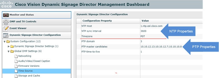
4.![]() (Optional) Change the global PTP properties as required for your network. Refer to Table 2.
(Optional) Change the global PTP properties as required for your network. Refer to Table 2.
5.![]() (Optional) Change the global NTP properties as required for your environment. Refer to Table 3.
(Optional) Change the global NTP properties as required for your environment. Refer to Table 3.
6.![]() Click the disk icon to Save changes.
Click the disk icon to Save changes.
Verifying PTP Operation for the Series 2 and Series 3 Media Player
This section describes how to verify the PTP configuration and also the operation of PTP for your Series 2 and Series 3 devices.
To verify the PTP operation for the Series 2 and Series 3 media player:
1.![]() Open your browser and navigate to one of the DMPs:
Open your browser and navigate to one of the DMPs:
http:// sv4k-ip-address /ptp.html
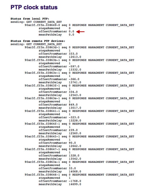
2.![]() Identify the PTP master by finding the unit that has an “offsetFromMaster” value of 0.0.
Identify the PTP master by finding the unit that has an “offsetFromMaster” value of 0.0.
Figure 2 highlights the PTP master and shows a network where PTP is operating successfully with 12 members.
Figure 2 Successful PTP Clock Operation
 Feedback