- About This Guide
- Getting Started with the Series 2 and Series 3 Media Player
- Planning the Series 2 and Series 3 Media Player Deployment
- Deploying the Series 2 and Series 3 Media Player
- Verifying the Deployment of the Series 2 and Series 3 Media Player
- Monitoring and Maintaining the Series 2 and Series 3 Media Player
- Troubleshooting the Series 2 and Series 3 Media Player
- Appendix A: Management Dashboard Commands for the Series 2 and Series 3 Media Player
- Appendix B: Display Parameters for the Series 2 and Series 3 Media Players
- Appendix C: Configuring an IOS DHCP Server to Support the Series 2 and Series 3
Release 6.1: Cisco Vision Deployment Guide for Series 2 and Series 3 Media Players: Dynamic Signage Director
Bias-Free Language
The documentation set for this product strives to use bias-free language. For the purposes of this documentation set, bias-free is defined as language that does not imply discrimination based on age, disability, gender, racial identity, ethnic identity, sexual orientation, socioeconomic status, and intersectionality. Exceptions may be present in the documentation due to language that is hardcoded in the user interfaces of the product software, language used based on RFP documentation, or language that is used by a referenced third-party product. Learn more about how Cisco is using Inclusive Language.
- Updated:
- July 11, 2018
Chapter: Planning the Series 2 and Series 3 Media Player Deployment
- Workflow Summary to Plan Deployment of the Series 2 and Series 3 Media Players
- Zones, Groups and Locations Planning
- TV Planning for the Series 2 and Series 3 Media Player
- TV Requirements for Series 2 and Series 3 Compliance
- TV Qualification for HDMI CEC Control of TV Power On/Off
- Guidelines for TVand Content Resolution with the Series 2 and Series 3 Media Players
- Restrictions for Control Panel TV Display Specifications with the Series 2 and Series 3 Media Players
- Configuring Resolution Under Control Panel Display Specifications
- Network and Switch Planning
Planning the Series 2 and Series 3 Media Player Deployment
Series 2 DMPS: DMP-2K and SV-4K
Series 3 DMPs: CV-HD and CV-UHD
This module describes aspects of the Series 2 and Series 3 deployment to consider and execute—before you install and provision the Series 2 and Series 3 media players. It is for installers, network administrators, and administrators of Cisco Vision Dynamic Signage Director.
This module includes the following topics:
■![]() Workflow Summary to Plan Deployment of the Series 2 and Series 3 Media Players
Workflow Summary to Plan Deployment of the Series 2 and Series 3 Media Players
■![]() Zones, Groups and Locations Planning
Zones, Groups and Locations Planning
■![]() TV Planning for the Series 2 and Series 3 Media Player
TV Planning for the Series 2 and Series 3 Media Player
Workflow Summary to Plan Deployment of the Series 2 and Series 3 Media Players
Table 1 provides a summary of the tasks and related information to plan for the deployment of the SV-4K media player.
|
|
|
|---|---|
|
|
|
|
|
■ ■ ■ |
|
|
■ |
|
|
■ ■ |
|
|
|
|
|
|
|
|
|
Zones, Groups and Locations Planning
Note: We do not recommend mixed groups that contain different media player device types. Cisco Vision Dynamic Signage Director gives a warning about such groups if you attempt to configure them.
TV Planning for the Series 2 and Series 3 Media Player
This section includes the following topics:
■![]() TV Requirements for Series 2 and Series 3 Compliance
TV Requirements for Series 2 and Series 3 Compliance
■![]() TV Qualification for HDMI CEC Control of TV Power On/Off
TV Qualification for HDMI CEC Control of TV Power On/Off
■![]() Guidelines for TV and Content Resolution with the Series 2 and Series 3 Media Players
Guidelines for TV and Content Resolution with the Series 2 and Series 3 Media Players
■![]() Restrictions for Control Panel TV Display Specifications with the Series 2 and Series 3 Media Players
Restrictions for Control Panel TV Display Specifications with the Series 2 and Series 3 Media Players
■![]() Configuring Resolution Under Control Panel Display Specifications
Configuring Resolution Under Control Panel Display Specifications
TV Requirements for Series 2 and Series 3 Compliance
For the optimal experience with the Series 2 and Series 3 media player, verify the site TV displays are compliant with the following specifications and resolution:
■![]() High-bandwidth Digital Content Protection (HDCP)
High-bandwidth Digital Content Protection (HDCP)
■![]() High-Definition Multimedia Interface (HDMI)
High-Definition Multimedia Interface (HDMI)
■![]() HDMI Consumer Electronics Control (CEC) (as required for TV control)
HDMI Consumer Electronics Control (CEC) (as required for TV control)
TV Qualification for HDMI CEC Control of TV Power On/Off
We introduced support for the universal TV power on/off HDMI CEC command on the Cisco DMPs with a new Display Specifications configuration that allows you to control the following three TV functions through HDMI CEC:
When HDMI CEC TV control is enabled, HDMI CEC is used instead of RS-232 for TV control functions. For information about accessing and setting up this parameter, see Configuring HDMI-CEC TV Control in TV Display Specifications in the Cisco Vision Dynamic Signage Director Operations Guide, Release 6.0.
Note: Not all TVs support the standard HDMI CEC commands. Test the TV models that you plan to install for support of HDMI CEC and turn HDMI-CEC on. TV manufacturers refer to CEC by different trade names. (For example: Anynet+ [Samsung], BRAVIA Link [Sony], EasyLink [Phillips], and SimpLink [LG]).
For information about some of the TV models that have been tested with Cisco Vision Dynamic Signage Director, see Release Notes for Cisco Vision Dynamic Signage Director, Release 6.0.
Guidelines for TV and Content Resolution with the Series 2 and Series 3 Media Players
The Series 2 and Series 3 are set to run in full high-definition (HD) 1920x1080 mode by the runtime software.
Note: We highly recommend that your TV supports a minimum of 1080p HD resolution. Lower resolution displays might need some additional configuration of the TV Display Specification configuration in Cisco Vision Dynamic Signage Director to attempt to optimize the display. In some cases these TVs might cut off an area of the screen, rather than resize the graphics.
The quality and expected resolution for video and graphics display for the Series 2 and Series 3 can be affected by several things:
■![]() The resolution of the TV display and its ability to negotiate to 1080p.
The resolution of the TV display and its ability to negotiate to 1080p.
■![]() The configuration of the sv4k.videoMode serial command in the Display Specifications area of the Cisco Vision Dynamic Signage Director Control Panel:
The configuration of the sv4k.videoMode serial command in the Display Specifications area of the Cisco Vision Dynamic Signage Director Control Panel:
–![]() When set to a resolution, this value specifies the Series 2 and Series 3 signal resolution.
When set to a resolution, this value specifies the Series 2 and Series 3 signal resolution.
–![]() If the resolution is set to auto-detection, then the TV negotiates the signal resolution with the Series 2 and Series 3, as long as the TV supports negotiation.
If the resolution is set to auto-detection, then the TV negotiates the signal resolution with the Series 2 and Series 3, as long as the TV supports negotiation.
Note: If you are using a 4K display, you must configure a fixed resolution value of 3840x2160x60p in the sv4k.videoMode serial command in the TV display specification.
■![]() The size of the original graphic and whether any scaling needs to happen.
The size of the original graphic and whether any scaling needs to happen.
Note: For more information about content and template guidelines, see the Cisco Vision Content Planning and Specification Guide: Dynamic Signage Director, Release 6.1.
Restrictions for Control Panel TV Display Specifications with the Series 2 and Series 3 Media Players
Before you configure TV display specifications for use with the Series 2 and Series 3 media players, consider the following restrictions:
Configuring Resolution Under Control Panel Display Specifications
The Display Specification for a TV can either be configured for auto-detection of resolution by the TV, or set to a fixed resolution in the Cisco Vision Dynamic Signage Director Control Panel.
Figure 1 Series 2 and Series 3 and Display Signal Resolution
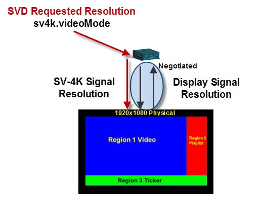
■![]() If the resolution is set to auto-detection, then the TV and the Series 2 and Series 3 negotiate the signal resolution, as long as the TV supports auto-negotiation (Figure 1).
If the resolution is set to auto-detection, then the TV and the Series 2 and Series 3 negotiate the signal resolution, as long as the TV supports auto-negotiation (Figure 1).
■![]() If a resolution is specified in the Control Panel, then the content is resized according to that setting. This is the requested Series 2 and Series 3 signal resolution shown in red in Figure 1.
If a resolution is specified in the Control Panel, then the content is resized according to that setting. This is the requested Series 2 and Series 3 signal resolution shown in red in Figure 1.
■![]() If the signal resolution of the Series 2 and Series 3 is set below 1920x1080 for any reason, video content will be resized according to the template in use.
If the signal resolution of the Series 2 and Series 3 is set below 1920x1080 for any reason, video content will be resized according to the template in use.
■![]() The template in use and the corresponding content must match the signal resolution.
The template in use and the corresponding content must match the signal resolution.
Note: The sv4k.videoMode display parameter is unrelated and is not a required or expected configuration for use of portrait mode. In addition, only certain values are supported for sv4k.videoMode, and they should not be changed to any other values ( Table 2). Portrait mode is enabled and configured using the dmp.portrait display parameter only. However, when preparing your content for portrait mode, the content should be designed for 1920 pixels high and 1080 pixels wide. The default template canvas will still show horizontal orientation when you are using portrait mode, but you can add regions that extend beyond the canvas.
To set the resolution for a display:
1.![]() Go to Control Panel > Setup > Devices > Display Specifications.
Go to Control Panel > Setup > Devices > Display Specifications.
2.![]() Select the TV that you want to configure.
Select the TV that you want to configure.
3.![]() Click the Display Parameters tab.
Click the Display Parameters tab.
4.![]() Find the sv4k.videoMode command (Figure 2) and select it.
Find the sv4k.videoMode command (Figure 2) and select it.
Figure 2 Resolution Setting in Display Specifications
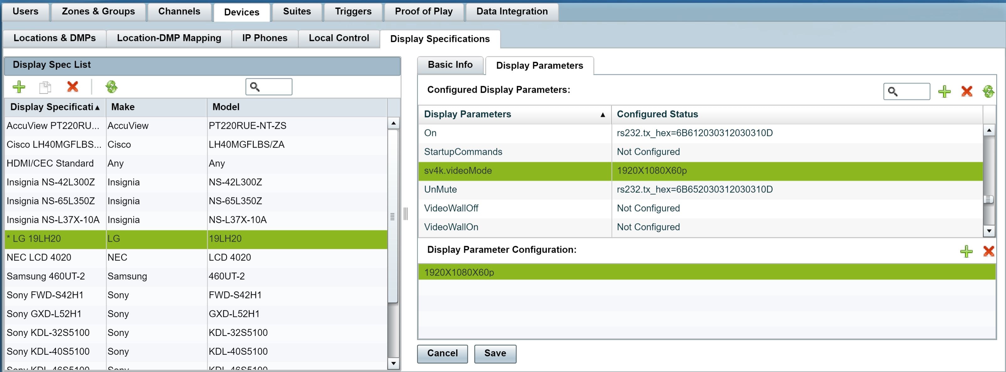
5.![]() Click the green “plus sign” to add in the specs in the Display Parameter Configuration field. Specify one of the values in Table 2 according to the desired resolution behavior.
Click the green “plus sign” to add in the specs in the Display Parameter Configuration field. Specify one of the values in Table 2 according to the desired resolution behavior.
|
|
|
|---|---|
|
|
|
|
|
|
|
|
|
|
|
|
|
|
|
Network and Switch Planning
This section includes the following topics:
■![]() External DHCP Server Requirements
External DHCP Server Requirements
■![]() Connected Stadium Switch Requirements
Connected Stadium Switch Requirements
External DHCP Server Requirements
The Series 2 and Series 3 medias player require configuration of an external DHCP server to provide IP addressing to the devices. This service can be configured using Cisco Network Registrar (CNR) or another external server at the venue.
This section highlights some of the key requirements to plan your DHCP configuration. However, it does not describe all of the details for you to perform the configuration.
Note: For more information and details about DHCP configuration, see the Cisco Vision Dynamic Signage Solution Operation and Network Requirements available to qualified Cisco Vision partners.
DHCP Configuration Guidelines for the Series 2 and Series 3 Media Player
Consider the following guidelines before configuring a DHCP server for the Series 2 and Series 3 :
■![]() Do not configure the Connected Stadium Switch as the IOS DHCP server for Cisco Vision Dynamic Signage Director.
Do not configure the Connected Stadium Switch as the IOS DHCP server for Cisco Vision Dynamic Signage Director.
■![]() Be sure to set the DHCP server for an infinite lease of IP addresses to the Series 2 and Series 3 devices.
Be sure to set the DHCP server for an infinite lease of IP addresses to the Series 2 and Series 3 devices.
■![]() If you are supporting a deployment with mixed models of media players, configure an Option 60 string for each model.
If you are supporting a deployment with mixed models of media players, configure an Option 60 string for each model.
■![]() If the DHCP server is limited to a single Option 43 string per DHCP pool (such as with a Cisco DHCP server), configure a separate DHCP scope for each media player model.
If the DHCP server is limited to a single Option 43 string per DHCP pool (such as with a Cisco DHCP server), configure a separate DHCP scope for each media player model.
■![]() Configure the DHCP Option 60, Vendor Class Identifier string:
Configure the DHCP Option 60, Vendor Class Identifier string:
–![]() CV-HD global string: “Cisco CV-HD”
CV-HD global string: “Cisco CV-HD”
–![]() CV-UHD global string: “Cisco CV-UHD”
CV-UHD global string: “Cisco CV-UHD”
–![]() CV-UHD with WiFi global string: “Cisco CV-UHD-WiFi”
CV-UHD with WiFi global string: “Cisco CV-UHD-WiFi”
–![]() DMP-2K string for new, factory-shipped devices: “Cisco DMP-2K”
DMP-2K string for new, factory-shipped devices: “Cisco DMP-2K”
–![]() SV-4K string for North America: “Cisco SV-4K-NA”
SV-4K string for North America: “Cisco SV-4K-NA”
–![]() SV-4K string for all other regions: “Cisco SV-4K-ROW”
SV-4K string for all other regions: “Cisco SV-4K-ROW”
■![]() Configure the converted DHCP Option 43, Vendor Specific Option URL:
Configure the converted DHCP Option 43, Vendor Specific Option URL:
http:// x.x.x.x :8080/StadiumVision/dmp_v4/scripts/boot.brs
where “ x.x.x.x ” is the IP address of the Dynamic Signage Director server.
Note: The option 43 string must be converted to TLV format for compatibility with the Series 2 and Series 3. For more information, see Appendix C: Configuring an IOS DHCP Server to Support the Series 2 and Series 3 Media Players.
Connected Stadium Switch Requirements
This section highlights some of the key requirements to plan your Connected Stadium switch configuration. However, it does not describe all of the details for you to perform the configuration. For configuration details, see the Cisco Vision Dynamic Signage Solution Operation and Network Requirements available to qualified Cisco Vision partners.
Switch Configuration Requirements for the Series 2 and Series 3 Media Player
Be sure that the Connected Stadium switch meets the following configuration requirements to support the deployment of the Series 2 and Series 3 media players:
■![]() Supports PoE+ (IEEE 802.3at) with 30W of port power.
Supports PoE+ (IEEE 802.3at) with 30W of port power.
■![]() Configures Internet Group Management Protocol (IGMP).
Configures Internet Group Management Protocol (IGMP).
■![]() IGMPv1, IGMPv2, and IGMPv3 are supported.
IGMPv1, IGMPv2, and IGMPv3 are supported.
■![]() Configures Link Layer Discovery Protocol (LLDP), which is required to determine available power using PoE+ and also supports the IOS Civic Location feature.
Configures Link Layer Discovery Protocol (LLDP), which is required to determine available power using PoE+ and also supports the IOS Civic Location feature.
Note: For more information and details about the switch configuration, see the Cisco Vision Dynamic Signage Solution Operatoin and Network Requirements available to qualified Cisco Vision partners.
 Feedback