Installation Overview

Performing a Preinstallation Configuration (Optional)

The following procedures describe the processes to ensure that your AP installation and initial operation go as expected.


Note


Performing a preinstallation configuration is an optional procedure. If your network controller is properly configured, you can install your AP in its final location and connect it to the network from there.
The following illustration shows the preinstallation configuration setup:

Perform the following steps:

Before you begin

Ensure that the Cisco Controller Distribution System (DS) port is connected to the network. Use the procedure for CLI or GUI as described in the release appropriate Cisco Catalyst 9800 Series Wireless Controller Software Configuration Guide.
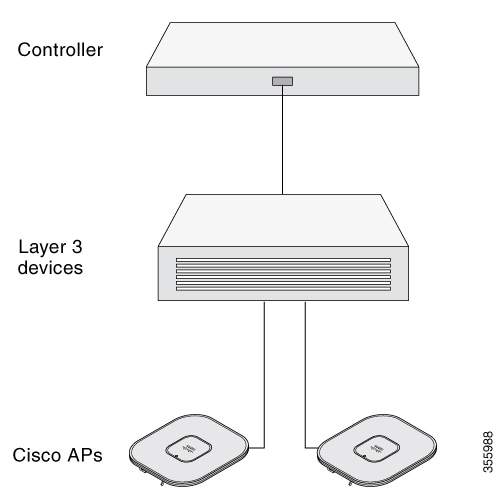
  • Enable Layer 3 connectivity between APs, Cisco Controller Management, and AP-Manager interface.

  • Configure the switch to which your AP has to attach. See the Cisco Wireless Controller Configuration Guide for the release you are using, for additional information.

  • Configure the Cisco Catalyst 9800 Series Wireless Controller as the primary so that new APs always join it.

  • Ensure that the DHCP is enabled on the network. The AP must receive its IP address through DHCP.


    Note


    An 802.11ax AP is assigned an IP address from the DHCP server only if a default router (gateway) is configured on the DHCP server (enabling the AP to receive its gateway IP address) and the gateway ARP is resolved.
  • CAPWAP UDP ports must not be blocked in the network.

  • The AP must be able to find the IP address of the controller. This can be accomplished using DHCP, DNS, or IP subnet broadcast. This guide describes the DHCP method to convey the controller IP address. For other methods, see the product documentation.


    Note


    The AP requires a multi-gigabit Ethernet (5 Gbps) link to prevent the Ethernet port from becoming a bottleneck for traffic.

Procedure


Step 1

Power the AP using supported power source.

  • As the AP attempts to connect to the controller, the LED cycles through a green, red, and off sequence, which can take up to five minutes.

    Note

     
    If the AP remains in this mode for more than five minutes, the AP cannot find the primary Cisco Catalyst 9800 Series Wireless Controller. Check the connection between the AP and the Cisco Catalyst 9800 Series Wireless Controller and be sure that they are on the same subnet.
  • If the AP shuts down, check the power source.

  • After the AP finds the Cisco Catalyst 9800 Series Wireless Controller, it attempts to download the new operating system code if the AP code version differs from the Cisco Catalyst 9800 Series Wireless Controller code version. While this is happening, the Status LED blinks blue.

If the operating system download is successful, the AP reboots.

Step 2

(Optional) Configure the AP. Use the controller CLI, GUI, or Cisco DNA Center to customize the access point-specific 802.11ax network settings.

Step 3

If the preinstallation configuration is successful, the Status LED is green, indicating normal operation. Disconnect the AP and mount it at the location at which you intend to deploy it on the wireless network.

Step 4

If your AP does not indicate normal operation, turn it off and repeat the preinstallation configuration.

Note

 
When you are installing a Layer 3 access point on a subnet that is different from the Cisco Catalyst 9800 Series Wireless Controller, ensure the following setup is configured:
  • A DHCP server is reachable from the subnet on which you plan to install the AP.

  • The subnet has a route back to the controller.

  • This route has destination UDP ports 5246 and 5247 open for CAPWAP communications.

  • The route back to the primary, secondary, and tertiary controller allows IP packet fragments.

  • If address translation is used, the access point and the controller have a static 1-to-1 NAT to an outside address. Port Address Translation is not supported.


Preinstallation Checks and Installation Guidelines

Before you mount and deploy your access point, we recommend that you perform a site survey (or use the Site Planning tool) to determine the best location to install your access point.

You should have the following information about your wireless network available:

  • Access point locations

  • Access point mounting options: To a vertical or horizontal wall or a pole

  • Access point power options: Use either of the following options to power the AP:

    • DC power input

    • Cisco-approved power injector

    • 802.3at (PoE+), 802.3bt, and Cisco Universal PoE (Cisco UPOE)

  • Operating temperature: -40° to +131°F (-40° to +55°C) with solar load and still air.

    Extended operating temperature (DC powered): -58° to +149°F (-50° to +65°C) without solar loading, still air, and cold start limited to -40°C

  • Console access using the console port

    We recommend that you use a console cable that is one meter or less in length.


    Note


    The AP may face issues while booting if you use an unterminated console cable (not plugged into any device or terminal) or a console cable that is more than one meter in length.

We recommend that you make a site map showing access point locations so that you can record the device MAC addresses from each location and return them to the person who is planning or managing your wireless network.


Note


Professional installation is required.


Mounting the Access Point

This section provides instructions to mount the AP.


Note


Personnel mounting the AP must have knowledge of the wireless AP, bridging techniques, and grounding methods.


Mounting Hardware

The IW9167I access point has built-in mounting flanges. You can also use the following mounting hardware:

  • DIN rail mounting bracket

  • Pole mounting bracket

Required mounting hardware depends on the mounting location:

  • For ceilings or hard ceilings or walls, directly mount the access point using the built-in mounting flanges.

The mounting flanges are on the sides of the access point that are without ports.

  • For electrical cabinets or network boxes, directly mount the access point using the mounting flanges or use the DIN rail mounting bracket.

  • For pole mounting, use the pole mounting bracket.

Mounting Bracket Part Numbers


Note


These brackets do not ship with the access point, but you can order them separately.
Table 1. Mounting Bracket Part Numbers

Mounting Bracket

Cisco Part Number

DIN Rail Mounting Bracket

AIR-ACCDMK3700=

Pole Mounting Bracket (for 2”–3.2” diameter pole)

AIR-ACCPMK3700=

Pole Mounting Bracket (for 2”–16” diameter pole)

AIR-ACCPMK3700-2=

Horizontal Pole Mounting Bracket

IW-ACC-9167I-BRK=

Using the Integrated Flange Mounts

Direct mounting using the integrated flange mounts is typically for confined spaces or deployments that experience severe shock and vibration.

To mount the access point using the integrated flange mounts:

Procedure


Step 1

Choose the access point location that can safely support the weight of the access point.

Step 2

Use the access point mounting holes as a template, and mark them at the mounting location.

1

Main mounting flange

2

Mounting holes

Step 3

Drill holes on the mounting surface for plastic wall anchors to suit 1/4-20 or M6 bolts, and add the appropriate anchors.

Step 4

Align the access point mounting holes with the drilled holes.

Step 5

Insert a mounting screw in each of the four mounting holes and tighten.

Step 6

You can use the keyholes for “hands-free” installation.

Note

 
Ensure that the access point is firmly secured.

Using the DIN Rail Mounting Bracket

You can use DIN rail mounting in network or electrical closets or cabinets, or in wiring rooms that have low-levels of shock and vibration. The following figure shows the DIN rail and DIN rail mounting assembly.

Figure 1. DIN Rail Mounting Assembly

1

35 mm DIN rail (not supplied by Cisco)

2

DIN rail mounting bracket clip

To DIN rail mount the access point:

Procedure


Step 1

Assemble the access point and DIN rail mounting bracket using the M6 hardware supplied as shown in the following figure.

1

Steel DIN mounting bracket

3

M6 screw (Torque 6–7 ft-lbs)

2

M6 insert

4

Access Point

Step 2

Position the access point assembly directly in front of the DIN rail.

Step 3

Insert the DIN rail mounting bracket under the spring-loaded upper mounting clips.

Note

 
Ensure that the DIN rail seats into the anti-slip clips.

Step 4

Pull down the retention handles until the lower lip of the DIN rail mounting bracket seats in the lower mounting bracket clip.

Step 5

Release the retention handles.


Using the Pole Mounting Bracket

You can choose one of the following pole mounting brackets in the following table, according to the size of the pole that you are going to mount your access point on.

Table 2. Pole Mounting Brackets

Mounting Bracket

Cisco Part Number

Applicable Pole Diameter

Pole Mounting Bracket

AIR-ACCPMK3700=

2–3.2 inches

Pole Mounting Bracket 2

AIR-ACCPMK3700-2=

2–16 inches

Using the Mounting Bracket AIR-ACCPMK3700=

To mount the access point on a pole using the mounting bracket AIR-ACCPMK3700=:

Procedure

Step 1

Use the supplied U bolts, washers, and nuts to attach the mounting bracket to the pole.

1

2"– 3.2" (5–8 cm) diameter pole

3

M8 x 1.25 nuts and washers

2

M8 x 1.25 U-bolt

4

Pole mounting bracket

Step 2

Use the included bolts, washers, and nuts to attach the access point to the mounting plate.

Note

 
Ensure that you symmetrically tighten the nuts on the U-bolts. If you over tighten one side, the U-bolt will skew.

Step 3

Torque the nuts to 6 to 7 foot-pounds.

1

Access point

3

Pole mounting bracket

2

M6 bolts and washers

4

2"– 3.2" (5–8 cm) diameter pole

Note

 
Ensure that the access point is firmly secured to the mounting bracket.

You can use the keyholes for “hands-free” installation. Ensure that you torque the nuts to 6 to 7 ft-lbs.

Caution


Never leave the access point unattended if the mounting hardware is not torqued to full value.


Using the Mounting Bracket AIR-ACCPMK3700-2=

The mounting bracket AIR-ACCPMK3700-2= supports poles from 2 to 16 inches in diameter. To mount the access point on a pole using this mounting bracket:

Procedure

Step 1

Assemble two strap brackets on the pole clamp bracket that are positioned for the pole diameter you are using to mount the access point. The following image illustrates the pole diameter indicators and bolt holes on the pole clamp bracket.

Figure 2. Pole Clamp Bracket Adjustment Hole Locations

1

Pole size indicators

  • 2 to 6 in.

  • 6 to 11 in.

  • 11 to 16 in.

2

Bolt holes for pole diameters (11 to 16 inches indicated)

Step 2

Position the strap brackets on the pole clamp bracket for the pole diameter you are using and secure each strap bracket with two M8 x16 bolts (with lock washers), as the following image shows. Tighten the bolts to 13 to 15 ft lbs (17.6 to 20.3 N-m).

Figure 3. Assembled Pole Clamp Bracket and Strap Brackets

1

M8 x1.25x16 bolts (with lock washers)

3

Strap bracket (shown positioned for 11 to 16 inch diameter pole)

2

Pole clamp bracket

Step 3

Screw the M8 nut onto the pole clamp bracket support bolt, and tighten just enough to prevent the bolt from falling off.

Step 4

To mount your access point on a vertical pole, you need to install two metal bands around the pole to support the access point. This process requires extra tools and material not provided in the pole mount kit (see the following table for details).

Table 3. Material Needed to Mount Access Point on a Pole

Mounting Method

Materials Required

In Kit

Vertical pole

  • Two 0.75-in (1.9 cm) stainless steel bands

  • Banding strap tool (BAND IT) (Cisco AIR-BAND-INST-TL=)

  • Ground lug (provided with access point)

  • Crimping tool for ground lug, Panduit CT-720 with CD-720-1 die (http://onlinecatalog.panduit.com)

  • #6 AWG ground wire

Yes

No

Yes

No

No

Step 5

Select a mounting location on the pole to mount the access point. You can attach the access point to any pole from 2 to 16 inch (5.1 to 40.6 cm) in diameter.

Step 6

For poles larger than 3.5 inch (8.9 cm), mount the pole clamp bracket assembly to a pole (see the following image) using two metal straps. Following the instructions provided with the banding strap tool (BAND IT) (AIR-BAND-INST-TL=), loop each metal strap twice through the slots on the strap bracket.

Caution


Do not place the metal straps in the large open area between the pole clamp bracket and the strap brackets, because this does not properly secure the access point.

Figure 4. Clamp Bracket Assembly Mounted on Poles Larger than 3.5 inch (8.9 cm)

1

Pole clamp bracket

3

Metal mounting strap

2

Strap slot in strap bracket

4

Pole

Step 7

For pole diameters of 3.5 inch (8.9 cm) or less, mount the pole clamp bracket assembly to a pole using two metal straps looped through the space between the pole clamp bracket and the strap brackets to provide maximum holding strength for extreme environments. Following the instructions provided with the banding strap tool (BAND IT) (AIR-BAND-INST-TL=), loop each metal strap twice.

Caution


Do not place the metal straps in the large open area between the pole clamp bracket and the strap brackets because this does not properly secure the access point.

Step 8

Position the pole clamp bracket on the pole as needed before tightening the metal bands.

Note

 
When the metal bands are tightened to the full tension, the pole clamp bracket cannot be adjusted unless the metal bands are cut or disassembled.

Step 9

Tighten the metal bands using the banding strap tool (BAND IT) (Cisco AIR-BAND-INST-TL=) by following the operating instructions in the box with the tool. Ensure that the metal bands are as tight as possible.

Step 10

Place the mounting bracket onto the pole clamp bracket support bolt.

Step 11

Install four M8 x16 bolts (with flat and lock washers) into the bolt holes.

Figure 5. Mounting Bracket and Pole Clamp Bracket Assembly

1

Pole clamp bracket assembly

3

Bolt holes

2

Access point support bolt

4

Mounting bracket

Step 12

Hand-tighten the bolts and the nut (do not overtighten).

Step 13

Adjust the top edge of the mounting bracket until it is horizontal and tighten the bolts and the flange nut to 13 to 15 ft-lbs (17.6 to 20.3 N-m).

Step 14

Use the included bolts, washers, and nuts to attach the access point to the mounting plate.

Step 15

Torque the nuts to 6 to 7 ft-lbs.

Figure 6. Access Point Installed in the Mounting Bracket

1

Access point

3

Pole mounting bracket

2

M6 bolts and washers

4

Pole

Note

 
Ensure that the access point is firmly secured to the mounting bracket.

Caution


Never leave the access point unattended if the mounting hardware is not torqued to full value.


Using Horizontal Mounting Bracket (AIR-MNT-HORZ1=)

Use the AIR-MNT-HORZ1= mounting bracket to mount the AP horizontally on a wall or a pole.

1

Wall mount holes

4

Band clamp slots

2

M6 bolts

5

L-Mount Bracket

3

Access Point

Wall Mount using Horizontal Mount Bracket

The AIR-MNT-HORZ1= mounting kit contains a mounting L-bracket and components for both pole mounting and wall mounting. Using this kit, you can install the AP to a wall using bolts.

Before you begin

Table 4. Materials for Mounting AP to a Wall

Materials Needed

Supplied in the Kit?

Tightning Value

Wall/Pole mounting L-bracket

Yes

(4x) M6 x 12 mm Hex-head bolts

Yes

4.5 Nm

(4x) wall screws or anchors (specific for wall material)

No

Drill bit for wall anchors

No

10 mm box-end wrench or socket set

No

Phillirs Screwdriver

No

Procedure


Step 1

Use the mounting bracket as a template to mark four screw hole locations on the mounting wall.

Step 2

Use four screws and, if required, wall anchors to attach the L-bracket to the mounting surface. You must procure these screws and anchors, and they must follow local codes to support at least 50 lbs (22.7 kg.)

Step 3

Position the AP horizontally against the L-bracket's bottom to align the four mounting holes on the AP’s back with the slots in the mounting bracket.

Step 4

Screw an M6 x12–mm bolt into each of the four support bolt holes on the back of the AP by hand.

Do not tighten the bolt completely. Leave it loose to slide in the bracket slot.

Step 5

Ensure that the AP and all attached cables have clearance to install and provide drip loops.

Step 6

Access Point must be tethered using a safety strap to the wall through either of the two holes (1).

Note

 
  • Tethering the access point to the wall is a critical safety step that must not be overlooked.

  • Push the access point as close to the wall as possible.

1

Tethering holes

2

Screws installed in its slots

Step 7

Tighten the four M6 bolts to 40–lbf-in (4.5 Nm) torque using a 10–mm wrench.


Pole Mount using Horizontal Mount Bracket

The AIR-MNT-HORZ1= mounting kit contains a mounting L-bracket and components for both pole mounting and wall mounting. Using this kit, you can install the AP on a pole or mast. It supports metal, wood, or fiberglass poles from 2 to 5 inches (51 to 127 mm) in diameter.

Before you begin

Table 5. Materials for Mounting AP to a Pole

Materials Needed

Supplied in the Kit?

Tightning Value

Wall/Pole mounting L-bracket

Yes

(4x) M6 x 12 mm Hex-head bolt

Yes

4.5 Nm

(4x) wall screws or anchors (specific for wall material)

No

Drill bit for wall anchors

No

10 mm box-end wrench or socket set

No

Phillirs Screwdriver

No

Procedure


Step 1

Select a mounting location on the pole to mount the AP. You can attach the AP to a pole with a diameter of 2 to 5 inch (51 to 127 mm).

Step 2

Hold the bracket up against the pole, slide the two band straps through the top and bottom sets of mounting slots on the mounting bracket.

Step 3

Wrap the band straps around the pole, lock them, and lightly tighten the clamps using a wrench. Only tighten them enough to keep the bracket from sliding down the pole.

Step 4

Position the AP horizontally against the L-bracket's bottom to align the four mounting holes on the AP’s back with the slots in the mounting bracket.

Step 5

Screw an M6 x12–mm bolt into each of the four support bolt holes on the back of the AP by hand. Do not completely tighten the bolt. Leave it loose to slide in the bracket slot.

Do not tighten the bolt completely. Leave it loose to slide in the bracket slot.

Step 6

Hold the AP position to its final position. Tighten the band clamps with the wrench so that the AP does not slide or rotate on the pole.

Ensure that the clamps are tight enough not to let the AP move. Ensure that the AP and all attached cables have clearance to install and provide drip loops.

Step 7

Access Point must be tethered using a safety strap to the pole through either of the two holes (1).

Note

 
  • Tethering the access point to the pole is a critical safety step that must not be overlooked.

  • Push the access point as close to the pole as possible.

1

Tethering holes

2

Screws installed in its slots

Step 8

Using a 10–mm wrench, tighten the four M6 bolts to 40–lbf-in (4.5 Nm) torque.


Attaching a Power Adapter

If you want to attach a power adapter (IW-PWRADPT-MFIT4P=) to the access point on a pole using the mounting bracket AIR-ACCPMK3700= or AIR-ACCPMK3700-2=, use the procedures in the following sections.

Attaching a Power Adapter Using the Mounting Bracket AIR-ACCPMK3700=

To attach a power adapter (IW-PWRADPT-MFIT4P=) to the access point on a pole using the mounting bracket AIR-ACCPMK3700=, use the following procedures:

Procedure


Step 1

Ensure you have the mounting bracket set up as described in Step 1 of Using the Mounting Bracket AIR-ACCPMK3700-2=.

Step 2

Attach the power supply using 4x 6-32 screws and torque the screws to 8.3-11 in-lbs, as shown in the following figure.

Figure 7. Power Adapter Installed Using Mounting Bracket AIR-ACCPMK3700=

1

Power Adapter

3

DC Output Cable

2

Tie Wraps

4

10 inches Minimum Length

Step 3

Ensure that the excess cable is bundled and tie wrapped to the mounting bracket. Route the cable as shown in the figure in Step 2.

Step 4

Ensure that there is 10 inches minimum length from the bottom edge of the power supply to the end of the connector as shown in the figure in Step 2.

Step 5

Attach the access point to the mounting plate as described in Step 2 and Step 3 of Using the Mounting Bracket AIR-ACCPMK3700-2=.


Attaching a Power Adapter Using the Mounting Bracket AIR-ACCPMK3700-2=

To attach a power adapter (IW-PWRADPT-MFIT4P=) to the access point on a pole using the mounting bracket AIR-ACCPMK3700-2=, use the following procedures:

Procedure


Step 1

Ensure you have the mounting bracket set up as described in Step 1 through Step 13 of Using the Mounting Bracket AIR-ACCPMK3700-2=. But for step 11, the 2 lower bolts need to be repositioned to the locations indicated as No. 6 in the following figure.

Step 2

Attach the power supply using 4x 6-32 screws and torque the screws to 8.3-11 in-lbs, as shown in the following figure.

Figure 8. Power Adapter Installed Using Mounting Bracket AIR-ACCPMK3700-2=

1

Power Adapter

4

10 inches Minimum Length

2

Tie Wraps

5

4x 6-32 Screws

3

DC Output Cable

6

Reposition the bolts

Step 3

Ensure that the excess cable is bundled and tie wrapped to the mounting bracket. Route the cable as shown in the figure in Step 2.

Step 4

Ensure that there is 10 inches minimum length from the bottom edge of the power supply to the end of the connector as shown in the figure in Step 2.

Step 5

Attach the access point to the mounting plate as described in step 14 and step 15 of Using the Mounting Bracket AIR-ACCPMK3700-2=.


Grounding the Access Point

In all installations, after mounting the access point, you must properly ground the unit before connecting power cables.


Warning


This equipment must be grounded. To reduce the risk of electric shock, never defeat the ground conductor or operate the equipment in the absence of a suitably installed ground conductor. Contact the appropriate electrical inspection authority or an electrician if you are uncertain that suitable grounding is available.


Warning


To reduce risk of electric shock or fire, installation of the equipment must comply with local and national electrical codes.


The access point is shipped with a grounding kit.

Figure 9. Access Point Grounding Kit Contents

1

Grounding lug

2

Screws x 2, M4 x 6mm


Note


The grounding kit also includes the oxide inhibitor, which is contained in a tube.

To ground the access point:

Procedure


Step 1

Use a crimping tool to crimp a 6-AWG ground wire (not included in the grounding kit) to the ground lug.

Step 2

Connect the supplied ground lug to the access point ground connection point using the supplied screws. Apply supplied oxide inhibitor between the ground lug and the access point ground connection.

1

AP ground connection point

Step 3

Tighten the screws to 20-25 inch-lbs of torque.

Step 4

If necessary, strip the other end of the ground wire and connect it to a reliable earth ground such as a grounding rod or appropriate ground point on a grounded pole. Length of the ground cable should not exceed 1 meter, and 0.5 meter is preferred. Use supplied oxide inhibitor on the grounded interface.


Powering the Access Point

The AP supports these power sources:

  • DC power – 24–48 VDC

  • Power-over-Ethernet (PoE)

The AP can be powered via the PoE input from an inline power injector or a suitably powered switch port. Depending on the configuration and regulatory domain, the required power for full operation is 802.3bt or UPOE.

For more information, see Power Sources.

Power Feature Matrix

The following table provides the AP power feature matrix.

Table 6. Cisco Catalyst IW9167I Heavy Duty Access Point Power Feature Matrix

Power Input

2.4 GHz Radio

dBm Per Path

5 GHz Radio

dBm Per Path

6 GHz Radio

dBm Per Path

Aux Radio

GNSS

mGig Eth

SFP

24-48V

4x4

24

4x4

24

4x4

24

Yes

Yes

max 5G

Yes

802.3bt/ UPOE

4x4

24

4x4

24

4x4

17

Yes

Yes

max 5G

Yes

802.3at

2x2

23

2x2

23

2x2

17

Yes

Yes

max 1G

Yes/1G

Connecting a Power Injector

The AP supports the following power injectors:

Table 7. Supporting Power Injectors

Power Source

Description

AIR-PWRINJ-60RGD1=

60W rated outdoor power injector, with North America AC plug

AIR-PWRINJ-60RGD2=

60W rated outdoor power injector, global version without AC plug

IW-PWRINJ-60RGDMG=

60W rated outdoor power injector, 5GE

The power injector provides DC voltage to the AP over the Ethernet cable and supports a total end-to-end Ethernet cable length of 100 m (328 ft) from the switch to the AP.

When an optional power injector powers your AP, follow these steps to complete the installation:

Procedure


Step 1

Before applying PoE to the AP, ensure that the AP is grounded (see Grounding the Access Point).

Step 2

Connect a CAT5e or better Ethernet cable from your wired LAN network to the power injector.

Note


The installer is responsible for ensuring that powering the AP from this type of power injector is allowed by local and/or national safety and telecommunications equipment standards.

Step 3

Connect a shielded outdoor-rated Ethernet (CAT5e or better) cable between the power injector and the AP's PoE-in connector.

Step 4

Connect the Ethernet cable to the AP PoE-In port.


Connecting to the DC Power Port Using Cable Gland

Follow these steps to connect to the DC power port using cable gland:

Procedure


Step 1

Disassemble PG13 cable gland and slide parts over DC cable in the order shown in the following figure:

1

DC cable

4

Grommet

2

Gasket

5

Ferrule

3

PG13 body

6

Clamp nut

Step 2

Plug 4P connector cable into the DC connector in the chassis.

Step 3

Thread the PG13 body (with gasket) into the chassis.

Step 4

Insert the grommet into the ferrule, and press it into the PG13 body.

Step 5

Tighten the clamp nut onto the PG13 body until the grommet compresses onto the DC cable.

1

SFP port connected using cable gland

3

DC power port connected using cable gland

2

RJ-45 port connected using cable gland


Connecting DC Power Port Using M12 Adapter

Before you begin

O-rings are shipped separately from the M12 adapter. You need to place the o-ring on the adapter before installing the M12 adapter to the chassis.

Figure 10. Installing O-ring on the M12 Adapter

1

M12 adapter

2

O-ring

3

O-ring installed on M12 adapter

Procedure


Step 1

Place the O-ring on one side of the M12 adapter. Slightly stretch the o-ring and lift it over the other side. Avoid rolling the o-ring on to the adapter.

Step 2

Plug in DC connector into the chassis. Press M12-PWR adapter onto the chassis, and ensure that the wires are not pinched.

1

DC connector

3

M12-PWR adapter

2

Captive screws

Step 3

Tighten the M12-PWR adapter captive screws into the chassis. Torque to 15-20 in-lbs.

1

SFP port connected using M12 adapter

3

DC power port connected using M12 adapter

2

RJ45 port connected using M12 adapter


Connecting Data Cables

This AP supports data connections through the Ethernet port and the Small Form-factor Pluggable (SFP) port.

If you are using the SFP port to deliver data through a fiber-optic cable, the AP must be powered by DC power, power adapter, PoE+ power source, or a power injector.

For details on connecting to Ethernet port, see Connecting an Ethernet Cable to the Access Point.

For details on connecting to SFP port, see Connecting to the SFP Port of the Access Point.

Connecting an Ethernet Cable to the Access Point

Connect an Ethernet cable to the access point by using a cable gland or an M12-RJ45 adapter.

Connecting to the RJ45 Port Using Cable Gland

Follow these steps to connect to the RJ45 port using cable gland:

Procedure

Step 1

Disassemble PG13 cable gland and slide parts over RJ45 cable in the order shown in the following figure:

1

RJ45 cable

4

Grommet

2

Gasket

5

Ferrule

3

PG13 body

6

Clamp nut

Step 2

Plug the RJ45 cable into the RJ45 connector in the chassis.

Step 3

Thread the PG13 body (with gasket) into the chassis. The PG13 must be screwed into the chassis at this point.

Step 4

Insert the grommet into the ferrule, and press it into the PG13 body.

Step 5

Tighten the clamp nut onto the PG13 body until the grommet compresses onto the RJ45 cable.

1

SFP port connected using cable gland

3

DC power port connected using cable gland

2

RJ45 port connected using cable gland


Connecting to the RJ45 Port Using M12 Adapter

Follow these steps to connect to the RJ45 port using M12 adapter:

Procedure

Step 1

Ensure the O-ring is on the M12 adapter.

1

M12 adapter

2

O-ring

Step 2

Align the RJ45 tab with the RJ45 connector in the chassis, and plug the M12 adapter into thechassis.

1

Captive screws

2

M12-RJ45 adapter

Step 3

Tighten the M12 adapter captive screws into the chassis. Torque to 15-20 in-lbs.

1

SFP port connected using M12 adapter

3

DC power port connected using M12 adapter

2

RJ45 port connected using M12 adapter


Connecting to the SFP Port of the Access Point

Connect to the SFP port by using a cable gland or an M12-RJ45 adapter.


Note


Copper SFP or Fiber SFP will be detected by the system only after a power cycle.


Connecting to SFP Port Using Cable Gland

Follow these steps to connect to the SFP port using cable gland:

Procedure

Step 1

Insert the fiber SFP into the chassis.

Step 2

Disassemble the fiber adapter and slide parts over fiber cable in the order shown in the following figure:

1

Fiber SFP

5

Grommet

2

Fiber cable

6

Ferrule

3

O-Ring

7

Clamp nut

4

Adapter body

Step 3

Plug the fiber cable into the SFP.

Step 4

Thread the adapter body (with O-Ring) into the chassis.

Step 5

Insert the grommet into the ferrule, and press it into the adapter body.

Step 6

Tighten the clamp nut onto the adapter body until the grommet compresses onto the fiber cable.

1

SFP port connected using cable gland

3

DC power port connected using cable gland

2

RJ-45 port connected using cable gland


Using M12 Adapter on SFP Port

M12 adapter can be used only with a copper SFP and not supported with fiber SFP.

Follow these steps to connect M12 adapter to the SFP port:

Procedure

Step 1

Insert the copper SFP in the chassis.

Step 2

Ensure the O-rings are on the M12 adapter and spacer.

1

M12 adapter

2

O-ring

1

Spacer

2

O-ring

Step 3

Attach the spacer to the chassis with the screws provided (2 in the following figure)

1

Spacer

4

Captive screws

2

Spacer screws

5

M12-RJ45 adapter

3

RJ45 plug

6

Copper SFP

Step 4

Align the RJ45 plug with the RJ45 connector in the chassis and plug the M12 adapter into the chassis

Step 5

Tighten the M12 adapter captive screws into the chassis. Torque to 15-20 in-lbs.

1

SFP port connected using M12 adapter

3

DC power port connected using M12 adapter

2

RJ45 port connected using M12 adapter