Introduction
This document describes how to set up a lab with Nexus 9Kv switches using Advanced Virtual eXtensible Local Area Network (VXLAN) with Virtual Port-Channel (vPC).
Prerequisites
Requirements
Cisco recommends that you have knowledge of these topics:
- Understanding of routing and switching, as well as Multiprotocol Label Switching (MPLS) technology
- Experience with multicast routing principles such as Rendezvous Point (RP) and Platform Independent Multicast (PIM)
- Understanding of Border Gateway Protocol (BGP) Address Family Indicator (AFI)/Subsequent Address Family Indicator (SAFI)
Components Used
This document is not restricted to specific software and hardware versions.
The information in this document was created from the devices in a specific lab environment. All of the devices used in this document started with a cleared (default) configuration. If your network is live, ensure that you understand the potential impact of any command.
Background Information
The document also provides guidance on deploying the lab, as well as verifying configurations and operations.
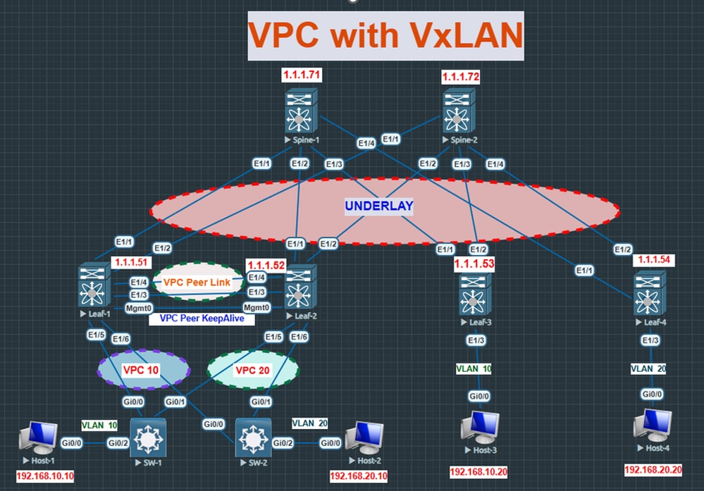
For this lab, the EveNg with Nexus 9000V switches is utilized for both the Leaf and Spine.
|
Virtual Tunnel Endpoint (VTEP)
|
LEAF1, LEAF2, LEAF3, LEAF4
|
|
vPC
|
LEAF1 and LEAF2
|
|
LEAF1 Primary and Secondary loopback IP
|
Loopback0 – 1.1.1.51, Loopback1 - 10.1.1.100
|
|
LEAF2 Primary and Secondary loopback IP
|
Loopback0 – 1.1.1.52, Loopback1 - 10.1.1.100
|
|
LEAF3 loopback IP
|
1.1.1.53
|
|
LEAF4 loopback IP
|
1.1.1.54
|
|
SPINE1 loopback and Anycast RP
|
Loopback0 - 1.1.1.71, Loopback1 - 10.1.2.10 (Anycast RP)
|
|
SPINE2 loopback and Anycast RP
|
Loopback0 - 1.1.1.72, Loopback1 - 10.1.2.10 (Anycast RP)
|
|
HOST 1
|
192.168.10.10 (0000. 0000.aaaa) (VLAN 10)
|
|
HOST 2
|
192.168.20.10 (0000. 0000.bbbb) (VLAN 20)
|
|
HOST 3
|
192.168.10.20 (0000. 0000.cccc) (VLAN 10)
|
|
HOST 4
|
192.168.20.20 (0000. 0000.dddd) (VLAN 20)
|
|
VLAN 10
|
L2VNI 100010
|
|
VLAN 20
|
L2VNI 100020
|
|
VLAN 500
|
L3VNI 50000
|
Configure
Network Diagram
Configurations
- Underlay and PIM neighborships are already established.
LEAF Switch:
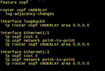
Enabling Open Shortest Path First (OSPF) on Leaf Switch
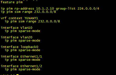
Enabling PIM on Leaf Switch
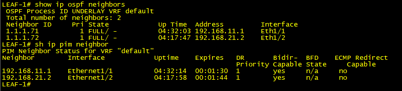
OSPF Neighbor
Spine Switch:
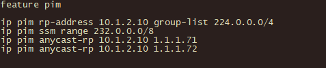
Enabling PIM on Spine Switch
- Underlay and PIM neighborships are already established.
- Both Spine switches will be the identical Anycast RP for the whole multicast group 224.0.0.0/4.
- Maximum Transmission Unit (MTU) is set to 9000/9216 on the interfaces between the Leaf and Spine switches.
First, lets set up a vPC between Leaf1 and Leaf2.
Step 1. vPC feature and domain enablement.
- Enable feature vPC and Link Aggregation Control Protocol (LACP).
- Configure the vPC domain.
- The mgmt 0 interfaces are used as a peer keepalive link and Eth1/3 and Eth1/4 will be the part of vPC peer link (Port-Channel 1).
- Ensure that the peer-switch command is configured to share a common MAC address with descending switches.
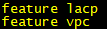
Enabling Feature on Leaf Switch
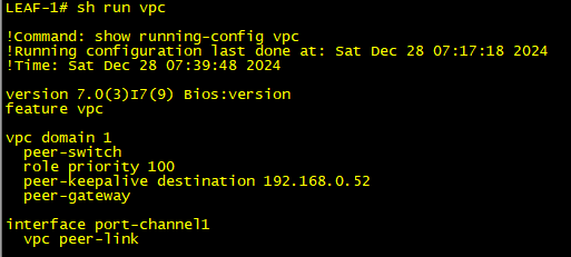
Enabling vPC on Leaf Switch 1
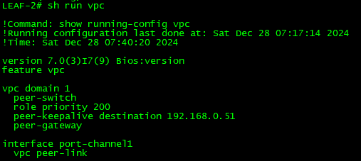
Enabling vPC on Leaf Switch 2
Step 2. Port member assignment.
- Assign the port member to the channel group and include them in the vPC. In this case, two vPCs are being used. vPC 20 and vPC 10.
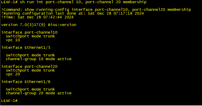
Assigning Port Channel on Leaf Switch 1
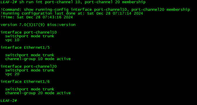
Assigning Port Channel on Leaf Switch 2
- Here, a vPC is created, and peers begin exchanging keepalive messages in order to verify availability.
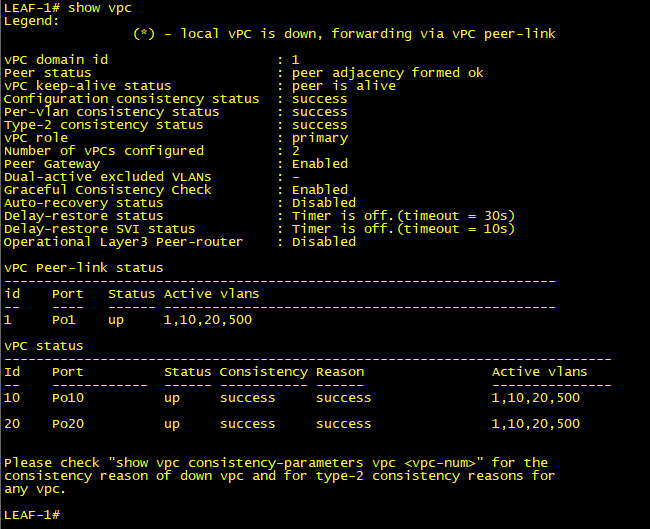
vPC Status on Leaf Switch 1
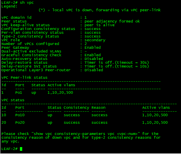
vPC Status on Leaf Switch 2
- VLAN 10, 20, 500 is already configured and passed over the vPC member ports and vPC peer link.
Step 3. Configure the Secondary IP address.
- When vPC is included in the VXLAN fabric, both vPC VTEP peers start using virtual IP (VIP) addresses as source addresses instead of their physical IP addresses (PIP). This also means that when BGP Ethernet VPN (EVPN) advertises Route Types 2 (MAC/IP advertisement) and 5 (IP prefix-route) by default, VIP is used as a next-hop. The Loopback 0 interface in our example is set up with two IP addresses: 10.1.1.100/32 (VIP) as the secondary IP and 1.1.1.51/32 (PIP) as the primary IP.
- Here a common IP address is configured as a secondary one under the loopback 0 interface.
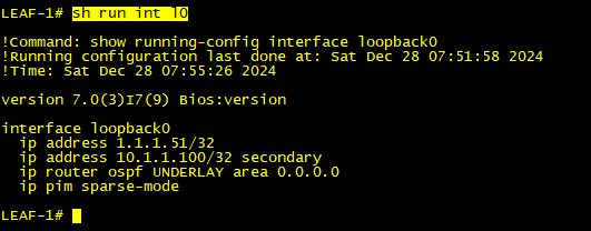
Secondary IP on Leaf Switch 1
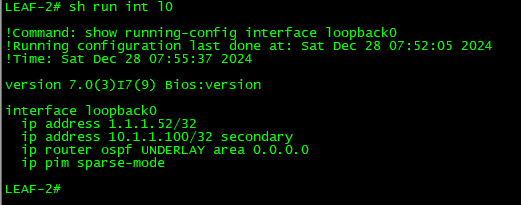
Secondary IP on Leaf Switch 2
Step 4. Enable VXLAN and related features.
- Network Virtualization (nV) overlay - enables VXLAN
- Feature nV overlay EVPN- enables EVPN Control Plane
- Feature fabric forwarding - enables Host Mobility Manager
- Feature Virtual Network (VN)-segment-VLAN-based - enables VLAN-based VXLAN
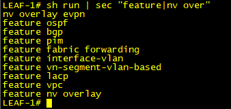
Features on Leaf Switch
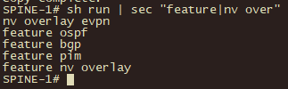
Features on Spine Switch
- Since the spine does not require knowledge of the VLAN information of the client, the VN-segment and fabric features does not need to be enabled.
Step 5. Bring up the BGP neighborship.
- BGP between the Leaf and Spine switches must be enabled. The spine will serve as a route reflector in the lab.
- Although, it is optional to configure Route Reflector (RR), for the sake of scalability, Cisco recommends RR.
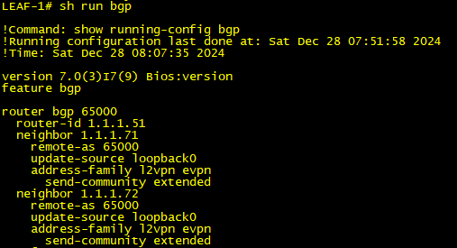
Enabling BGP on Leaf Switch
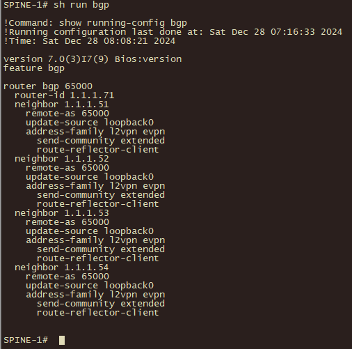
Enabling BGP on Spine Switch
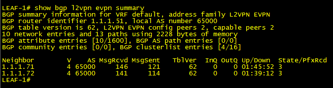
BGP Status on Leaf Switch
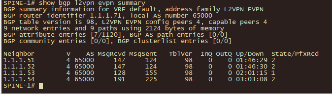
BGP Status on Spine Switch
Step 6. Enable VRF context on leaf switches. VRF separates customer traffic and facilitates communication between two distinct L2VNIs via L3VNI.
- Allocate L3VNI 50000 under VRF TENANT1.
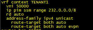
L3VNI Allocation
Step 7. Network Virtual Interface (NVE), VXLAN identifier (VNI), and VLAN configuration.
- Set up the NVE Interface, using Loopback 0 as the source. Define the Multicast group for each VNI, where Layer 2 Broadcast, Unknown unicast, and Multicast (BUM) traffic will be delivered, then attach the VNI 100010 and 100020 IDs to the NVE interface. The VXLAN header contains the information that the VNI uses in order to identify which VXLAN segments it belongs to.
- The L3VNI 50000 is linked to the VRF instance (when sending it to the spine switch, VNI 50000 was attached in the VRF table).
- The host-reachability protocol BGP command activates the EVPN address family in the VXLAN tunnel, which means that MAC addresses and IP addresses are learned via the BGP protocol in the control plane and not in the data plane.
- Configure suppress-arp under the NVE interface.
- Attach Layer 2 and Layer 3 VLAN to relevant VNI.
Suppress-Address Resolution Protocol (ARP):
The Multi-Protocol (MP)-BGP EVPN control plane offers an improvement called ARP suppression in order to lessen network flooding brought on by broadcast traffic from ARP requests. Each of a VNIs VTEPs keeps an ARP suppression cache table for known IP hosts and the MAC addresses that correspond to them in the VNI segment when ARP suppression is enabled for that VNI. Its local VTEP intercepts the ARP request and looks for the ARP-resolved IP address in its ARP suppression cache table whenever an end host in the VNI submits an ARP request for another end-host IP address. On behalf of the remote end host, the local VTEP sends an ARP response if it discovers a match. The ARP response then provides the local host with the remote hosts MAC address. The ARP request is flooded to the other VTEPs in the VNI if the local VTEP does not have the ARP-resolved IP address in its ARP suppression table. For the first ARP request to a silent network host, this ARP flooding can take place.
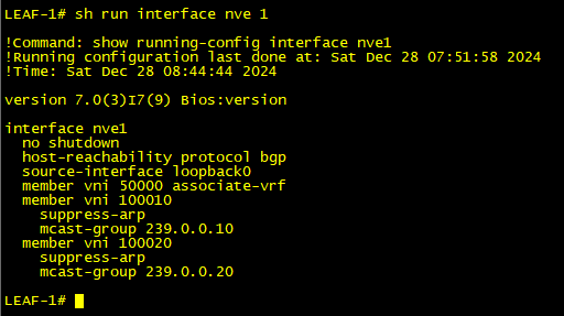
NVE Interface
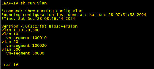
VLAN to VN-Segment Mapping
- By sending Spine a PIM join message, the NVE interface will join the multicast groups 239.0.0.10 and 239.0.0.20, respectively, as soon as it boots up.
- You can see other (S, G) tables as well (1.1.1.54,239.0.0.20) and (10.1.1.100, 239.0.0.10/239.0.0.20) in the image and those are already registered with Spine from different Leaf Switches.
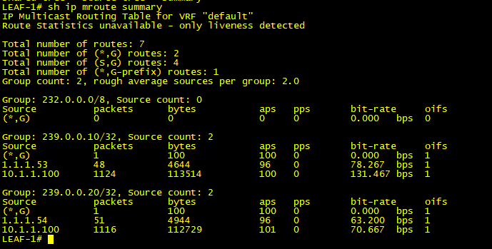
Mroute Table
Step 8. Enable EVPN instance.
- Enable EVPN instance along with address-family for EVPN and VRF under BGP.
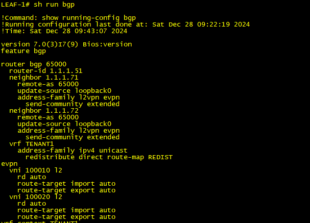
EVPN Instance
- The only purpose of route-map REDIST is to allow everything.
- Using the redistribute direct command, the connected VRF-aware routes are promoted into MP-BGP (type 5 routes).
- The EVPN configuration displayed above is identical to the network statement used by BGP in order to advertise MAC routes (type 2 routes).
Step 9. Configure Switch Virtual Interface (SVI) for each VLAN for the end host under VRF.
- On each leaf switch, the SVI is configured for locally configured VLAN and one SVI for L3VNI VLAN in order to achieve the Symmetric Routing Information Base (RIB).
Symmetric RIB:
- When the End host sends the data packet to a different network and it receives to the Leaf Switch, it will be processed into L2VNI first and then it will be placed to L3VNI using VRF and sent to the remote Leaf.
- Remote Leaf first receives the packets in the VRF table using Routing and then bridging to L2VNI and sends it to the end host.
- By that way, the Symmetric Routing (B-R-R-B) is achieved.
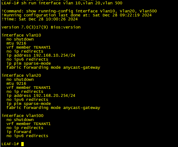
VLAN Interfaces
- The IP forward command under the VLAN 500 is used to enable Layer 3 forwarding for all VXLANs. There is no need to configure IP address, as it just processes the packet from the L2VNI table to the L3VNI table.
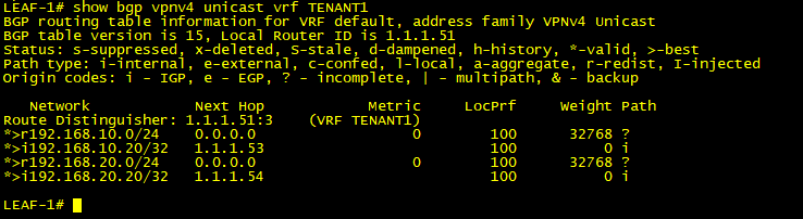
Learning BGP VPNv4 Routes for VRF TENANT1
- The IP address for each VLAN will be common for all the SVIs on all leaf switches. This is called anycast IP and it is used in Mobility Management where the end can communicate to another host seamlessly without any disruption.
Step 10. Enable fabric forwarding anycast gateway MAC for the end host.
- It ensures seamless Layer 3 gateway redundancy and optimized forwarding for devices connected to the fabric.
- The Anycast Gateway MAC address is a globally consistent MAC address used for all Layer 3 gateways in a fabric.
- The concept is identical to that which is employed in First Hop Redundancy Protocol (FHRP), where each group is issued a virtual MAC.
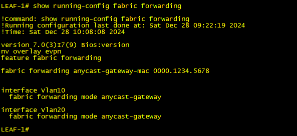
Enabling Fabric Forwarding
Step 11. Enable the Access/Trunk VLAN to the member ports.
vPC Switch:
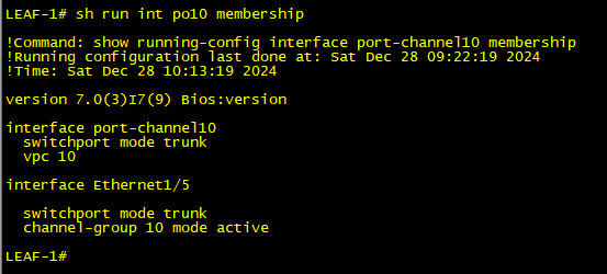
Enabling Trunk Ports to the vPC Member Interface
Non-vPC Switch:
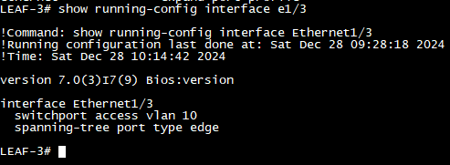
Enabling Trunk Ports to the Non vPC Member Interface
Verification
- Check the ARP and MAC address table.
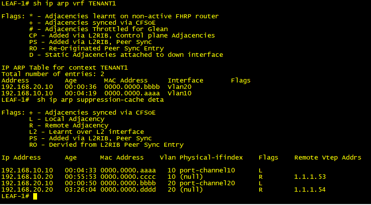
ARP and MAC Table on LEAF Switch 1
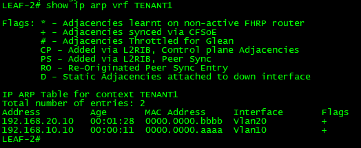
ARP and MAC Table on LEAF Switch 2
- Both peers maintain the ARP entries.
- Check the Network Virtual Interface (NVI) status.
vPC Switch:
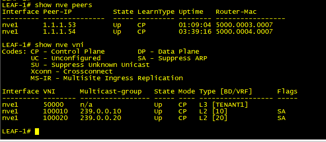
NVE Peers on vPC Switch
Non-vPC Switch:
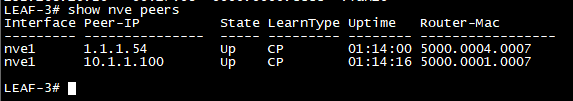
NVE Peers on Non vPC Switch
- Here, you will notice that the peer IP is 10.1.1.100 instead of the primary loopback IP address, so the return packet will be routed for that IP to any of the vPC switches.
- Check BGP EVPN routes.
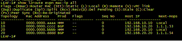
BGP l2route EVPN MAC-IP
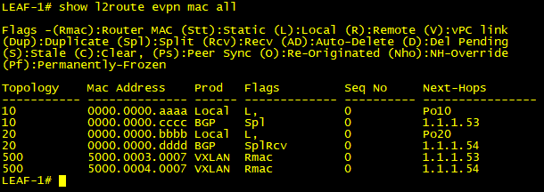
BGP l2route EVPN MAC
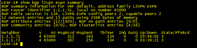
BGP EVPN Summary
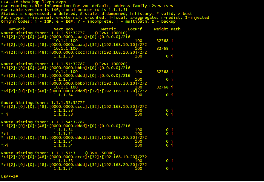
BGP EVPN Routes
-
It is common to question how Leaf Switches acquire MAC entries for remote hosts. This process is facilitated by Gratuitous ARP. When a network port is activated, it immediately sends an ARP request in order to verify the uniqueness of the IP address. Each Leaf Switch then records the MAC address and includes it in a BGP Update Packet. This allows other Leaf Switches to update their respective MAC address tables accordingly. But there can be a case where the end host does not generate Gratuitous ARP (Silent host), and in that case, the ARP request will be broadcast to the leaf and as it is a broadcast request, the Leaf switch will generate the multicast request to the respective group for the particular VNI. In this case, it is 239.0.0.10 and 239.0.0.20.
- Lets ping from Host-1 to Host-3 within the same VNI and look at the capture.
Pinging from HOST-1 to HOST-3
Internet Control Message Protocol (ICMP) Packet over the VXLAN:
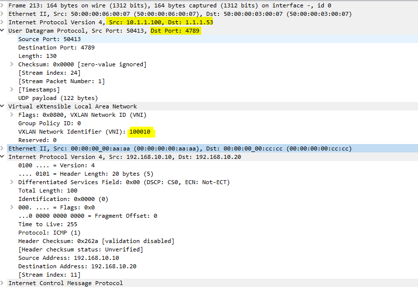
Wireshark Capture Showing ICMP Request Packet Travelling Through L2VNI 10010
- As you can see, the source IP is 10.1.1.100 with port 4789 as the UDP destination.
- Since it is an intra-VNI communication, VLAN 10 will use VNI 100010, and VLAN 20 will use VNI 1000.
- Lets ping from Host-1 to Host-4 with different VNI and look at the capture.
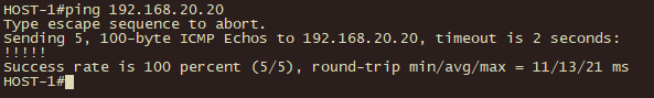
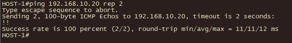
Pinging from HOST-1 to HOST-4
ICMP Packet over the VXLAN:
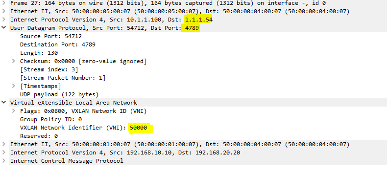
Wireshark Capture Showing ICMP Request Packet Travelling Through L3VNI 50000
- Since it is an inter-VNI communication, the L3VNI 50000 will be used.
- Check the ARP table for end host.
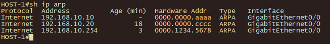
HOST-1 ARP Entries
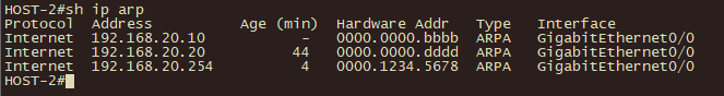
HOST-2 ARP Entries
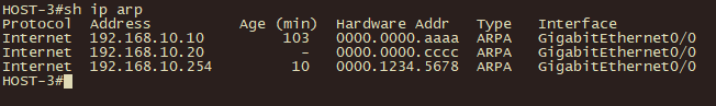
HOST-3 ARP Entries

HOST-4 ARP Entries
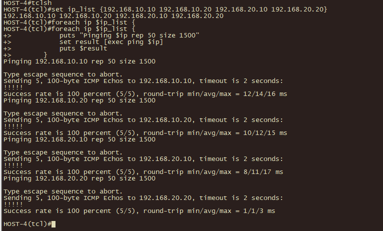
Pinging from HOST-4 to All Other End Hosts
 Feedback