Configure Onboard Packet Capture in Catalyst 1200 and 1300 Switches using Web User Interface
Available Languages
Objective
The objective of this article is to show how to configure onboard packet capture (OPC) in Catalyst 1200 and 1300 switches using the web user interface (UI).
Applicable Devices | Software Version
- Catalyst 1200 Switches | 4.1.6.53
- Catalyst 1300 Switches | 4.1.6.53
Introduction
The OPC feature enhances troubleshooting capabilities on the device. When enabled, OPC will allocate up to a maximum of 20MB of memory for capturing packet data. This feature requires the configuration of a capture point that defines the behavior of an OPC instance. The capture point is used to define all the settings associated with an OPC instance.
A maximum of 4 capture points can be configured on a switch, however only one capture point may be active at a time. The data captured in memory can be saved to either the onboard flash if there is free space, or to an attached USB device like a USB flash drive. As OPC may consume considerable CPU resources, it is recommended to use it only as needed.
To configure this feature using the command line interface (CLI), refer to the article Configure Onboard Packet Capture in Catalyst 1200 and 1300 Switches using CLI.
Table of Contents
Configure OPC
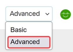
Step 1
Login to the Catalyst 1200 or 1300 switch and select Advanced mode from the drop-down menu.
Step 2
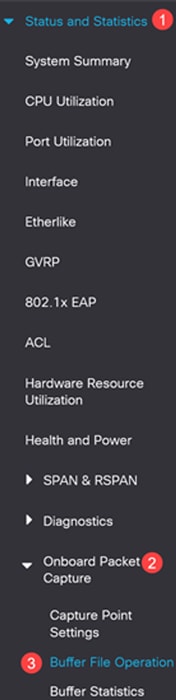
Navigate to Status and Statistics > Onboard Packet Capture > Capture Point Settings.
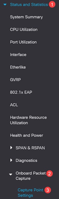
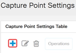
Step 3
Click Add to add a capture point.
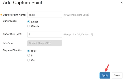
Step 4
Configure the following capture point settings.
- Capture point name
- Buffer Mode - Define the capture mode to one of the following:
- Linear - capture will be terminated when the capture buffer is full.
- Circular - the capture wraps up when the buffer is full and rewrite the packets in the beginning of the buffer.
- Buffer Size: Define the size of the capture buffer in MB. The buffers for all capture points cannot exceed 20MB.
- Interface - only the Control Plane (CPU) interface is supported.
- Capture Direction - define the direction of the traffic to capture: both inbound and outbound traffic (both), only inbound traffic (in) or only outbound traffic (out).
Click Apply.
Step 5
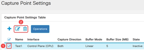
To edit or delete a capture point, select the capture point and click Edit or Delete.
Starting and Stopping the Capture
Step 1
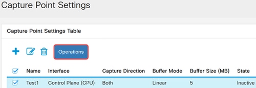
To activate a capture point, select the desired capture point from the table and click the Operations button.
Step 2
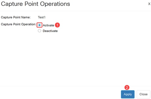
In the Capture Point Operation window select Activate and click Apply. The state of the capture point in the Capture Point Settings Table is set to Active.
Step 3
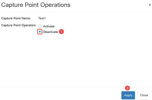
To deactivate an active capture point, select an active capture point and click Operations. Under the Capture Point Operation field, select Deactivate and click Apply. The state of the capture point in the Capture Point Settings Table is set to Inactive.
Buffer File Operation
The captured packets are stored in a memory buffer. To copy the packets to a nonvolatile memory for further debugging perform the following steps:
Step 1
Navigate to Status and Statistics > Onboard Packet Capture > Buffer File Operation.
Step 2
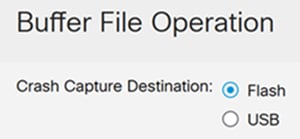
If the device crashes during a capture, the packets are saved automatically to a nonvolatile memory. Select the destination device for saving the crash report.
- Flash - to save the file to the device flash (Default)
- USB - to save the file to a USB storage device connected to the switch
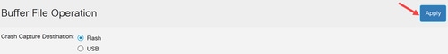
Step 3
Click Apply to save the configuration for the Crash Capture Destination.
Step 4
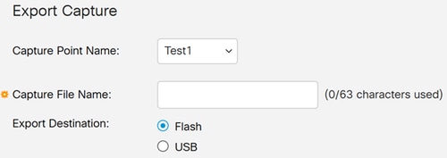
To manually export one of the capture point buffers, navigate to the Export Capture section and configure the following:
- Capture Point Name - Select the capture point that you want to export.
- Capture File Name - Define a name for the exported file.
- Export Destination - Select the destination device for saving the file:
- Flash – do save the file to the device flash.
- USB – to save the device to a USB storage device connected to the device.
Step 5
To export the Capture Point file, click Export.

Buffer Statistics
The Buffer Statistics page displays information relating to a specific Capture Point. To view the capture buffer statistics, complete the following steps.
Step 1
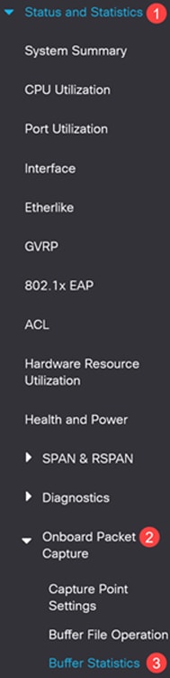
Navigate to Status and Statistics > Onboard Packet Capture > Buffer Statistics.
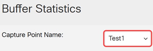
Step 2
In the Capture Point Name field, select the capture buffer from the drop-down list to view the statistics.
Step 3
Select the Refresh Rate from the following options:
- No Refresh
- 15 sec
- 30 sec
- 60 sec
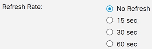
Refresh rate will not have any impact if the selected capture point is not active.
Step 4
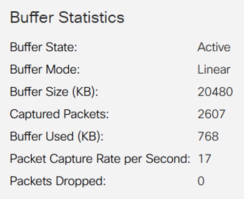
The following statistics will be displayed:
- Buffer State - Active or Inactive
- Buffer Mode - Linear or circular
- Buffer Size (KB) - The size of the buffer in Kilobytes
- Captured Packets - The number of the packet captures
- Buffer Used (KB) - The actual buffer size that is used
- Packet Capture Rate per Second - The packet per second rate of the traffic that was captured.
- Packets Dropped - The number of packets that were dropped during the capture session.
Step 5
To manually refresh the information, click Refresh.

Step 6
To clear the buffer, click Clear Buffer.

Conclusion
It’s as simple as that. Now you know all about configuring and using OPC in Catalyst 1200 and 1300 switches.
For more information, check out the Catalyst 1200 Admin Guide and Catalyst 1300 Admin Guide.
Looking for more articles on your Catalyst 1200 and1300 switch? Go through the product support link below for more information!
Revision History
| Revision | Publish Date | Comments |
|---|---|---|
1.0 |
17-Feb-2025
|
Initial Release |
 Feedback
Contact Cisco
- Open a Support Case

- (Requires a Cisco Service Contract)