Introduction
This document describes how to configure jumbo Maximum Transition Unit (MTU) end-to-end across Cisco Data Center devices.
Prerequisites
Requirements
Cisco recommends that you have knowledge of these topics:
- VMware ESXi
- Cisco UCS
- Cisco N5k
- Cisco Internet Small Computer Systems Interface (iSCSI)
Components Used
This document describes how to configure jumbo Maximum Transition Unit (MTU) end-to-end across Cisco Data Center devices in a network that consists of a VMware ESXi host installed on the Cisco Unified Computing System (UCS), Cisco Nexus 1000V Series Switches (N1kV), Cisco Nexus 5000 Series Switches (N5k), and the Cisco NetApp controller.
The information in this document is based on these software and hardware versions:
- Cisco Nexus 5020 Series Switches Version 5.0(3)N2(2a)
- Cisco UCS Version 2.1(1d)
- Cisco UCS B200 M3 Blade Server with Cisco Virtual Interface Card (VIC) 1240
- vSphere 5.0 (ESXi and vCenter)
- Cisco N1kV Version 4.2(1)SV2(2.1a)
- NetApp FAS 3240
The information in this document was created from the devices in a specific lab environment. All of the devices used in this document started with a cleared (default) configuration. If your network is live, ensure that you understand the potential impact of any command.
Configure
Network Diagram
The typical iSCSI Storage Area Network (SAN) deployment uses the Cisco UCS with a Fabric Interconnect in Ethernet End Host mode and the storage target connected through an upstream switch or switched network.
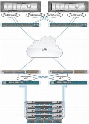
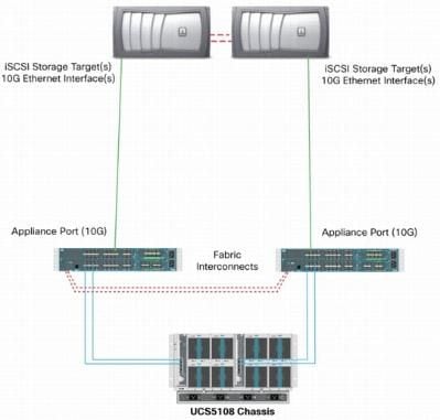
Through the use of the Appliance ports on the UCS, Storage can be directly connected to the Fabric Interconnects.
Whether the upstream network is 1 GbE or 10 GbE, the use of jumbo frames (an MTU size of 9000, for example) improves performance because it reduces the number of individual frames that must be sent for a given amount of data and reduces the need to separate iSCSI data blocks into multiple Ethernet frames. They also lower the host and storage CPU utilization.
If jumbo frames are used, ensure that the UCS and storage target, as well as all of the network equipment between, are able and configured in order to support the larger frame size.
This means that the jumbo MTU must be configured end-to-end (initiator to target) in order for it to be effective across the domain.
Here is an overview of the procedure that is used in order to configure the jumbo MTU end-to-end:
- Create a UCS Quality of Service (QoS) System Class with an MTU of 9000, and then configure the Virtual NIC (vNIC) with jumbo MTU.
- Enable jumbo frames (MTU 9000) on all of the switches between the initiator (UCS) and the iSCSI target.
- Enable jumbo frames on the Operating System (OS) adapter (VMkernel port of the ESXi).
- Enable jumbo frames on the NetApp interfaces.
Note: Reference the Cisco Unified Computing System (UCS) Storage Connectivity Options and Best Practices with NetApp Storage Cisco article for additional information.
Cisco UCS Configuration
The MTU is set on a per-Class of Service (CoS) basis within the UCS. If you do not have a QoS policy defined for the vNIC that heads toward the vSwitch, then the traffic moves to the Best-Effort Class.
Complete these steps in order to enable jumbo frames:
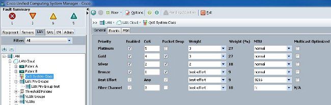
- From the UCS GUI, click the LAN tab.
- Navigate to LAN > LAN Cloud > QoS System Class.
- Click the QoS System Class and change the traffic class (that carries iSCSI traffic) MTU to 9216.
Note: This example uses the Best Effort traffic class in order to illustrate this MTU update.
- Create a QoS policy within the LAN tab and apply it to the vNIC that carries the storage traffic.
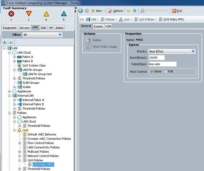
- Navigate to the vNIC template or the actual vNIC under the Service Profiles and set the MTU value to 9000.
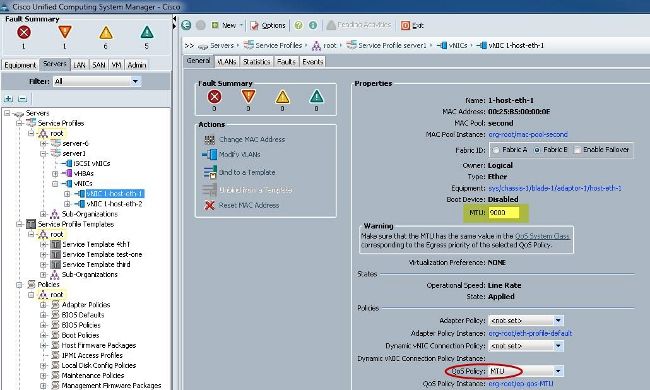
Verify
Verify that the vNIC has the MTU configured as previously described.
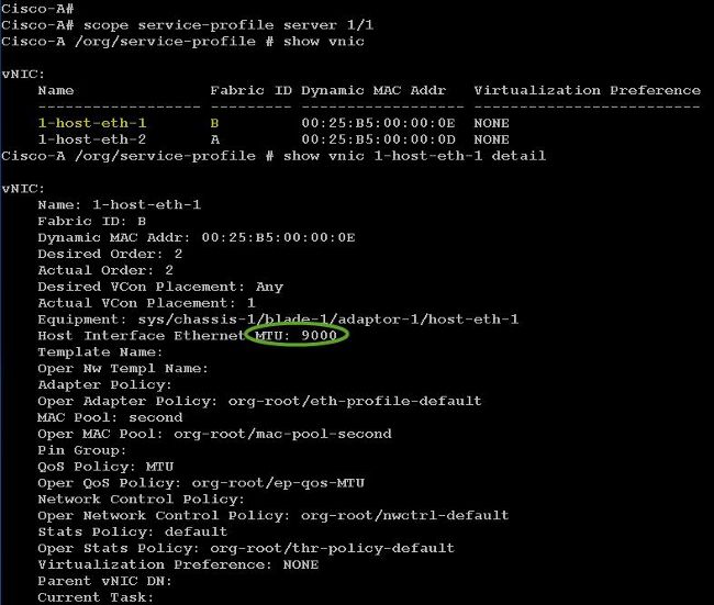
Verify that the uplink ports have jumbo MTU enabled.
N5k Configuration
With the N5k, jumbo MTU is enabled at the system level.
Open a command prompt and enter these commands in order to configure the system for jumbo MTU:
switch(config)#policy-map type network-qos jumbo
switch(config-pmap-nq)#class type network-qos class-default
switch(config-pmap-c-nq)#mtu 9216
switch(config-pmap-c-nq)#exit
switch(config-pmap-nq)#exit
switch(config)#system qos
switch(config-sys-qos)#service-policy type network-qos jumbo
Verify
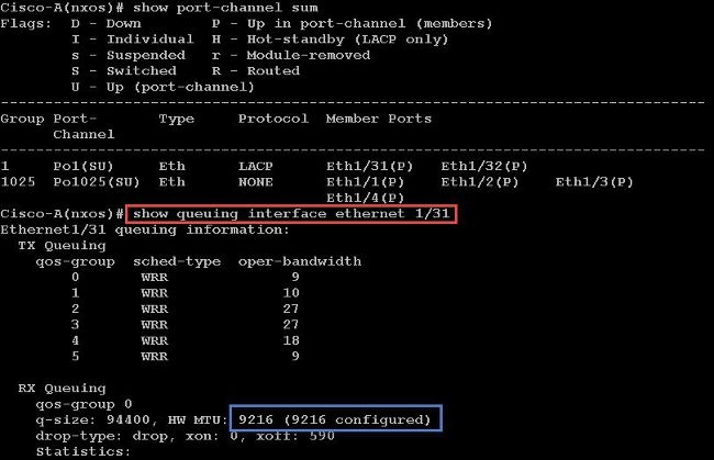
Enter the show queuing interface Ethernet x/y command in order to verify that jumbo MTU is enabled:
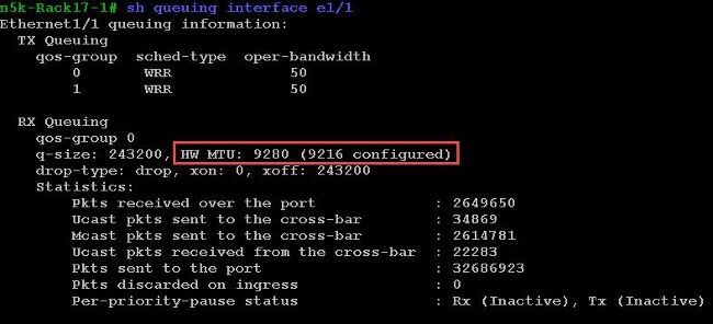
Note: The show interface Ethernet x/y command shows an MTU of 1500, but that is incorrect.
VMware ESXi Configuration
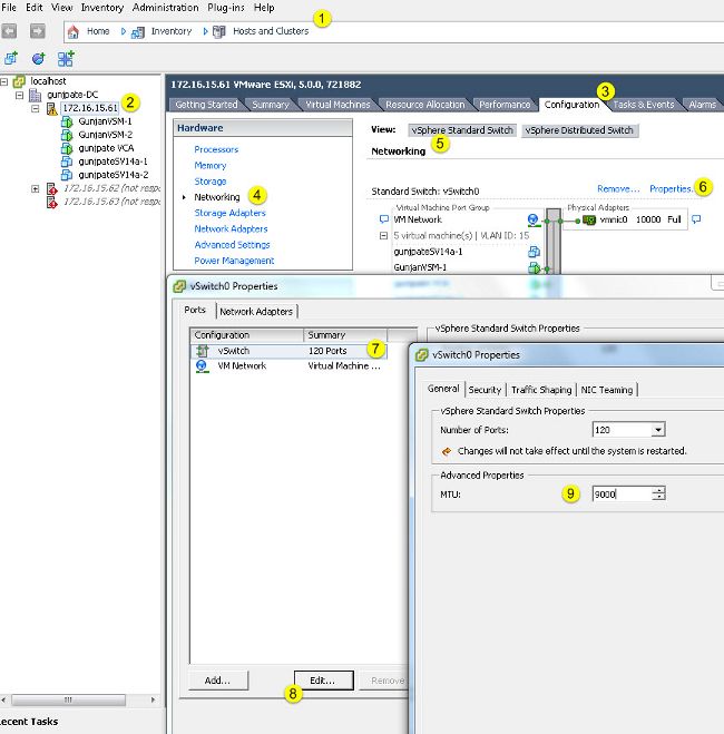
You can configure the MTU value of a vSwitch so that all of the port-groups and ports use jumbo frames.
Complete these steps in order to enable jumbo frames on a host vSwitch:
- Navigate to Home > Inventory > Hosts and Clusters from the vSphere client.
- Select the host.
- Click the Configuration tab.
- Select Networking in the Hardware menu.
- Choose vSphere Standard Switch in the View field.
- Click Properties.
- Select vSwitch on the Ports tab of the Properties pop-up window.
- Click Edit.
- On the General tab of the pop-up window, change the MTU (under Advanced Properties) from the default value (1500) to 9000. This enables jumbo frames on all of the port-groups and ports of the vSwitch.
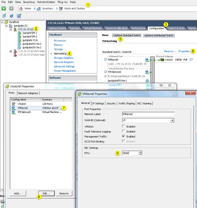
Complete these steps in order to enable jumbo frames only on a VMkernel port from the vCenter server:
- From the vSphere client, navigate to Home > Inventory > Hosts and Clusters.
- Select the host.
- Click the Configuration tab.
- Select Networking in the Hardware menu.
- Choose vSphere Standard Switch in the View field.
- Click Properties.
- Select VMkernel on the Ports tab of the Properties pop-up window.
- Click Edit.
- On the General tab of the pop-up window, change the MTU (under NIC Settings) from the default value (1500) to 9000. This enables jumbo frames on only a VMkernel port of the vSwitch.
Verify
Enter the vmkping -d –s 8972 <storage appliance ip address> command in order to test the network connectivity and verify that the VMkernel port can ping with jumbo MTU.
Tip: Reference the Testing VMkernel network connectivity with the vmkping command VMware article for more information about this command.
Note: The largest true packet size is 8972, which sends a 9000-byte packet when you add the IP and ICMP header bytes.
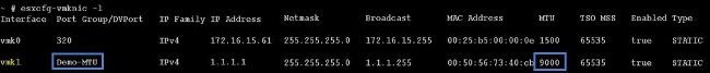
At the ESXi host level, verify that the MTU settings are configured properly:
Cisco IOS Configuration
With Cisco IOS® switches, there is no concept of global MTU at the switch level. Instead, MTU is configured at the interface/ether-channel level.
Enter these commands in order to configure jumbo MTU:
7609(config)#int gigabitEthernet 1/1
7609(config-if)#mtu ?
<1500-9216>  MTU size in bytes
7609(config-if)#mtu 9216
Verify
Enter the show interfaces gigabitEthernet 1/1 command in order to verify that the configuration is correct:
7609#show interfaces gigabitEthernet 1/1

GigabitEthernet1/1 is up, line protocol is up (connected)
  Hardware is C6k 1000Mb 802.3, address is 0007.0d0e.640a (bia 0007.0d0e.640a)
  MTU 9216 bytes, BW 1000000 Kbit, DLY 10 usec,
  reliability 255/255, txload 1/255, rxload 1/255
N1kV Configuration
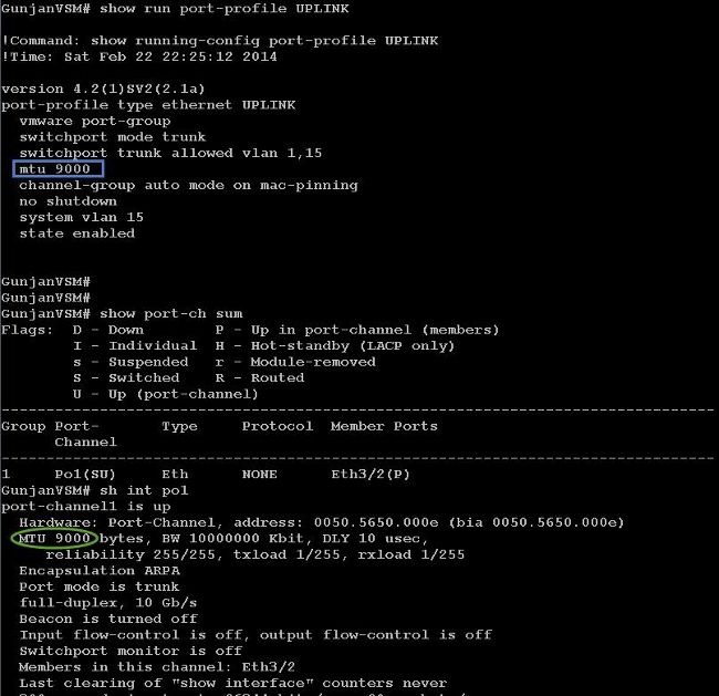
With the N1kV, the jumbo MTU can only be configured on the Ethernet port-profiles for uplink; MTU cannot be configured at the vEthernet interface.
Verify
Enter the show run port-profile UPLINK command in order to verify that the configuration is correct:
NetApp FAS 3240 Configuration
On the storage controller, the network ports that are connected to the Fabric Interconnect or to the Layer 2 (L2) switch must have jumbo MTU configured. Here is an example configuration:
FAS3240-A> vlan create e1a 100
Ethernet e1a: Link being reconfigured.
vlan: e1a-100 has been created
Ethernet e1a: Link up.

FAS3240-A> vlan create e1b 100
Ethernet e1b: Link being reconfigured.
vlan: e1b-100 has been created
Ethernet e1b: Link up.

FAS3240-A> ifconfig e1a-100 192.168.101.105 netmask 255.255.255.0 mtusize 9000
partner e1a-100

FAS3240-A> ifconfig e1b-100 192.168.102.105 netmask 255.255.255.0 mtusize 9000
partner e1b-100
Verify
Use this section in order to verify that the configuration is correct.
FAS3240-A> ifconfig –a
e1a: flags=0x80f0c867<BROADCAST,RUNNING,MULTICAST,TCPCKSUM,VLAN> mtu 9000
 ether 00:c0:dd:11:40:2c (auto-10g_twinax-fd-up) flowcontrol full
e1b: flags=0x80f0c867<BROADCAST,RUNNING,MULTICAST,TCPCKSUM,VLAN> mtu 9000
 ether 00:c0:dd:11:40:2e (auto-10g_twinax-fd-up) flowcontrol full
 Feedback