Troubleshoot Multicast on C9800 Wireless LAN Controller
Available Languages
Download Options
Bias-Free Language
The documentation set for this product strives to use bias-free language. For the purposes of this documentation set, bias-free is defined as language that does not imply discrimination based on age, disability, gender, racial identity, ethnic identity, sexual orientation, socioeconomic status, and intersectionality. Exceptions may be present in the documentation due to language that is hardcoded in the user interfaces of the product software, language used based on RFP documentation, or language that is used by a referenced third-party product. Learn more about how Cisco is using Inclusive Language.
Contents
Introduction
This document describes the multicast workflow, configuration, and troubleshooting on the Cisco C9800 Wireless LAN Controller.
Prerequisites
Requirements
- Cisco recommends that you have knowledge of these topics:
- Multicast concepts
- 9800 Wireless LAN Controller(WLC) configuration
Components Used
The information in this document is based on these software and hardware versions:
- Catalyst 9800 Wireless Controller Series (Catalyst 9800-40), Cisco IOS® XE Cupertino 17.12.5
- Catalyst 3560 Series Switch, Cisco IOS® 15.2.4E10
- Access Point C9115AXE, Access Point CW9164I
The information in this document was created from the devices in a specific lab environment. All of the devices used in this document started with a cleared (default) configuration. If your network is live, ensure that you understand the potential impact of any command.
Background Information
Multicast is a protocol that sends packets from a single source to a group-based destination address. Only hosts that have expressed interest in receiving the packets receive them.
Internet Group Management Protocol Overview
Internet Group Management Protocol (IGMP) is used to dynamically register individual hosts as members of a multicast group on a specific LAN.
IGMP Snooping is a process by which a switch listens to IGMP network traffic between hosts and routers to build and maintain a table of client MAC addresses that ate interested in receiving specific multicast streams. By snooping on IGMP packets, the switch can manage multicast traffic efficiently and prevent unnecessary flooding. Without IGMP Snooping, multicast traffic is treated similarly to broadcast traffic, reaching all devices on the segment.
IGMP Message Types:
- Membership Query:
Sent by a router or a switch with IGMP Snooping enabled to determine if there are any interested receivers for a specific multicast group. Queries can be general, group-specific, or group-and-source-specific (the latter is used in IGMPv3) - Membership Report:
Sent by a host to indicate interest in joining a multicast group or in response to a membership query. This message type is also known as an IGMP Join - Leave Group Message:
Sent by a host when it no longer wishes to receive multicast traffic for a particular group.
IGMP Versions:
- IGMPv1: Uses a basic query-response model, allowing multicast routers and multilayer switches to determine which multicast groups have active members on a subnet. Hosts can join or leave groups as specified in RFC 1112.
- IGMPv2: Enhances functionality by introducing the leave process (reducing leave latency), group-specific queries, and explicit maximum query response time. It also allows routers to elect an IGMP querier independently of the multicast protocol. For more details, refer to RFC 2236.
- IGMPv3: Adds support for Source-Specific-Multicast (SSM), enabling hosts to specify the sources from which they want to receive multicast traffic for a group. IGMPv3 uses the multicast address 224.0.0.22 for membership reports and includes detailed "Group Records" to convey source information. For more details, refer to RFC 3376.
Multicast Modes on WLC
- Unicast mode: The controller unicasts every multicast packet to every access point associated to the controller. This mode is inefficient and generates a lot of extra traffic in the device and the network but is required on networks that do not support multicast routing (needed if the APs are on different subnets than the Wireless Management Interface(WMI) of the device).
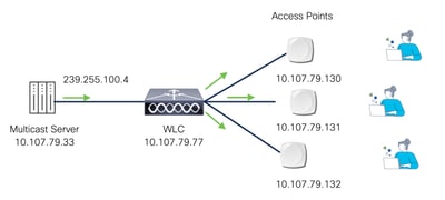 Multicast-over-Unicast
- Multicast mode: The controller sends multicast packets to a CAPWAP multicast group. This method reduces the overhead on the controller processor and shifts the work of packet replication to the network, which is much more efficient than the unicast method.
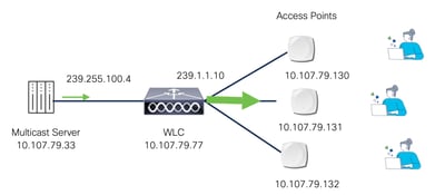 Multicast-over-Multicast
To receive multicast traffic, Access Points (APs) send an IGMP Join membership report to the configured Multicast CAPWAP Group address. This allows the APs to join the multicast group and start receiving the associated multicast traffic.
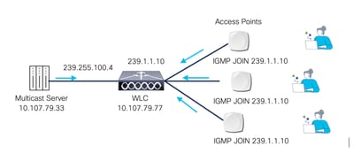 AP IGMP Join
Multicast Traffic Handling by WLC
A single CAPWAP multicast group address is used to deliver multicast traffic across WLANs. To manage this, the controller maintains a Layer 2 table that maps its interfaces to WLANs using unique multicast group IDs (MGIDs), identifying where multicast traffic must be sent. An MGID is a 14-bit value placed in the 16-bit reserved field of the CAPWAP header, with the remaining 2 bits set to zero.
Not all clients on a WLAN need the same multicast traffic. To identify interested clients, IGMP snooping enables access points to listen for IGMP membership reports from hosts. Based on this, the controller builds a Layer 3 multicast group table. Each entry includes the MGID, CAPWAP multicast group address, and VLAN ID. It also lists specific clients that joined the group and the APs they are associated with.
When the multicast mode is enabled and the controller receives a multicast packet from the wired LAN, the controller encapsulates the packet using CAPWAP and forwards the packet to the CAPWAP multicast group address. The controller always uses the management VLAN for sending multicast packets. Access points in the multicast group receive the packet and forward it to all the BSSIDs mapped to the VLAN on which clients receive multicast traffic.
Multicast Support Per Platform
Table 1. Multicast Support Per Platform
|
Platform |
MulticastSupport -Multicastover Unicast |
MulticastSupport -MulticastoverMulticast |
|---|---|---|
|
Cisco Catalyst 9800-40 Wireless Controller |
No |
Yes |
|
Cisco Catalyst 9800-80 Wireless Controller |
No |
Yes |
|
Cisco Catalyst 9800 Wireless Controller for Cloud- Small Template |
Yes |
Yes |
|
Cisco Catalyst 9800 Wireless Controller for Cloud- Medium Template |
No |
Yes |
|
Cisco Catalyst 9800 Wireless Controller for Cloud- Large Template |
No |
Yes |
|
Cisco Catalyst 9800-L Wireless Controller |
Yes |
Yes |
Configure
Network Diagram
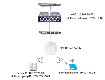 Network Diagram
Configurations
To configure multicast from the WLC GUI, go to Configuration > Services > Multicast. Enable Global Wireless Multicast Mode, select AP CAPWAP Multicast as Multicast, enter the CAPWAP multicast group address, and click Apply. Use an address from the 239.0.0.0/8 subnet and ensure it is unique within the network.
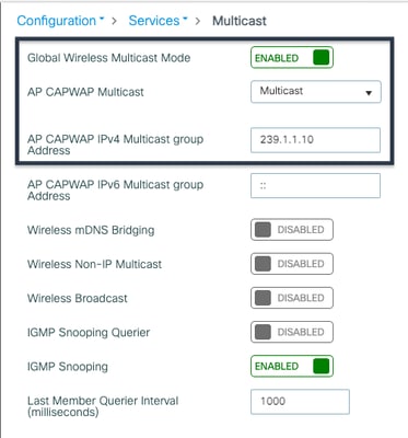 Multicast GUI Configuration
WLC CLI
WLC#conf t
WLC(config)#wireless multicast 239.1.1.10

Note: When the AP and WLC are in the same VLAN, enable IGMP snooping on all intermediate switches.
For deployments where the AP and WLC are in different VLANs, enable IP multicast routing globally, configure PIM (Protocol Independent Multicast) on the relevant router interfaces, and enable IGMP on the switches.

Caution: You must be cautious when using IGMPv3 with switches that are enabled for IGMP snooping. The IGMPv3 messages are different from the messages used in IGMP Version 1 (IGMPv1) and Version 2 (IGMPv2). If your switch does not recognize IGMPv3 messages, the hosts do not receive traffic when IGMPv3 is used.
IGMPv3 devices do not receive multicast traffic in either cases: When IGMP snooping is disabled. When IGMPv2 is configured on the interface. It is recommended to enable IGMPv3 on all intermediate or other Layer 3 network devices. Primarily, on each subnet used by multicast devices including controller and AP subnets.
Verify
Use the command to verify multicast configuration on the WLC.
WLC#show wireless multicast
Multicast : Enabled
AP Capwap Multicast : Multicast
AP Capwap IPv4 Multicast group Address : 239.1.1.10
AP Capwap IPv6 Multicast group Address : ::
Wireless Broadcast : Disabled
Wireless Multicast non-ip-mcast : Disabled
Wireless Multicast link-local : Disabled
Check the AP and WLC connection for multicast traffic using this command.
WLC#show ap multicast mom
AP Name MOM-IP TYPE MOM-STATUS
-----------------------------------------------------------------
AP2 IPv4 Up
AP7 IPv4 Up

Note: The MOM-STATUS displays as "UNKNOWN" for certain Cisco IOS Access Point models. This occurs because these APs do not send the MoM payload to the controller. The affected models include: Cisco Aironet 1702i Access Point, Cisco Aironet 3702i/3702e Access Point, Cisco IW3702 Access Point. For more details, refer CSCwd12261.
Use this command to view MGID and associated VLANs (Layer 2 table).
WLC#sh ip igmp snooping wireless mgid
Total number of L2-MGIDs = 1
Total number of MCAST MGIDs = 2
Wireless multicast is Enabled in the system:
Vlan bcast nonip-mcast mcast mDNS-br mgid mcast-link-local Stdby Flags
1 Disabled Disabled Enabled Enabled Disabled Disabled 0:1:1:0
100 Disabled Disabled Enabled Enabled Disabled Disabled 0:1:1:0
1002 Disabled Disabled Enabled Enabled Disabled Disabled 0:1:1:0
1003 Disabled Disabled Enabled Enabled Disabled Disabled 0:1:1:0
1004 Disabled Disabled Enabled Enabled Disabled Disabled 0:1:1:0
1005 Disabled Disabled Enabled Enabled Disabled Disabled 0:1:1:0
1415 Disabled Disabled Enabled Enabled Enabled Disabled 0:1:1:1
Index MGID (S, G, V)
--------------------------------------------------------
386 4160 (0.0.0.0, 239.255.255.250, 1415)
636 4161 (0.0.0.0, 239.255.100.4, 1415)
WLC#sh ip igmp snooping groups vlan 1415
Vlan Group Type Version Port List
-----------------------------------------------------------------------
1415 239.255.100.4 igmp v2 Ca2
1415 239.255.255.250 igmp v2 Ca2
Run this command to check client membership information (Layer 3 table).
WLC#sh wireless multicast source 0.0.0.0 group 239.255.100.4 vlan 1415
Group : 239.255.100.4
Vlan : 1415
MGID : 4161
Client List
-------------
Client MAC Client IP Status
---------------------------------------------------------------
242f.d0da.a7da 10.107.79.23 MC_ONLY
WLC#sh ip igmp snooping igmpv2-tracking
Client to SGV mappings
----------------------
Client: 10.107.79.23 Port: Ca2
Group: 239.255.255.250 Vlan: 1415 Source: 0.0.0.0 Blocklist: no
Group: 239.255.100.4 Vlan: 1415 Source: 0.0.0.0 Blocklist: no
Client: 10.107.79.33 Port: Ca2
Group: 239.255.255.250 Vlan: 1415 Source: 0.0.0.0 Blocklist: no
SGV to Client mappings
----------------------
Group: 239.255.100.4 Source: 0.0.0.0 Vlan: 1415
Client: 10.107.79.23 Port: Ca2 Blocklist: no
Group: 239.255.255.250 Source: 0.0.0.0 Vlan: 1415
Client: 10.107.79.33 Port: Ca2 Blocklist: no
Client: 10.107.79.23 Port: Ca2 Blocklist: no
Use the command to verify multicast configuration on the AP.
AP2#sh capwap mcast mgid clients
Client for each MGID:
mgid type client slot vap
4160 mc_only 24:2F:D0:DA:97:51 1 0
4160 mc_only 24:2F:D0:DA:A7:DA 0 0
4161 mc_only 24:2F:D0:DA:A7:DA 0 0
9606 mc2uc 24:2F:D0:DA:97:51 1 0
9606 mc2uc 24:2F:D0:DA:A7:DA 0 0
MGID for each Client:
client ip port mgid
24:2F:D0:DA:97:51 10.107.79.33 apr1v0 4160
24:2F:D0:DA:A7:DA 10.107.79.23 apr0v0 4160
4161
AP2#sh capwap mcast mgid all
mgid wlan_bit_map_all mc2uc_cli mc_only_cl type rx_pak_cnt tx_pak_slot0 tx_pak_slot1 tx_pak_slot2 tx_pak_slot3 tx_pak_rlan
1415 0000000000000001 0 0 0 36367 12189 1199758 634 0 0
4097 1111111111111111 0 0 0 0 0 0 0 0 0
4160 0000000000000001 0 1 1 36 36 36 0 0 0
4161 0000000000000001 0 1 1 10091 10091 0 0 0 0
9606 0000000000000000 1 0 3 160 154 2 0 0 0
Troubleshoot
Collect embedded packet capture (EPC) from the WLC to understand the traffic flow. Refer to the link for the steps to collect EPC. Troubleshoot Catalyst 9800 Wireless LAN Controllers.
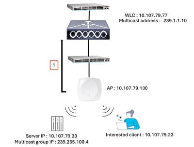
This is a list of the source, destination, and other relevant IP addresses observed in the annotated Wireshark captures. These correspond to the key packet flows shown in the figures, helping to identify which hosts initiated and received each packet.
WLC WMI - 10.107.79.77
AP IP - 10.107.79.130
CAPWAP Multicast group IP address configured on WLC - 239.1.1.10
Multicast source endpoint IP - 10.107.79.33
Multicast traffic IP - 239.255.100.4
Client IP (Destination) - 10.107.79.23
Step 1: AP Sends an IGMP Join to WLC
 AP IGMP Join
The AP joins the CAPWAP multicast group (239.1.1.10) of the controller, using IGMP.
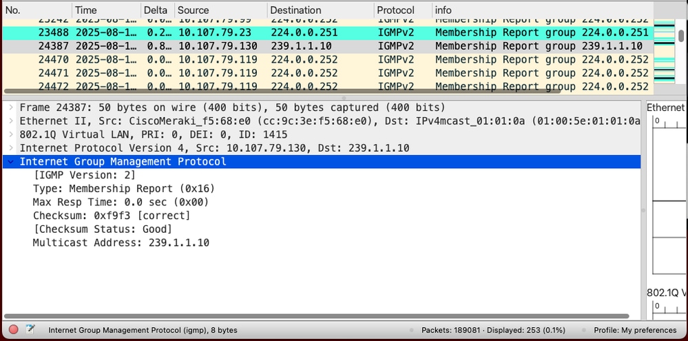 AP IGMP Join to the WLC
Step 2: Client Sends an IGMP Join for Multicast Stream
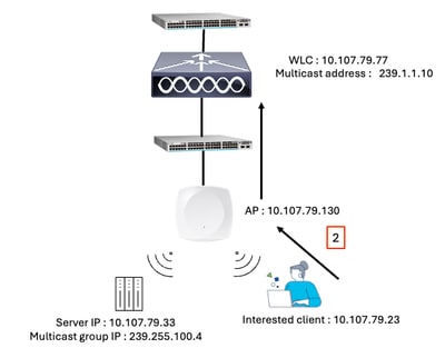 Client IGMP join for multicast stream
The wireless client sends an IGMP join request to indicate interest in a specific multicast group.
The associated Access Point (AP) encapsulates the client IGMP Join request within a CAPWAP tunnel and sends it as unicast traffic to the Wireless LAN Controller (WLC).
Example:
A client sends an IGMP Membership Report for multicast group address 239.255.100.4.
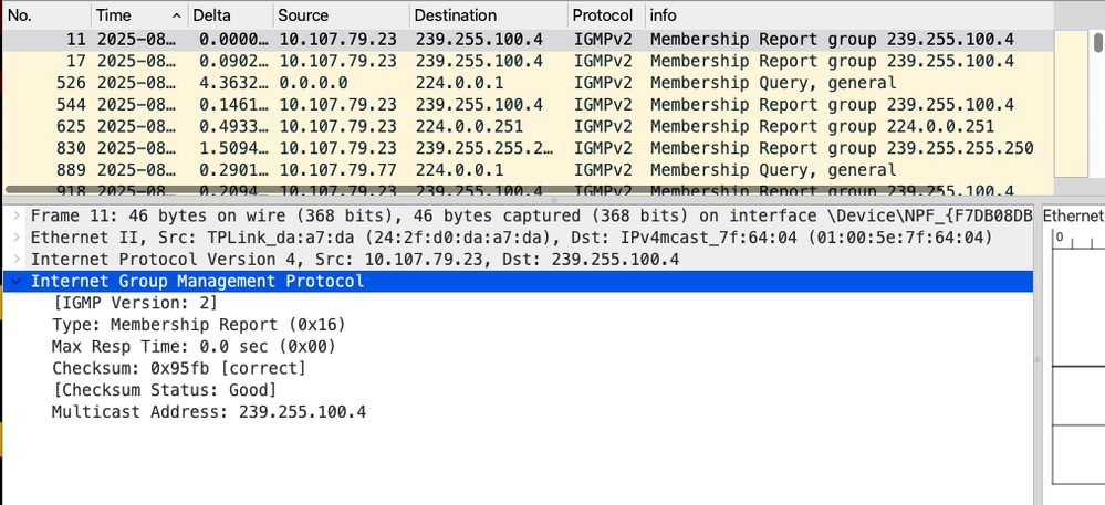 Client sends IGMP membership report for the interested Multicast traffic - Captures collected from endpoint
The AP (IP: 10.107.79.130) encapsulates this request in a CAPWAP tunnel and sends it to the WLC (IP: 10.107.79.77).
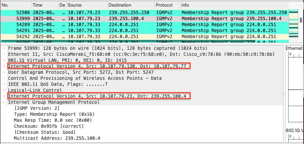 Client IGMP membership report reaches the WLC inside a CAPWAP tunnel - Captures collected from WLC
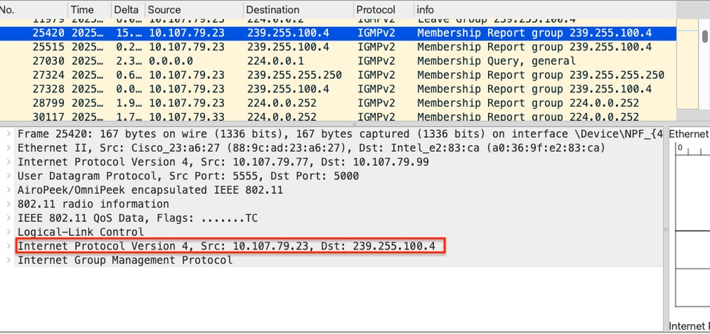 Client IGMP Join - OTA Captures
Step 3: WLC Processes the Join Request
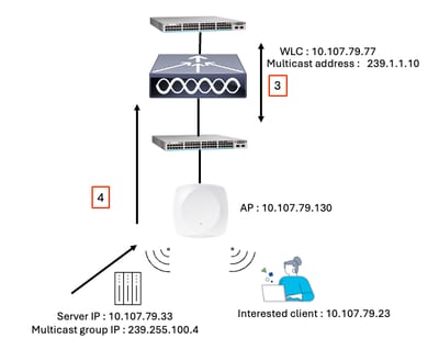 Step 3 and 4
The WLC receives the IGMP Join, records the multicast group address, and sends an IGMP Join or relevant multicast request upstream to its connected switch or router.

Note: In this scenario, the wireless client is also acting as a multicast source.
Step 4: Multicast Traffic Delivery to WLC
The upstream switch or router forwards multicast traffic for the requested group to the WLC.
Example:
The multicast source (10.107.79.33), which is a wireless client, sends multicast traffic to group address 239.255.100.4. Because the source is wireless, the multicast traffic is encapsulated in a CAPWAP tunnel and delivered to the WLC.
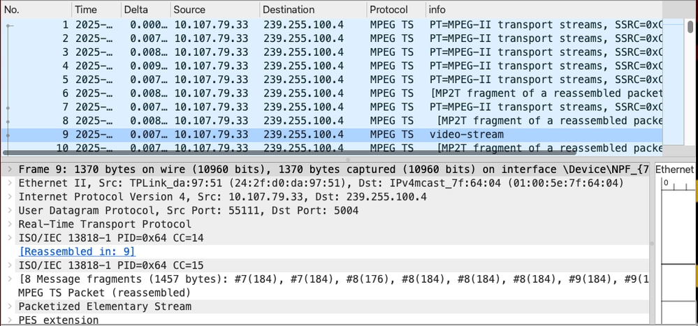 Multicast traffic from the source device
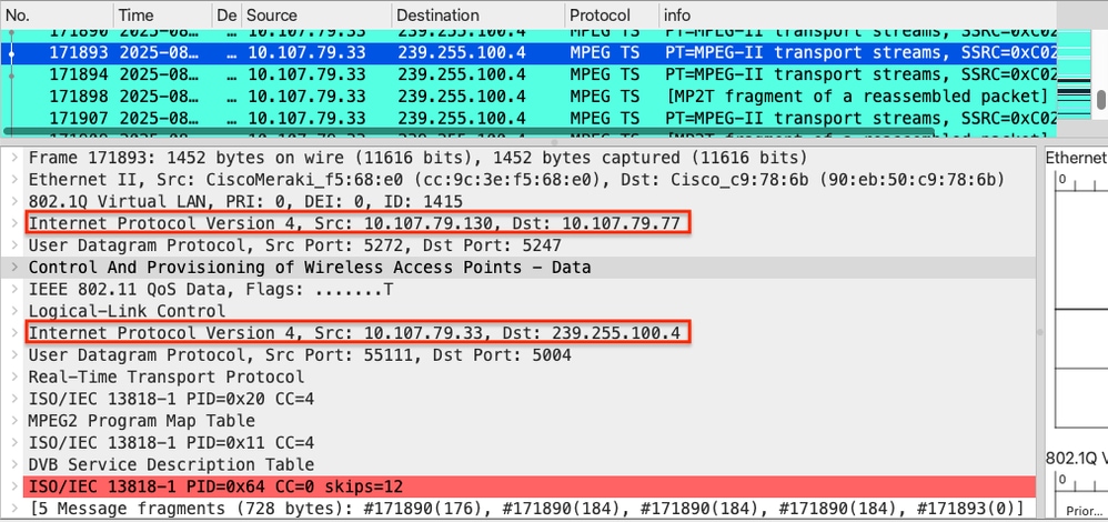 Multicast traffic received from the source inside a CAPWAP Tunnel - Captures collected on WLC
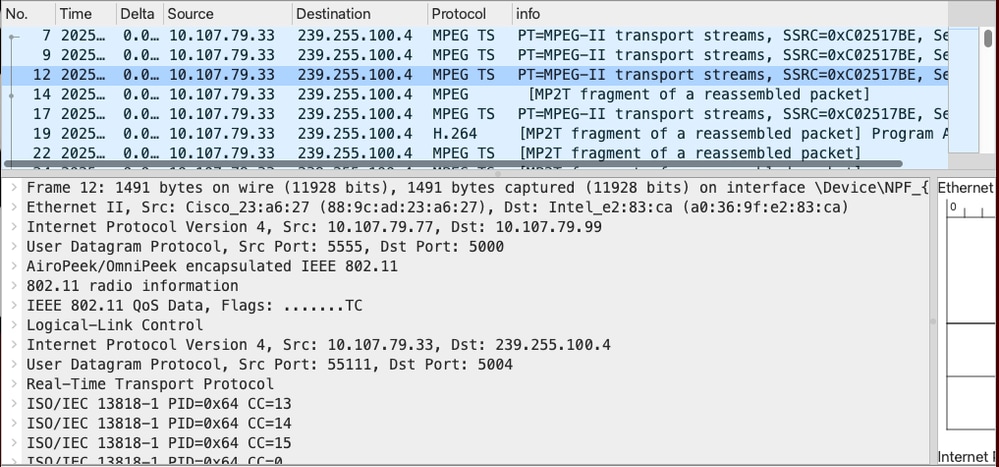 Multicast traffic from the source - OTA
Step 5: CAPWAP Multicast Forwarding to AP(s)
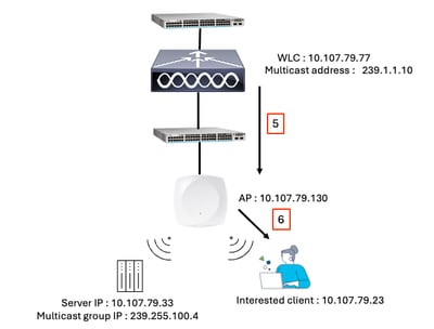 Step 5 and 6
The WLC encapsulates the multicast packets and sends them to all relevant APs using the configured Multicast CAPWAP Group address.
Example:
The WLC forwards multicast traffic to the CAPWAP multicast group address 239.1.1.10. APs that have joined this group via IGMP (Step 1) receive the multicast stream.
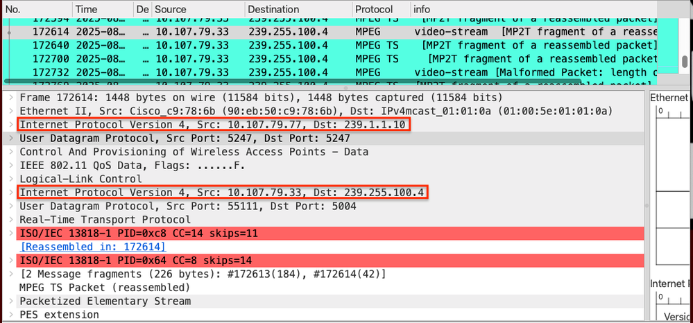 WLC Forwards the traffic to CAPWAP Multicast Group Address
Step 6: AP Forwards the Multicast Traffic to Clients
Each AP decapsulates the multicast packets and forwards them only to the wireless clients that have joined the multicast group.
APs use IGMP snooping to identify interested clients and ensure multicast traffic is delivered only to those clients.
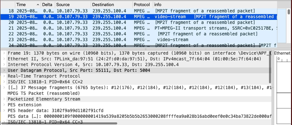 Client receives the multicast traffic - Captures collected from the interested endpoint 10.107.79.23
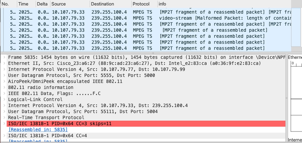 Client receives the multicast traffic - OTA Captures
FlexConnect Local Switching Mode
The client sends an IGMP Join request to the associated AP. The AP processes the IGMP Join and locally switches the multicast traffic without sending it to the WLC. Multicast traffic flows directly from the wired network to the AP, which then forwards it to interested wireless clients.

Note: Enable IP multicast routing globally, configure PIM on the relevant router interfaces and enable IGMP on the switches between the multicast source and the AP. The WLC does not handle multicast data traffic in this mode.
Related Information
Revision History
| Revision | Publish Date | Comments |
|---|---|---|
1.0 |
24-Sep-2025
|
Initial Release |
Contributed by Cisco Engineers
- Kirthika JayapalTechnical Consulting Engineer
Contact Cisco
- Open a Support Case

- (Requires a Cisco Service Contract)
 Feedback