Verify and Troubleshoot Basic NAT Operations
Available Languages
Download Options
Bias-Free Language
The documentation set for this product strives to use bias-free language. For the purposes of this documentation set, bias-free is defined as language that does not imply discrimination based on age, disability, gender, racial identity, ethnic identity, sexual orientation, socioeconomic status, and intersectionality. Exceptions may be present in the documentation due to language that is hardcoded in the user interfaces of the product software, language used based on RFP documentation, or language that is used by a referenced third-party product. Learn more about how Cisco is using Inclusive Language.
Contents
Introduction
This document describes how to troubleshoot IP connectivity problems in a NAT environment.
Prerequisites
Requirements
There are no specific requirements for this document.
Components Used
This document is not restricted to specific software and hardware versions.
The information in this document was created from the devices in a specific lab environment. All of the devices used in this document started with a cleared (default) configuration. If your network is live, ensure that you understand the potential impact of any command.
Conventions
For more information on document conventions, refer to the Cisco Technical Tips Conventions.
Problem
This document describes how to troubleshoot IP connectivity problems in a NAT environment by reviewing the next two examples:
- Ping One Router but not Another Router
- Outside Network Devices Cannot Communicate with Inside Routers
The next basic steps are helpful to determine if there is a problem in the NAT operations:
-
Verify the configuration, and clearly define what NAT is supposed to achieve. Based on the review, you can determine if there is a problem with the configuration. For information on NAT configuration, refer to Configure Network Address Translation.
-
Verify that correct translations exist in the translation table.
-
Use the show and debug commands to verify that the translation occurs.
-
Review in detail what happens to the packet, and verify that routers have the correct routing information to forward the packet along.
Ping One Router but not Another Router
In this first scenario, Router 4 can ping Router 5 (172.16.6.5) but not Router 7 (172.16.11.7):
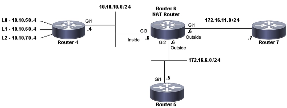 NAT Topology
Router4#ping 172.16.6.5
Type escape sequence to abort.
Sending 5, 100-byte ICMP Echos to 172.16.6.5, timeout is 2 seconds:
.!!!!
Success rate is 80 percent (4/5), round-trip min/avg/max = 1/1/2 ms
Router4#ping 172.16.11.7
Type escape sequence to abort.
Sending 5, 100-byte ICMP Echos to 172.16.11.7, timeout is 2 seconds:
.....
Success rate is 0 percent (0/5)
Router4#
Important considerations about this scenario:
- There are no dynamic Routing Protocols configured at the routers, only static routes are used.
- Router 4 default gateway is Router 6.
- Router 6 is configured with NAT.
interface GigabitEthernet1
 ip address 172.16.11.6 255.255.255.0
 ip nat outside
 negotiation auto
 no mop enabled
 no mop sysid
!
interface GigabitEthernet2
 ip address 172.16.6.6 255.255.255.0
 ip nat outside
 negotiation auto
 no mop enabled
 no mop sysid
!
interface GigabitEthernet3
 ip address 10.10.10.6 255.255.255.0
 ip nat inside
 negotiation auto
 no mop enabled
 no mop sysid
!
!
ip nat pool test 172.16.11.70 172.16.11.71 prefix-length 24
ip nat inside source static 10.10.10.4 172.16.6.14
ip nat inside source list 7 pool test
!
ip access-list standard 7
 10 permit 10.10.50.4
 20 permit 10.10.60.4
 30 permit 10.10.70.4
Troubleshooting
1. First, you need to determine that NAT works correctly. From the previous configuration, it can be determined that Router 4 IP address 10.10.10.4 is statically translated to 172.16.6.14. You can use the show ip nat translation command on Router 6 to verify that the translation does exist in the translation table:
NAT-Router#show ip nat translations
Pro  Inside global         Inside local          Outside local         Outside global
---  172.16.6.14           10.10.10.4            ---                   ---
Total number of translations: 1

NAT-Router#
2. Ensure this translation happens when Router 4 sources IP traffic. You can do this in two ways from Router 6. Run a NAT debug or monitor NAT statistics with the show ip nat statistics command. Because debug commands are the last resort, start with the show command.
3. Monitor the counter to ensure it increases as it receives traffic from Router 4. The counter increments every time the translation table is used to translate an address.
4. Clear the statistics, then display the statistics, then try to ping Router 7 from Router 4, and then display the statistics again.
NAT-Router#clear ip nat statistics
NAT-Router#
NAT-Router#show ip nat statistics
Total active translations: 1 (1 static, 0 dynamic; 0 extended)
Outside interfaces:
  GigabitEthernet1, GigabitEthernet2
Inside interfaces:
  GigabitEthernet3
Hits: 0  Misses: 0
Expired translations: 0
Dynamic mappings:
-- Inside Source
[Id: 1] access-list 7 pool test refcount 0
 pool test: id 1, netmask 255.255.255.0
        start 172.16.11.70 end 172.16.11.71
        type generic, total addresses 2, allocated 0 (0%), misses 0
nat-limit statistics:
 max entry: max allowed 0, used 0, missed 0
In-to-out drops: 0  Out-to-in drops: 0
Pool stats drop: 0  Mapping stats drop: 0
Port block alloc fail: 0
IP alias add fail: 0
Limit entry add fail: 0
NAT-Router#
After you use the ping 172.16.11.7 command on Router 4, the NAT statistics on Router 6 are:
Router4#ping 172.16.11.7
Type escape sequence to abort.
Sending 5, 100-byte ICMP Echos to 172.16.11.7, timeout is 2 seconds:
.....
Success rate is 0 percent (0/5)
Router4#

NAT-Router#show ip nat statistics
Total active translations: 2 (1 static, 1 dynamic; 1 extended)
Outside interfaces:
  GigabitEthernet1, GigabitEthernet2
Inside interfaces:
  GigabitEthernet3
Hits: 4  Misses: 1
Expired translations: 0
Dynamic mappings:
-- Inside Source
[Id: 1] access-list 7 pool test refcount 0
 pool test: id 1, netmask 255.255.255.0
        start 172.16.11.70 end 172.16.11.71
        type generic, total addresses 2, allocated 0 (0%), misses 0
nat-limit statistics:
 max entry: max allowed 0, used 0, missed 0
In-to-out drops: 0  Out-to-in drops: 0
Pool stats drop: 0  Mapping stats drop: 0
Port block alloc fail: 0
IP alias add fail: 0
Limit entry add fail: 0
NAT-Router#
You can see from the show commands the number of hits incremented. In a successful ping from a Cisco router, the number of hits increases by ten. The Internet Control Message Protocol (ICMP) echoes sent by the source router (Router 4) are translated, and the echo reply packets from the destination router (Router 7) need to be translated as well, for a total of ten hits. The loss of five hits is because the echo replies are not translated or are not sent from Router 7.
Next, see if you can find any reason why Router 7 would not send the echo reply packets to Router 4. At this moment, the next steps have happened:
- Router 4 sends ICMP echo packets with a source address of 10.10.10.4 and a destination address of 172.16.11.7.
- After NAT takes place, the packet received by Router 7 has a source address of 172.16.6.14 and a destination address of 172.16.11.7.
- Router 7 needs to reply to 172.16.6.14, and since 172.16.6.14 is not directly connected to Router 7, it needs a route for this network in order to respond.

Note: Another option to confirm if the packets are getting to the destination router is to use an Embedded Packet Capture (EPC) or use a debug ip icmp/debug ip packet with an Access List (ACL).
Now, you need to check Router 7's routing table to verify if a route to 172.16.6.14 exists:
Router7#show ip route
Codes: L - local, C - connected, S - static, R - RIP, M - mobile, B - BGP
       D - EIGRP, EX - EIGRP external, O - OSPF, IA - OSPF inter area
       N1 - OSPF NSSA external type 1, N2 - OSPF NSSA external type 2
       E1 - OSPF external type 1, E2 - OSPF external type 2, m - OMP
       n - NAT, Ni - NAT inside, No - NAT outside, Nd - NAT DIA
       i - IS-IS, su - IS-IS summary, L1 - IS-IS level-1, L2 - IS-IS level-2
       ia - IS-IS inter area, * - candidate default, U - per-user static route
       H - NHRP, G - NHRP registered, g - NHRP registration summary
       o - ODR, P - periodic downloaded static route, l - LISP
       a - application route
       + - replicated route, % - next hop override, p - overrides from PfR
       & - replicated local route overrides by connected

Gateway of last resort is not set

      172.16.0.0/16 is variably subnetted, 2 subnets, 2 masks
C        172.16.11.0/24 is directly connected, GigabitEthernet1
L        172.16.11.7/32 is directly connected, GigabitEthernet1
Router7#
Form the previous output, you can observe that the Router 7 does not have a route for 172.16.6.14 subnet in its routing table. Once this is corrected, and a route is added to the configuration, the ping works. It is useful to monitor NAT statistics with the show ip nat statistics command. However, in a more complex NAT environment with several translations, this show command is no longer useful, and the use of debugs is needed on the router.
Router7#configure terminal Enter configuration commands, one per line. End with CNTL/Z. Router7(config)#ip route 172.16.6.0 255.255.255.0 172.16.11.6 Router7(config)#end Router7#Router4#ping 172.16.11.7 Type escape sequence to abort. Sending 5, 100-byte ICMP Echos to 172.16.11.7, timeout is 2 seconds: !!!!! Success rate is 100 percent (5/5), round-trip min/avg/max = 1/2/8 ms Router4#NAT-Router#show ip nat statistics Total active translations: 2 (1 static, 1 dynamic; 1 extended) Outside interfaces: GigabitEthernet1, GigabitEthernet2 Inside interfaces: GigabitEthernet3 Hits: 9 Misses: 1 Expired translations: 0 Dynamic mappings: -- Inside Source [Id: 1] access-list 7 pool test refcount 0 pool test: id 1, netmask 255.255.255.0 start 172.16.11.70 end 172.16.11.71 type generic, total addresses 2, allocated 0 (0%), misses 0 nat-limit statistics: max entry: max allowed 0, used 0, missed 0 In-to-out drops: 0 Out-to-in drops: 0 Pool stats drop: 0 Mapping stats drop: 0 Port block alloc fail: 0 IP alias add fail: 0 Limit entry add fail: 0 NAT-Router#
Outside Network Devices Cannot Communicate with Inside Routers
In this problem, Router 4 can ping both Router 5 and Router 7, but devices on the 10.10.50.0 network cannot communicate with Router 5 or Router 7.
Router4#ping 172.16.11.7 source 10.10.50.4
Type escape sequence to abort.
Sending 5, 100-byte ICMP Echos to 172.16.11.7, timeout is 2 seconds:
Packet sent with a source address of 10.10.50.4
.....
Success rate is 0 percent (0/5)
Router4#ping 172.16.6.5 source 10.10.50.4
Type escape sequence to abort.
Sending 5, 100-byte ICMP Echos to 172.16.6.5, timeout is 2 seconds:
Packet sent with a source address of 10.10.50.4
.....
Success rate is 0 percent (0/5)
Router4#
The network diagram for this problem remains the same:
 NAT Topology
interface GigabitEthernet1
 ip address 172.16.11.6 255.255.255.0
 ip nat outside
 negotiation auto
 no mop enabled
 no mop sysid
!
interface GigabitEthernet2
 ip address 172.16.6.6 255.255.255.0
 ip nat outside
 negotiation auto
 no mop enabled
 no mop sysid
!
interface GigabitEthernet3
 ip address 10.10.10.6 255.255.255.0
 ip nat inside
 negotiation auto
 no mop enabled
 no mop sysid
!
!
ip nat pool test 172.16.11.70 172.16.11.71 prefix-length 24
ip nat inside source static 10.10.10.4 172.16.6.14
ip nat inside source list 7 pool test
!
ip access-list standard 7
 10 permit 10.10.50.4
 20 permit 10.10.60.4
 30 permit 10.10.70.4
Troubleshooting
From the configuration of Router 6, you can observe that NAT is supposed to dynamically translate 10.10.50.4 to the first available address in the NAT pool called test. The pool consists of addresses 172.16.11.70 and 172.16.11.71. From this problem, you can understand that the packets that Routers 5 and 7 receive either have a source address of 172.16.11.70 or 172.16.11.71. These addresses are on the same subnet as Router 7, so Router 7 must have a directly connected route to this subnet, however, if it does not already have one, Router 5 needs a route to the subnet .
You can use the show ip route command to see that the Router 5 routing table does list 172.16.11.0:
Router5#show ip route
Codes: L - local, C - connected, S - static, R - RIP, M - mobile, B - BGP
       D - EIGRP, EX - EIGRP external, O - OSPF, IA - OSPF inter area
       N1 - OSPF NSSA external type 1, N2 - OSPF NSSA external type 2
       E1 - OSPF external type 1, E2 - OSPF external type 2, m - OMP
       n - NAT, Ni - NAT inside, No - NAT outside, Nd - NAT DIA
       i - IS-IS, su - IS-IS summary, L1 - IS-IS level-1, L2 - IS-IS level-2
       ia - IS-IS inter area, * - candidate default, U - per-user static route
       H - NHRP, G - NHRP registered, g - NHRP registration summary
       o - ODR, P - periodic downloaded static route, l - LISP
       a - application route
       + - replicated route, % - next hop override, p - overrides from PfR
       & - replicated local route overrides by connected

Gateway of last resort is not set

      172.16.0.0/16 is variably subnetted, 3 subnets, 2 masks
C        172.16.6.0/24 is directly connected, GigabitEthernet1
L        172.16.6.5/32 is directly connected, GigabitEthernet1
S        172.16.11.0/24 [1/0] via 172.16.6.6
You can use the show ip route command to see that the Router 7 routing table lists 172.16.11.0 as a directly connected subnet:
Router7#show ip route
Codes: L - local, C - connected, S - static, R - RIP, M - mobile, B - BGP
       D - EIGRP, EX - EIGRP external, O - OSPF, IA - OSPF inter area
       N1 - OSPF NSSA external type 1, N2 - OSPF NSSA external type 2
       E1 - OSPF external type 1, E2 - OSPF external type 2, m - OMP
       n - NAT, Ni - NAT inside, No - NAT outside, Nd - NAT DIA
       i - IS-IS, su - IS-IS summary, L1 - IS-IS level-1, L2 - IS-IS level-2
       ia - IS-IS inter area, * - candidate default, U - per-user static route
       H - NHRP, G - NHRP registered, g - NHRP registration summary
       o - ODR, P - periodic downloaded static route, l - LISP
       a - application route
       + - replicated route, % - next hop override, p - overrides from PfR
       & - replicated local route overrides by connected

Gateway of last resort is not set

      172.16.0.0/16 is variably subnetted, 3 subnets, 2 masks
S        172.16.6.0/24 [1/0] via 172.16.11.6
C        172.16.11.0/24 is directly connected, GigabitEthernet1
L        172.16.11.7/32 is directly connected, GigabitEthernet1
Check the NAT translation table and verify that the expected translation exists. Since the desired translation is created dynamically, you must first send IP traffic sourced from the appropriate address. After a ping is sent, sourced from 10.10.50.4 and destined to 172.16.11.7, the translation table in Router 6 (NAT Router) shows the next output:
NAT-Router#show ip nat translations
Pro  Inside global         Inside local          Outside local         Outside global
---  172.16.6.14           10.10.10.4            ---                   ---
---  172.16.11.70          10.10.50.4            ---                   ---
Total number of translations: 2
Since the expected translation is in the translation table, you know that the ICMP echo packets are appropriately translated. One option is that you can monitor the NAT statistics, but that is not useful in a complex environment. Another option is to run NAT debugging on the NAT Router (Router 6). You can run debug ip nat while you send a ping sourced from 10.10.50.4 destined to 172.16.11.7. The debug results are in the next code example.
Note: When you use any debug command on a router, you could overload the router which causes it to become inoperable. Always use extreme caution, and if possible, never run a debug on a critical production router without the supervision of a Cisco Technical Support engineer.
NAT-Router#show logging
Syslog logging: enabled (0 messages dropped, 0 flushes, 0 overruns)
       Console logging: level debugging, 39 messages logged
       Monitor logging: level debugging, 0 messages logged
       Buffer logging: level debugging, 39 messages logged
       Trap logging: level informational, 33 message lines logged

Log Buffer (4096 bytes):

05:32:23: NAT: s=10.10.50.4->172.16.11.70, d=172.16.11.7 [70]
05:32:23: NAT*: s=172.16.11.7, d=172.16.11.70->10.10.50.4 [70]
05:32:25: NAT*: s=10.10.50.4->172.16.11.70, d=172.16.11.7 [71]
05:32:25: NAT*: s=172.16.11.7, d=172.16.11.70->10.10.50.4 [71]
05:32:27: NAT*: s=10.10.50.4->172.16.11.70, d=172.16.11.7 [72]
05:32:27: NAT*: s=172.16.11.7, d=172.16.11.70->10.10.50.4 [72]
05:32:29: NAT*: s=10.10.50.4->172.16.11.70, d=172.16.11.7 [73]
05:32:29: NAT*: s=172.16.11.7, d=172.16.11.70->10.10.50.4 [73]
05:32:31: NAT*: s=10.10.50.4->172.16.11.70, d=172.16.11.7 [74]
05:32:31: NAT*: s=172.16.11.7, d=172.16.11.70->10.10.50.4 [74]
Router7#show monitor capture cap buffer brief
 ----------------------------------------------------------------------------
 #   size   timestamp     source             destination      dscp    protocol
 ----------------------------------------------------------------------------
   0  114    0.000000   172.16.11.70     ->  172.16.11.7      0  BE   ICMP
   1  114    2.000000   172.16.11.70     ->  172.16.11.7      0  BE   ICMP
   2  114    4.000000   172.16.11.70     ->  172.16.11.7      0  BE   ICMP
   3  114    6.001999   172.16.11.70     ->  172.16.11.7      0  BE   ICMP
   4  114    8.001999   172.16.11.70     ->  172.16.11.7      0  BE   ICMP
As you can see from the previous debug output, the first line shows the source address of 10.10.50.4 translated to 172.16.11.70. The second line shows the destination address of 172.16.11.70 is translated back to 10.10.50.4. This pattern repeats throughout the rest of the debug. This means that NAT Router translates the packets in both directions. Also, from the packet capture it can be seen that Router 7 is indeed receiving the ICMP packets with a source of 172.16.11.70 and a destination of 172.16.11.7.
The subsequent steps are a recap of the current status of this problem:
1. Router 4 sends a packet sourced from 10.10.50.4 destined for 172.16.11.7 (or 172.16.6.5 depending on the test performed).
2. NAT Router performs a NAT translation on the packet and forwards it with a source of 172.16.11.70 and a destination of 172.16.11.7.
3. Router 7 sends a response with a source of 172.16.11.7 and a destination of 172.16.11.70.
4. NAT Router (Router 6) performs NAT on the packet, which results in a packet with source address 172.16.11.7 and destination address 10.10.50.4.
5. NAT Router (Router 6) routes the packet to 10.10.50.4 based on information in its routing table.
At this point, you need to use the show ip route and show ip cef commands to confirm that NAT Router (Router 6) has the necessary routes in its routing table.
NAT-Router#show ip route Codes: L - local, C - connected, S - static, R - RIP, M - mobile, B - BGP D - EIGRP, EX - EIGRP external, O - OSPF, IA - OSPF inter area N1 - OSPF NSSA external type 1, N2 - OSPF NSSA external type 2 E1 - OSPF external type 1, E2 - OSPF external type 2, m - OMP n - NAT, Ni - NAT inside, No - NAT outside, Nd - NAT DIA i - IS-IS, su - IS-IS summary, L1 - IS-IS level-1, L2 - IS-IS level-2 ia - IS-IS inter area, * - candidate default, U - per-user static route H - NHRP, G - NHRP registered, g - NHRP registration summary o - ODR, P - periodic downloaded static route, l - LISP a - application route + - replicated route, % - next hop override, p - overrides from PfR & - replicated local route overrides by connected Gateway of last resort is not set 10.0.0.0/8 is variably subnetted, 2 subnets, 2 masks C 10.10.10.0/24 is directly connected, GigabitEthernet3 L 10.10.10.6/32 is directly connected, GigabitEthernet3 172.16.0.0/16 is variably subnetted, 6 subnets, 2 masks C 172.16.6.0/24 is directly connected, GigabitEthernet2 L 172.16.6.6/32 is directly connected, GigabitEthernet2 L 172.16.6.14/32 is directly connected, GigabitEthernet2 C 172.16.11.0/24 is directly connected, GigabitEthernet1 L 172.16.11.6/32 is directly connected, GigabitEthernet1 L 172.16.11.70/32 is directly connected, GigabitEthernet1NAT-Router#show ip route 10.10.50.4 % Subnet not in table NAT-Router#show ip cef 10.10.50.4 0.0.0.0/0 no route NAT-Router#
After adding the missing route in the NAT Router, the ping is now successful:
NAT-Router#configure terminal
Enter configuration commands, one per line.  End with CNTL/Z.
NAT-Router(config)#ip route 10.10.50.4 255.255.255.255 10.10.10.4
NAT-Router(config)#end
NAT-Router#

Router4#ping 172.16.11.7 source 10.10.50.4
Type escape sequence to abort.
Sending 5, 100-byte ICMP Echos to 172.16.11.7, timeout is 2 seconds:
Packet sent with a source address of 10.10.50.4
!!!!!
Success rate is 100 percent (5/5), round-trip min/avg/max = 1/1/2 ms
Router4#ping 172.16.6.5 source 10.10.50.4
Type escape sequence to abort.
Sending 5, 100-byte ICMP Echos to 172.16.6.5, timeout is 2 seconds:
Packet sent with a source address of 10.10.50.4
!!!!!
Success rate is 100 percent (5/5), round-trip min/avg/max = 1/2/4 ms
Router4#
Checklist for Common Issues
Use this checklist to troubleshoot common issues:
Translation Not Installed in the Translation Table
If you find that the appropriate translation is not installed in the translation table, verify:
- The configuration is correct. It is difficult to get NAT to get what you want sometimes. For some configuration help, refer to Configure Network Address Translation.
- There are not any inbound access lists that deny the entry of packets from the NAT router.
- The NAT router has the appropriate route in the routing table if the packet is goes from inside to outside. Refer to NAT Order of Operation for more information.
- The access list referenced by the NAT command permits all necessary networks.
- There are enough addresses in the NAT pool. This can only be a problem if NAT is not configured for congestion.
- That the router interfaces are appropriately defined as NAT inside or NAT outside.
- For the translation of the payload of Domain Name System (DNS) packets, ensure that translation takes place on the address in the IP header of the packet. If this does not happen, then NAT does not look into the payload of the packet.
Correct Translation Entry is not Being Used
If the correct translation entry is installed in the translation table, but is not used, check:
- Verify there are not any inbound access lists that deny entry of the packets from the NAT router.
- For packets that go from inside to outside, verify there is a route to the destination as this is checked before translation. Refer to NAT Order of Operation for more information.
NAT Operating Correctly but There Are Still Connectivity Problems
Troubleshoot the connectivity problem:
- Verify layer 2 connectivity.
- Verify layer 3 routing information.
- Search for packet filters that cause the problem.
NAT Translation for Port 80 does not Work
This means that NAT translation for port 80 does not work, but the translation for other ports works normally.
To resolve this issue:
- Run the debug ip nat translations and debug ip packet commands in order to see if the translations are correct, and that the correct translation entry is installed in the translation table.
- Verify that the server responds.
- Disable the HTTP server.
- Clear the NAT and ARP tables.
%NAT System Busy - Try Later
The try later error message appears when a show command related to NAT or a show running-config or write memory command is executed. This is caused by the increase in the size of the NAT table. When the size of the NAT table increases, the router runs out of memory.
- Reload the router in order to solve this issue.
- If the error message appears when HSRP SNAT is configured, configure these commands in order to resolve the issue:
- Router(config)#standby delay minimum 20 reload 20
- Router(config)#standby 2 preempt delay minimum 20 reload 20 sync 10
Large Translation Table Increases the CPU
A host can send hundreds of translations, which causes high CPU usage. In other words, it can make the table so large that it causes the CPU to run at 100 percent. The ip nat translation max-entries 300 command creates the 300 per host limit or an aggregate limit of the amount of translations on the router. The workaround is to use the ip nat translation max-entries all-hosts 300 command.
% Public Ip-Address Already Mapped (Internal Ip-Address > Public Ip-Address)
This message appears when you try to configure two internal IP addresses to one public IP address that listens on the same ports.
% X.X.X.X already mapped (172.30.62.101 -> X.X.X.X)In order to correct this, configure the public IP address to have two internal IP addresses and use two public IP addresses in the DNS.
No Entries in the ARP table
This is a result of the no-alias option on the NAT entries. The no-alias option means that the router does not respond for the addresses and does not install an ARP entry. If another router uses a NAT pool as an inside global pool that consists of addresses on an attached subnet, an alias is generated for that address so that the router can answer Address Resolution Protocol (ARP) requests for those addresses. This causes the router to have ARP entries for the fake addresses.
Bad token 0 Wanted TOK_NUMBER|TOK_PUNCT
This error message is just an informational message and does not have any impact on the normal behavior of the device.
Bad token 0, wanted TOK_NUMBER|TOK_PUNCTThe error means that NAT attempts to do a layer 4 fix on the address in an FTP open and cannot find the IP addresses it needs to translate in the packet. The reason why the message includes tokens is that IP addresses in the packet are found by the search for a token, or a set of symbols, in the IP packet, in order to find the details needed to translate.
When an FTP session is initiated, it negotiates two channels, a command channel and a data channel. These are both IP addresses with different port numbers. The FTP client and server negotiate a second data channel to transfer files to. The packet exchanged through control channel has the format "PORT,i,i,i,i,p,p", where i,i,i,i are the four bytes of an IP address and p,p specifies the port. NAT tries to match this pattern and to translate address/port, if necessary. NAT must translate both channel schemes. NAT scans for numbers in the command stream, until it thinks it has found a port command that requires translation. It then parses out the translation, which it calculates with the same format.
If the packet is corrupt, or the FTP server or client has malformed commands, NAT cannot properly calculate the translation and it generates that error. You can set the FTP client to passive so that it initiates both channels.
Related Information
Revision History
| Revision | Publish Date | Comments |
|---|---|---|
3.0 |
14-Aug-2023
|
Updated Alt Text, Article Description, Headings, Spelling and Formatting. |
2.0 |
05-Jul-2022
|
Recertification |
1.0 |
14-Nov-2001
|
Initial Release |
Contributed by Cisco Engineers
- Julio JimenezCisco TAC Engineer
 Feedback
Contact Cisco
- Open a Support Case

- (Requires a Cisco Service Contract)