Deploy C8000v High Availability Configuration on AWS
Available Languages
Download Options
Bias-Free Language
The documentation set for this product strives to use bias-free language. For the purposes of this documentation set, bias-free is defined as language that does not imply discrimination based on age, disability, gender, racial identity, ethnic identity, sexual orientation, socioeconomic status, and intersectionality. Exceptions may be present in the documentation due to language that is hardcoded in the user interfaces of the product software, language used based on RFP documentation, or language that is used by a referenced third-party product. Learn more about how Cisco is using Inclusive Language.
Contents
Introduction
This document describes how to setup a High Availability environment with Catalyst 8000v routers on Amazon Web Services cloud.
Prerequisites
Requirements
Cisco recommends that you have previous knowledge of the these topics:
- General knowledge of AWS Console and its components
- Understanding of Cisco IOS® XE software
- Basic knowledge of HA feature.
Components Used
These components are required for this configuration example:
- An Amazon AWS account with administrator role
- Two C8000v devices running Cisco IOS® XE 17.15.3a and 1 Ubuntu 22.04 LTS VM AMIs in the same region
The information in this document was created from the devices in a specific lab environment. All of the devices used in this document started with a cleared (default) configuration. If your network is live, ensure that you understand the potential impact of any command.
Topology
There are various scenarios of HA deployment based on the network requirements. For this example, HA redundancy is configured with these settings:
- 1x - Region
- 1x - VPC
- 3x - Availability Zones
- 6x - Network Interfaces/Subnets (3x Public Facing/3x Private Facing)
- 2x - Route Tables ( Public & Private )
- 2x - C8000v routers (Cisco IOS® XEDenali 17.15.3a)
- 1x - VM (Linux/Windows)
There are 2 C8000v routers in an HA pair, in two different availability zones. Think of each availability zone as a separate datacenter for additional hardware resiliency.
The third zone is a VM, which simulates a device in a private datacenter. For now, internet access is enabled through the public interface so that you can access and configure the VM. Generally, all normal traffic must flow through the private route table.
To simulate traffic, initiate a ping from the Virtual Machine’s private interface, traversing the private route table through R1 to reach 8.8.8.8. In the event of a failover, verify that the private route table has automatically updated to route traffic through the private interface of the R2 Router.
Network Diagram
Table Summary
To summarize the topology, here is the table with the most important values from each component in the lab. The information provided in this table is exclusive for this lab.

Tip: Using this table helps maintain a clear overview of key variables throughout the guide. Collecting the information in this format is recommended to streamline the process.
| Device | Availability Zone | Interfaces | IP Addresses | RTB | ENI |
| R1 | us-east-1a | GigabitEthernet1 | 10.100.10.254 | rtb-0d0e48f25c9b00635 (public) | eni-0645a881c13823696 |
| GigabitEthernet2 | 10.100.110.254 | rtb-093df10a4de426eb8 (private) | eni-070e14fbfde0d8e3b | ||
| R2 | us-east-1b | GigabitEthernet1 | 10.100.20.254 | rtb-0d0e48f25c9b00635 (public) | eni-0a7817922ffbb317b |
| GigabitEthernet2 | 10.100.120.254 | rtb-093df10a4de426eb8 (private) | eni-0239fda341b4d7e41 | ||
| Linux VM | us-east-1c | ens5 | 10.100.30.254 | rtb-0d0e48f25c9b00635 (public) | eni-0b28560781b3435b1 |
| ens6 | 10.100.130.254 | rtb-093df10a4de426eb8 (private) | eni-05d025e88b6355808 |
Restrictions
- On any subnet created, do not use the first available address of that subnet. These IP addresses are used by the AWS services internally.
- Do not configure the public interfaces of the C8000v devices inside a VRF. HA does not work properly if this is set.
Configuration
The general flow of configuration is focused to create the requested VMs in the proper region and move your way down to the most specific configuration such as routes and interfaces of each one of them. However, it is recommended to understand the topology first and configure it in any order desired.
Step 1. Select a Region
For this deployment guide, the US West (North Virginia) - us-east-1 region is selected as the VPC region.
Step 2. Create the VPC
On the AWS Console, navigate to VPC > VPC Dashboard > Create VPC.
When you create the VPC, select the VPC only option. You can assign a /16 network to use as you please.
On this deployment guide, the 10.100.0.0/16 network is selected:
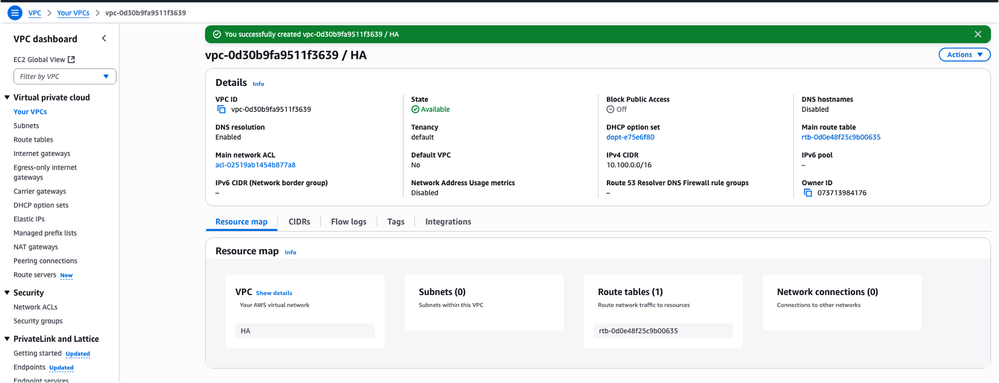
After clicking Create VPC, the VPC-0d30b9fa9511f3639 with HA tag is now created:
Step 3. Create a Security Group for the VPC
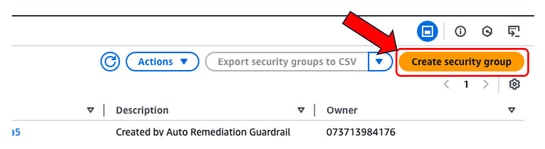
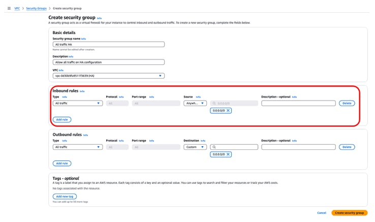
In AWS, Security Groups function like ACLs, allowing or denying traffic to configured VMs within a VPC. On the AWS Console, navigate to VPC > VPC Dashboard > Security > Security Groups section and click Create security group.
Under Inbound Rules, define what traffic you wish to allow for. For this example, All Traffic is selected by using the 0.0.0.0/0 network.
Step 4. Create an IAM Role with a Policy and Associate to the VPC
IAM grants to your AMIs the required access to Amazon APIs. The C8000v is used as a proxy to call AWS API commands to modify the route table in AWS. By default, EC2 instances are not allowed access to APIs. For this reason, a new IAM role must be created which is going to applied during AMI creations.
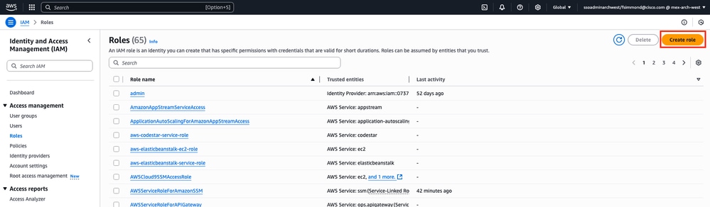
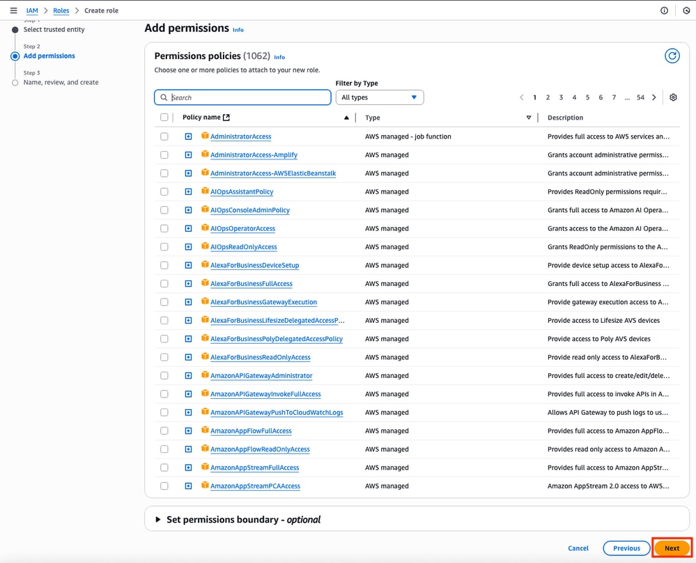
Browse to the IAM dashboard, and navigate to Access Management > Roles > Create Role. This process consists of 3 steps:
First, select the AWS Service option on the Trusted entity type section and EC2 as the service assigned for this policy.
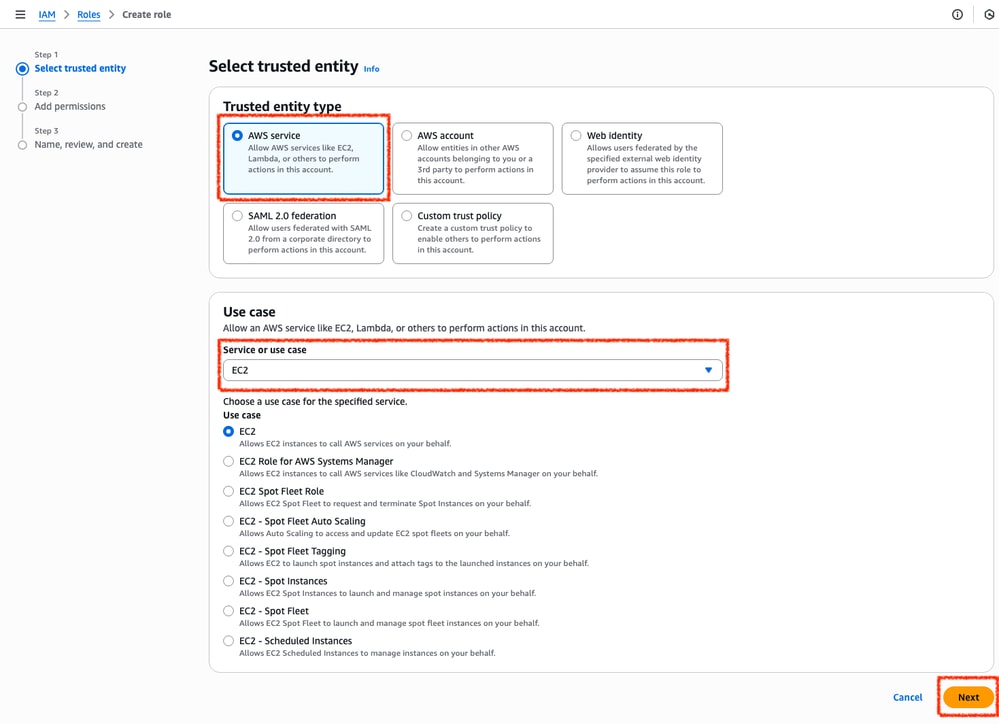
When finished, click Next:
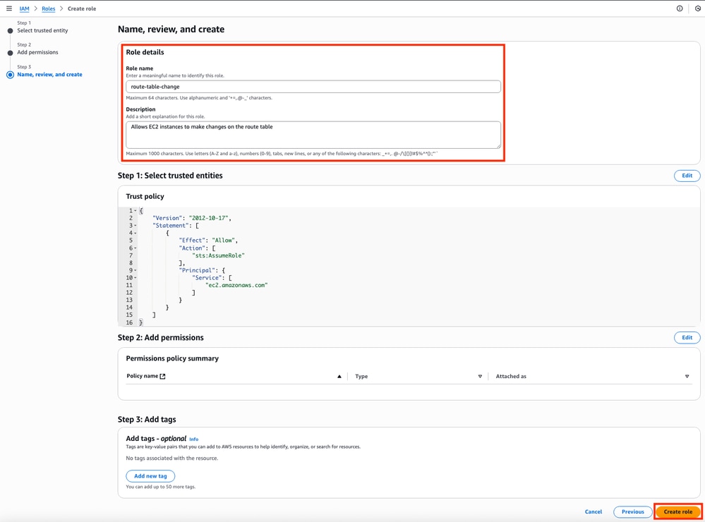
Finally, set the Role Name and click the Create Role button.
Step 5. Create and Attach a Trust Policy to an IAM Role
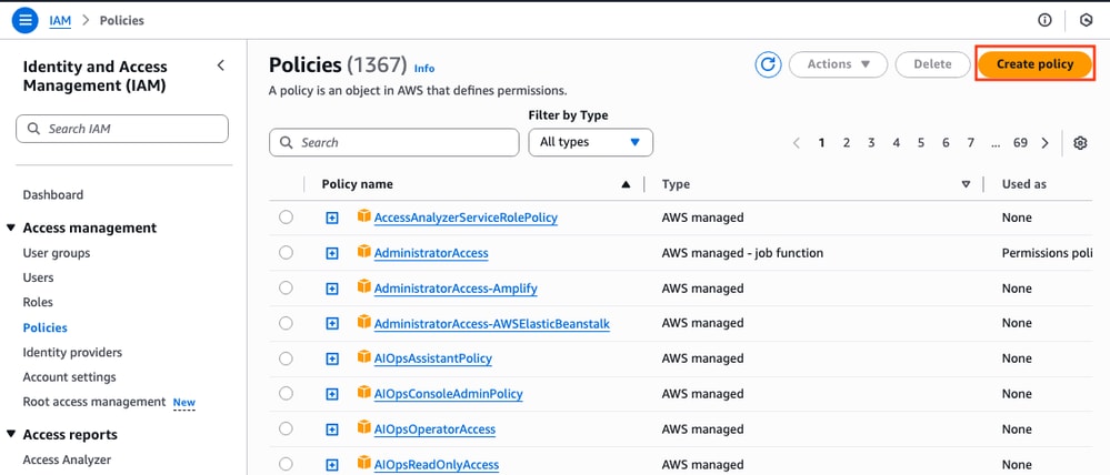
Once the Role is created, a Trust Policy must be made to acquire the skill of modifying the AWS routing tables when needed. Move to the Policies section on the IAM dashboard. Click Create Policy button. This process consists of 2 steps:
First, make sure that the Policy Editor is using JSON and apply the commands that are shown below. Once configured, click Next: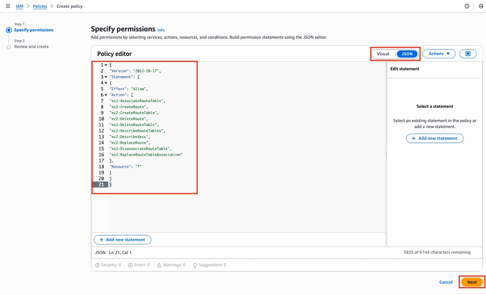
This is the text code used in the image:
{
"Version": "2012-10-17",
"Statement": [
{
"Effect": "Allow",
"Action": [
"ec2:AssociateRouteTable",
"ec2:CreateRoute",
"ec2:CreateRouteTable",
"ec2:DeleteRoute",
"ec2:DeleteRouteTable",
"ec2:DescribeRouteTables",
"ec2:DescribeVpcs",
"ec2:ReplaceRoute",
"ec2:DisassociateRouteTable",
"ec2:ReplaceRouteTableAssociation"
],
"Resource": "*"
}
]
}
Later, set the Policy Name and click Create Policy.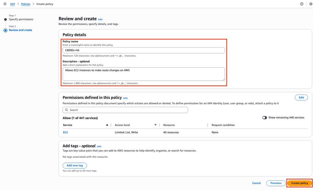
Once the policy is created, filter and select the policy then click Attach option on the Actions drop down menu.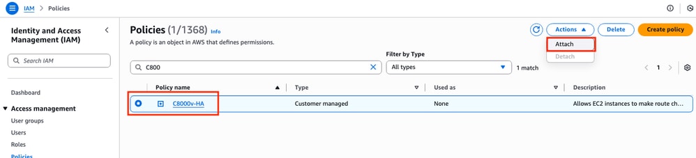
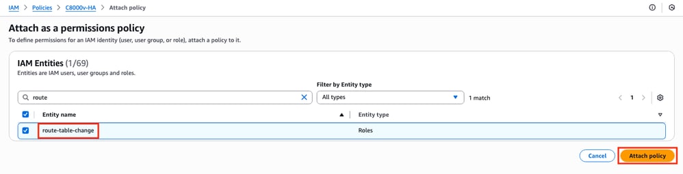
A new window is open. In the IAM Entities section, filter and select the IAM Role created and click Attach policy.
Step 6.Configure and Launch the C8000v Instances
Each C8000v router is going to have 2 interfaces (1 public, 1 private) and is going to be created on its own Availability Zone.
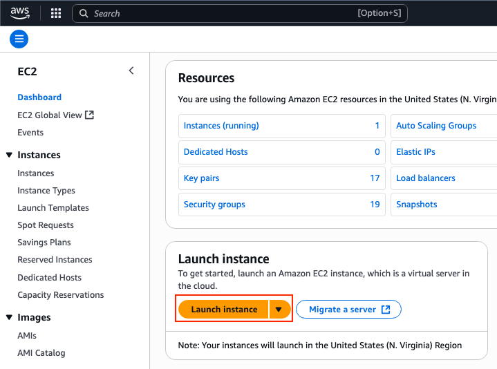
On the EC2 Dashboard, click Launch Instances:
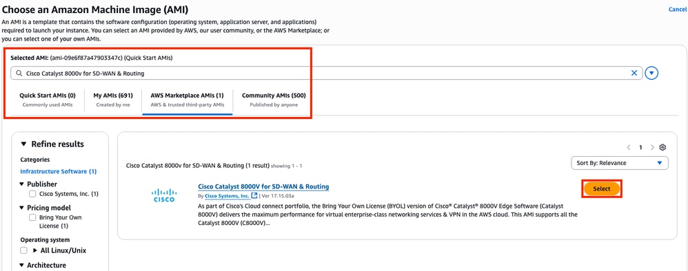
Filter the AMI database with the name Cisco Catalyst 8000v for SD-WAN & Routing. On the AWS Marketplace AMIs list, click Select.
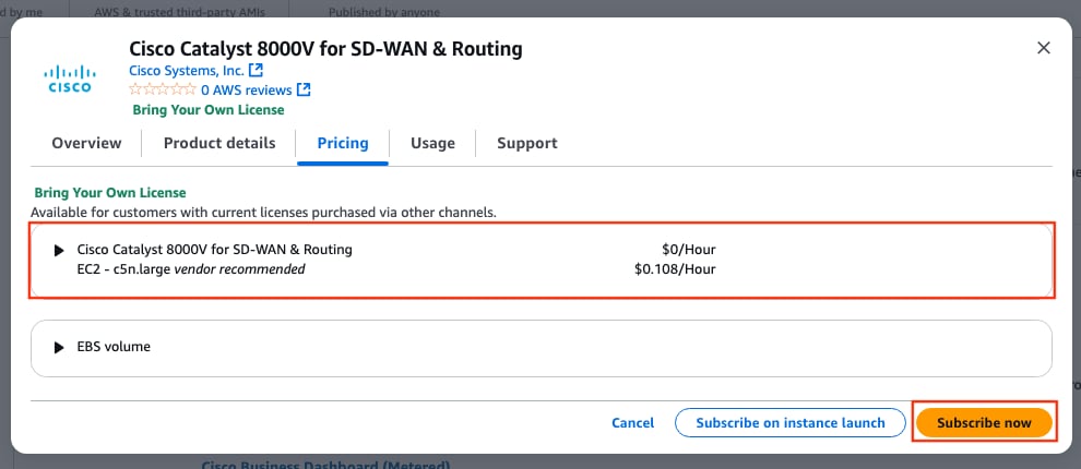
Select the corresponding size for the AMI. For this example, the c5n.large size is selected. This can depend on the capacity required for your network. Once selected, click Subscribe now.
Step 6.1. Configure the Key Pair for Remote Access
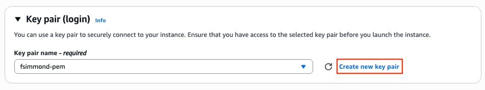
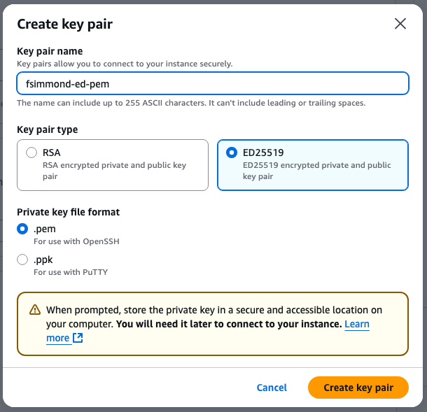
Once subscribed to the AMI, a new window with multiple options is displayed. On the Key pair (login) section, if a keypair is not present, click Create new key pair. You can reuse a single key for every device created.
A new pop-up window is displayed. For this example, a .pem key file with ED25519 encryption is created. Once everything is set, click Create key pair.
Step 6.2. Create and Configure the Subnets for the AMI
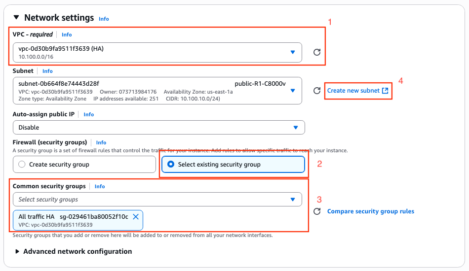
On the Network Settings section, click Edit. Some new options inside the section are now available:
1. Select the desired VPC for this work. For this example, the VPC called HA is selected.
2. On the Firewall (security groups) section, select Select existing security group.
3. Once option 2 is selected, the Common security groups option is available. Filter and select the desired security group. For this example, the All traffic HA security group is selected.
4. (Optional) If no subnets for these device are created, click the Create new subnet.
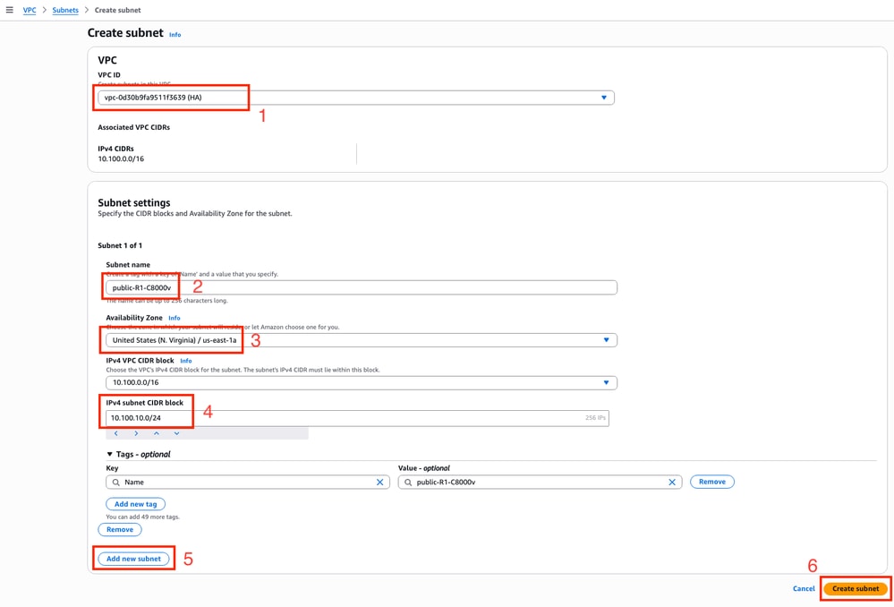
A new tab on the web browser is open, leading you to the Create subnet section:
1. Select the corresponding VPC for this configuration from the drop-down list.
2. Set a name for the new subnet.
3. Define the Availability Zone for this subnet. (Please refer to the Topology section of this document for more information of the setting)
4. Set the subnet block that belongs on the VPC CIDR block.
5. Additionally, all the subnets that are going to be used can be created by clicking the Add new subnet section and repeat the steps from 2 to 4 for each subnet.
6. Once finished, click Create subnet. Navigate to the previous page to continue with the settings.
On the Subnet subsection from the Network Settings section, click Refresh icon to get the created subnets on the drop-down list.
Step 6.3. Configure the AMI Interfaces
On the Network Settings section, expand the Advanced Network configuration subsection. These options are displayed:
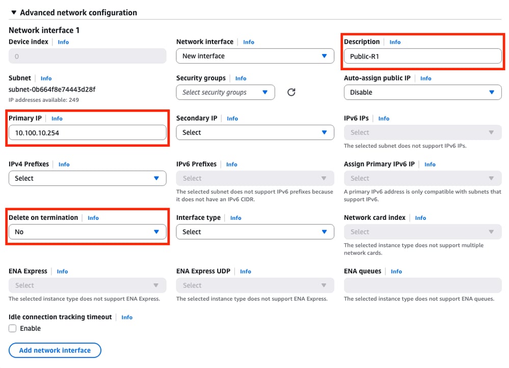
On this menu, set the Description, Primary IP, Delete on termination parameters.
For the Primary IP parameter, use any IP address except for the first available address of the subnet. This is used internally by AWS.
The Delete on termination parameter on this example is set as No. However, this can be set to yes depending of your environment.
Due to this topology, a second interface is needed for the private subnet. Click Add network interface and this prompt is displayed. However, the interface provides the option to select the subnet this time:
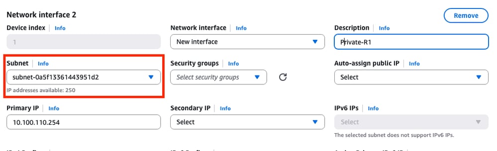
Once all the parameters are set as was made on the Network Interface 1, continue with the next steps.
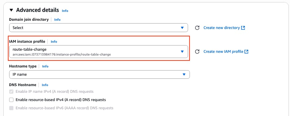
Step 6.4. Set the IAM Instance Profile to the AMI
Under the Advanced details section, select the created IAM role on the IAM instance profile parameter:
Step 6.5. (Optional) Set the Credentials on the AMI
Under the Advanced details section, navigate to the User data - optional section and apply this setting to set a username and password while the instance is created:
ios-config-1="username <username> priv 15 pass <password>"

Note: The username provided by AWS to SSH into the C8000v can be incorrectly listed as root. Change this to ec2-user if necessary.
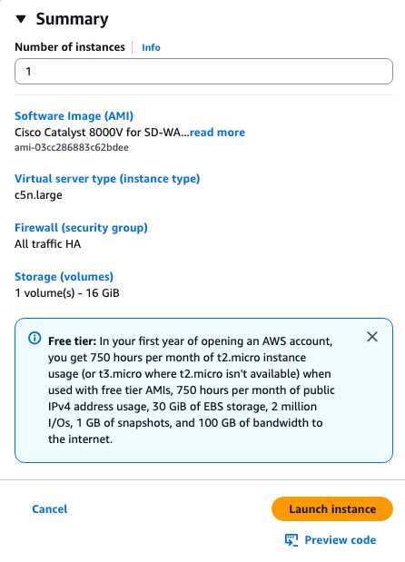
Step 6.6. Finish the Instance Configuration
Once everything is configured, click Launch Instance:
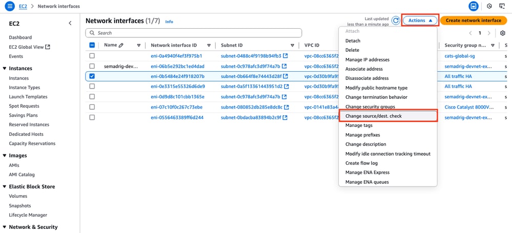
Step 6.7. Disable Source/Destination Check on the ENIs
Once the Instance is created, disable the src/dst check functionality on AWS to get the connectivity between interfaces in the same subnet. On the EC2 Dashboard > Network & Security > Network interfaces section, select the ENIs and click Actions > Change source/dest. check.
Note: You must select the ENIs one by one to get this option available.
A new window is displayed. On the new menu, disable the Enable checkbox and click Save.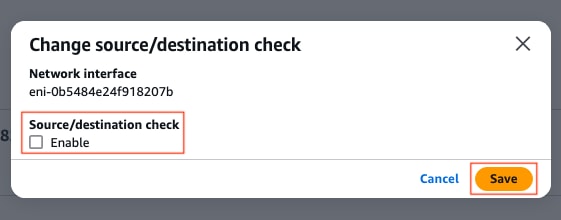
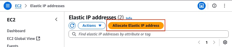
Step 6.8. Create and Associate an Elastic IP to the Public ENI of the Instance
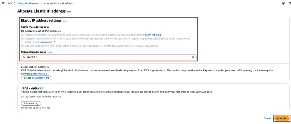
On the EC2 Dashboard > Network & Security > Elastic IPs section, click Allocate Elastic IP address.
The page leads you to the another section. For this example, the Amazon pool of IPv4 addresses option is selected along with the availability zone us-east-1. Once finished, click Allocate.
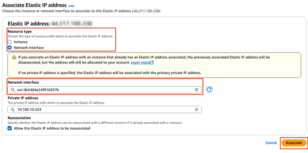
When the IP address is created, assign the IP address to the public interface of the instance. On the EC2 Dashboard > Network & Security > Elastic IPs section, click Actions > Associate Elastic IP address.
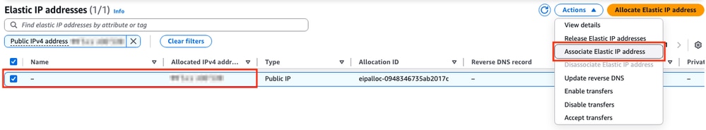
In this new section, select the Network interface option and look for the public ENI of the corresponding interface. Associate the corresponding public IP address and click Associate.
Note: To get the proper ENI ID, navigate to the EC2 Dashboard > Instances section. Then select the instance and check the Networking section. Look for the IP address of your public interface to get the ENI value on the same row.
Step 7. Repeat Step 6 to Create the Second C8000v Instance for HA
Please refer to the Topology section of this document to have the corresponding information for each interface and repeat the same steps from 6.1 to 6.6.
Step 8. Repeat Step 6 to Create a VM (Linux/Windows) from the AMI Marketplace
For this example, Ubuntu server 22.04.5 LTS is selected from the AMI Marketplace as the internal host.
ens5 is created by default for the public interface. For this example, create a second interface (ens6 on the device) for the private subnet.
ubuntu@ip-10-100-30-254:~$ sudo apt install net-tools
...
ubuntu@ip-10-100-30-254:~$ ifconfig
ens5: flags=4163<UP,BROADCAST,RUNNING,MULTICAST> mtu 9001
inet 10.100.30.254 netmask 255.255.255.0 broadcast 10.100.30.255
inet6 fe80::51:19ff:fea2:1151 prefixlen 64 scopeid 0x20<link>
ether 02:51:19:a2:11:51 txqueuelen 1000 (Ethernet)
RX packets 1366 bytes 376912 (376.9 KB)
RX errors 0 dropped 0 overruns 0 frame 0
TX packets 1417 bytes 189934 (189.9 KB)
TX errors 0 dropped 0 overruns 0 carrier 0 collisions 0

ens6: flags=4163<UP,BROADCAST,RUNNING,MULTICAST> mtu 9001
inet 10.100.130.254 netmask 255.255.255.0 broadcast 10.100.130.255
inet6 fe80::3b:7eff:fead:dbe5 prefixlen 64 scopeid 0x20<link>
ether 02:3b:7e:ad:db:e5 txqueuelen 1000 (Ethernet)
RX packets 119 bytes 16831 (16.8 KB)
RX errors 0 dropped 0 overruns 0 frame 0
TX packets 133 bytes 13816 (13.8 KB)
TX errors 0 dropped 0 overruns 0 carrier 0 collisions 0
Note: If any change is made on the interfaces, flap the interface or reload the VM to get these changes applied.
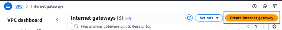
Step 9. Create and Configure an Internet Gateway (IGW) for the VPC
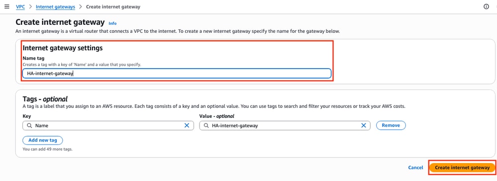
On the VPC Dashboard > VIrtual private cloud > Internet gateways section, click Create internet gateway.
In this new section, create a name tag for this gateway and and click Create internet gateway.
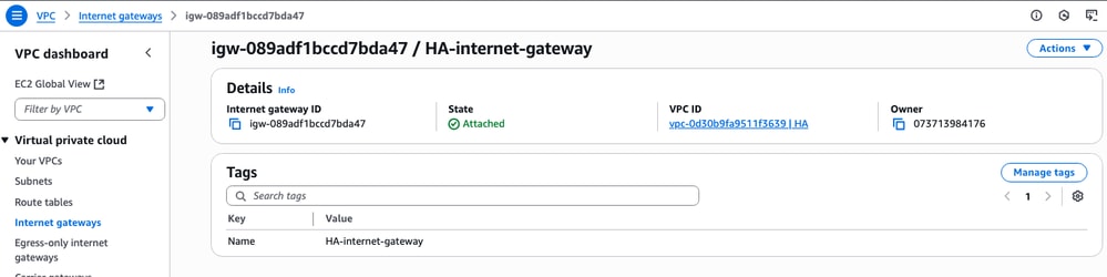
Once the IGW is created, attach it to your corresponding VPC. Navigate to the VPC Dashboard > Virtual Private Cloud > Internet Gateway section and select the corresponding IGW. Click Actions > Attach to VPC.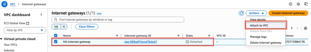
In this new section, select the VPC called HA. For this example, click Attach internet gateway.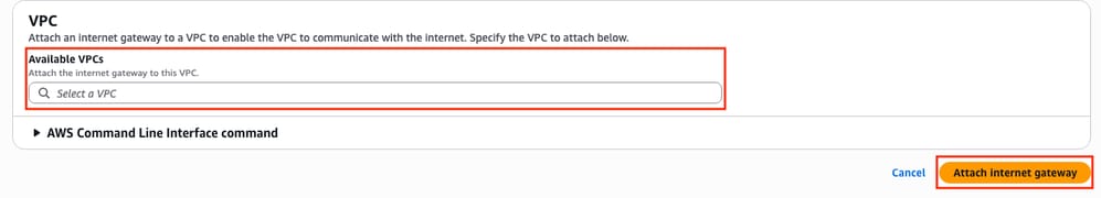
The IGW must indicate the Attached state as it is shown:
Step 10. Create and Configure Route Tables on AWS for Public and Private subnets
Step 10.1. Create and Configure the Public Route Table
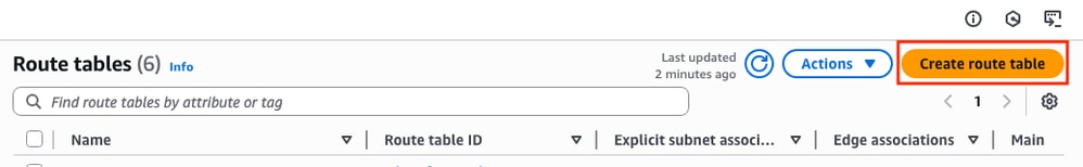
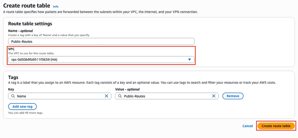
In order to establish the HA on this topology, associate all the public and private subnets on their corresponding route tables. In the VPC Dashboard > Virtual Private Cloud > Route tables section, click Create route table.
In the new section, select the corresponding VPC for this topology. Once selected, click Create route table.
In the Route tables section, select the created table and click Actions > Edit Subnet associations.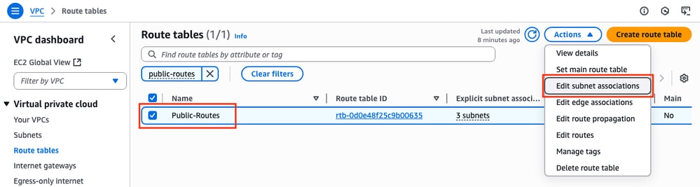
Then, select the corresponding subnets and click Save associations.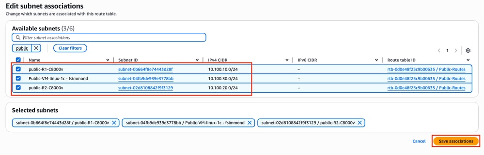
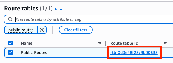
Once the subnets are associated, click the Route table ID hyperlink to add the proper routes for the table. Then, click Edit Routes:
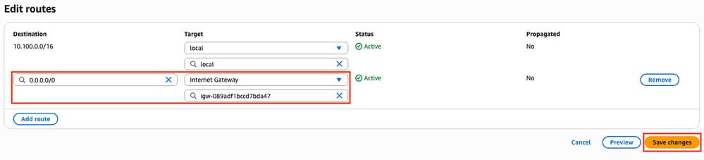
In order to get Internet access, click Add route and link this public route table with the IGW created on Step 9 with these parameters. Once selected, click Save changes:
Step 10.2. Create and Configure the Private Route Table
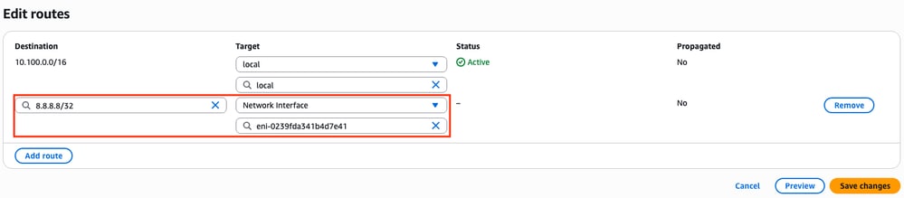
Now that the public route table is created, replicate Steps 10 for the private route and private subnets except for the addition of the Internet Gateway on its routes. For this example, the routing table looks like this since the traffic for 8.8.8.8 must go through the private subnet in this example:
Step 11. Check and Configure Basic Network Configuration, Network Address Translation (NAT), GRE Tunnel with BFD and Routing Protocol
Once the Instances and its routing configuration on AWS is prepared, configure the devices:
C8000v R1 configuration:
interface Tunnel1
ip address 192.168.200.1 255.255.255.0
bfd interval 500 min_rx 500 multiplier 3
tunnel source GigabitEthernet1
tunnel destination <Public IPv4 address of C8000v R2>
!
interface GigabitEthernet1
ip address 10.100.10.254 255.255.255.0
ip nat outside
negotiation auto
!
interface GigabitEthernet2
ip address 10.100.110.254 255.255.255.0
ip nat inside
negotiation auto
!
router eigrp 1
bfd interface Tunnel1
network 192.168.200.0
passive-interface GigabitEthernet1
!
ip access-list standard 10
10 permit 10.100.130.0 0.0.0.255
!
ip nat inside source list 10 interface GigabitEthernet1 overload
!
ip route 0.0.0.0 0.0.0.0 GigabitEthernet1 10.100.10.1
ip route 10.100.130.0 255.255.255.0 GigabitEthernet2 10.100.110.1
C8000v R2 configuration:
interface Tunnel1
ip address 192.168.200.2 255.255.255.0
bfd interval 500 min_rx 500 multiplier 3
tunnel source GigabitEthernet1
tunnel destination<Public IPv4 address of C8000v R1>
!
interface GigabitEthernet1
ip address 10.100.20.254 255.255.255.0
ip nat outside
negotiation auto
!
interface GigabitEthernet2
ip address 10.100.120.254 255.255.255.0
negotiation auto
!
router eigrp 1
bfd interface Tunnel1
network 192.168.200.0
passive-interface GigabitEthernet1
!
ip route 0.0.0.0 0.0.0.0 GigabitEthernet1 10.100.20.1
ip route 10.100.130.0 255.255.255.0 GigabitEthernet2 10.100.120.1
!
ip access-list standard 10
10 permit 10.100.130.0 0.0.0.255
!
ip nat inside source list 10 interface GigabitEthernet1 overload
!

ip route 0.0.0.0 0.0.0.0 GigabitEthernet1 10.100.20.1
ip route 10.100.130.0 255.255.255.0 GigabitEthernet2 10.100.120.1
Step 12. Configure High Availability (Cisco IOS® XE Denali 16.3.1a or later)
Now that the redundancy and connection among VMs are set, configure the HA settings to define the routing changes. Set the Route-table-id, Network-interface-id and CIDR values that must be set after an AWS HA error such as BFD peer down.
Router(config)# redundancy
Router(config-red)# cloud provider aws (node-id)
bfd peer <IP address of the remote device>
route-table <Route table ID>
cidr ip <traffic to be monitored/prefix>
eni <Elastic network interface (ENI) ID>
region <region-name>
The bfd peer parameter is related to the Tunnel peer IP address. This can be checked using the show bfd neighbor output:
R1(config)#do sh bfd neighbors

IPv4 Sessions
NeighAddr LD/RD RH/RS State Int
192.168.200.2 4097/4097 Up Up Tu1
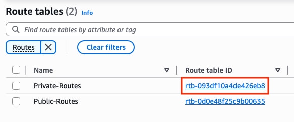
The route-table parameter is related to the Private Route Table ID located in the VPC Dashboard > Virtual Private Cloud > Route Tables section. Copy the corresponding Route Table ID.
The cidr ip parameter is related with the route prefix added on the Private Route Table (routes created on Step 10.2):
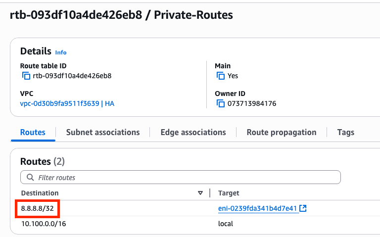
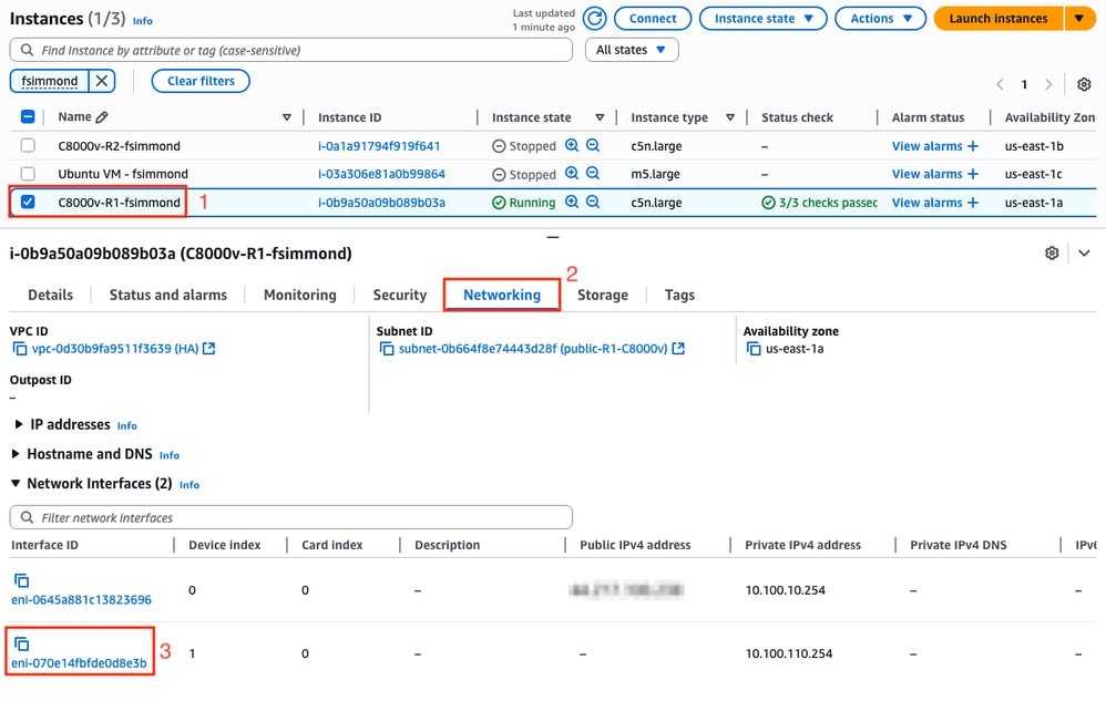
The eni parameter is related with the ENI ID of the corresponding private interface of the Instance that is being configured. For this example, the ENI ID of the interface GigabitEthernet2 of the instance is used:
The region parameter is related with the code name found in the AWS documentation for the region where the VPC is located. For this example, the us-east-1 region is used.
However, this list can change or grow. To find the latest updates, visit AmazonRegion and Availability Zonesdocument.
Taking all this information into account, here is the configuration example for each router in the VPC:
Configuration Example for C8000v R1:
redundancy
 cloud provider aws 1
  bfd peer 192.168.200.2
  route-table rtb-093df10a4de426eb8
  cidr ip 8.8.8.8/32
  eni eni-070e14fbfde0d8e3b
  region us-east-1
Configuration Example for C8000v R2:
redundancy
 cloud provider aws 1
  bfd peer 192.168.200.1
  route-table rtb-093df10a4de426eb8
  cidr ip 8.8.8.8/32
  eni eni-0239fda341b4d7e41
  region us-east-1
Verification
1. Check that status of the C8000v R1 instance. Confirm that the Tunnel and the Cloud redundancy is up and running.
R1#show bfd neighbors

IPv4 Sessions
NeighAddr LD/RD RH/RS State Int
192.168.200.2 4097/4097 Up Up Tu1


R1#show ip eigrp neighbors
EIGRP-IPv4 Neighbors for AS(1)
H Address Interface Hold Uptime SRTT RTO Q Seq
(sec) (ms) Cnt Num
0 192.168.200.2 Tu1 10 00:16:52 2 1470 0 2


R1#show redundancy cloud provider aws 1
Provider : AWS node 1
BFD peer = 192.168.200.2
BFD intf = Tunnel1
route-table = rtb-093df10a4de426eb8
cidr = 8.8.8.8/32
eni = eni-070e14fbfde0d8e3b
region = us-east-1
2. Run a continuous ping to 8.8.8.8 from the Host VM that is behind the routers. Please make sure that the ping is going through the private interface:
ubuntu@ip-10-100-30-254:~$ ping -I ens6 8.8.8.8
PING 8.8.8.8 (8.8.8.8) from 10.100.130.254 ens6: 56(84) bytes of data.
64 bytes from 8.8.8.8: icmp_seq=1 ttl=114 time=1.36 ms
64 bytes from 8.8.8.8: icmp_seq=2 ttl=114 time=1.30 ms
64 bytes from 8.8.8.8: icmp_seq=3 ttl=114 time=1.34 ms
64 bytes from 8.8.8.8: icmp_seq=4 ttl=114 time=1.28 ms
64 bytes from 8.8.8.8: icmp_seq=5 ttl=114 time=1.31 ms
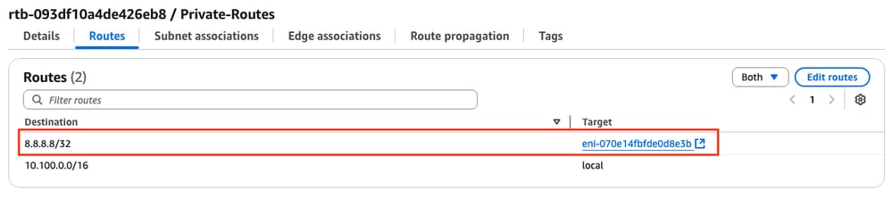
3. Open the AWS WebGUI and check the status of the routing table. The current ENI belongs to the private interface of the R1 instance:
4. Trigger the route change by shutting down the Tunnel1 interface on the R1 Instance to simulate a HA failover event:
R1#config t
R1(config)#interface tunnel1
R1(config-if)#shut
5. Check again at the route table on AWS, the ENI ID has changed to the R2 private interface ENI ID: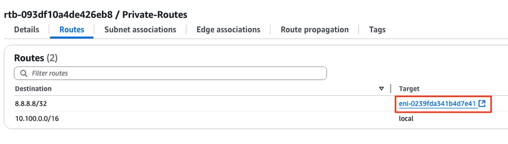
Troubleshoot
These are most of the common points that are often forgotten/misconfigured while recreating the deployment:
- Ensure resources are associated. When creating VPC, Subnets, Interfaces, Route Tables, and so on, many of these are not associated with each other automatically. They have no knowledge of each other.
- Ensure that the Elastic IP and any Private IP is associated with the correct Interfaces, with the right subnets, added to the correct Route Table, connected to the correct router, and the correct VPC and Zone, linked with the IAM Role and security groups.
- Disable Source/Dest check per ENI.
In case you already checked all the points discussed in this section and the issue is still present, please gather these outputs, test the HA failover, if possible, and open a case with Cisco TAC:
show redundancy cloud provider aws <node-id>
debug redundancy cloud all
debug ip http all
Revision History
| Revision | Publish Date | Comments |
|---|---|---|
1.0 |
26-Jun-2025
|
Initial Release |
Contributed by Cisco Engineers
- Felipe SimmondsTechnical Consulting Engineer
 Feedback
Contact Cisco
- Open a Support Case

- (Requires a Cisco Service Contract)