Introduction
This document describes how to create an alarm workflow in order to reprocess exception queue activities in Cisco Enterprise Chat and Email (ECE).
Prerequisites
Note: This is a re-write of the previous CIM document that has been modified for the ECE solution. For a detailed and complete explanation on how to isolate and fix issues related to emails routed to Default Explanation Queue (DEQ) in ECE, refer this document 'Troubleshoot Emails Going to Default Exception Queue in ECE'
Requirements
Cisco recommends that you have knowledge of these topics:
- Cisco Unified Contact Center Enterprise (UCCE) Release 12.6.X
- Cisco Packaged Contact Center Enterprise (PCCE) Release 12.6.X
- Enterprise Chat and Email (ECE) Release 12.6.X
Components Used
The information in this document is based on these software and hardware versions:
- UCCE Version 12.6.2
- ECE Version 12.6.1
The information in this document was created from the devices in a specific lab environment. All of the devices used in this document started with a cleared (default) configuration. If your network is live, ensure that you understand the potential impact of any command.
Background Information
When email activities that do not match the configured delivery exception criteria are sent to the exception queue, it can be necessary to recover those activities so that they can be processed. This can be done manually if a supervisor monitors the exception queue and/or receives notifications when items enter that queue, so that the items can then be selected and transferred to agents for processing. Another way to process these activities is to set up an alarm workflow against the exception queue, and set it to run on a specific schedule or at a single, designated time. With this option, you can allow the system to process the emails through External Agent Assignment Service (EAAS) and Contact Center Enterprise (CCE) again.
Exception Queue Delivery Reasons
There are several reasons for items to be delivered to the exception queue:
- There are no active inbound workflows in the department.
- A workflow faces an error when it processes activities.
- The queue used in a workflow is made inactive. All the activities that come to the inactive queue are routed to the exception queue.
- Emails are bounced-back.
- A NEW_TASK_FAILURE message is returned by CCE.
In this list, only the bounced-back emails are true delivery exceptions that are not able to be retrieved and processed. All the others are potentially able to be recovered.
Alarm Workflow for Notification
By default, an alarm workflow is created within the product, as explained in the Enterprise Chat and Email Administrators Guide to Email and Routing Resources.
https://www.cisco.com/c/dam/en/us/td/docs/voice_ip_comm/cust_contact/contact_center/enterprise_chat_email/enterprise_chat_email_12_6_1/Maintenance/Guide/ece126_userguide_email_administration.pdf
Exception Queue Alarm Workflow
A workflow configured to send notifications when activities are routed to the exception queue because of workflow errors encountered while processing activities. This workflow is active by default and it runs every 12 hours to check if there are any activities with the substatus “Workflow-Error” in the exception queue. If any such activities are found, a notification email with the list of activity IDs is sent. The notification email is sent to the address specified in the “To address: for Notification for services” setting. This is the default configuration of the workflow; however it can be changed to meet your business needs. Although the workflow can be deleted, it is recommended that you do not delete it. If you do not wish to use the workflow, make it inactive."
Configuration
Create a new Alarm Workflow
This section describes how to create an alarm workflow in order to process activities from the exception queue. These steps ensure that activities that were previously directed to the exception queue are processed through integrated queues. There are two important things to remember when you attempt this:
- Which integrated (mapped) queues you want to include
- Which Alias(es) configured within the ECE environment is (are) mapped to each queue
These items are important because the alarm workflow described here uses the alias that the email was sent to originally in order to determine to which queue to redirect the activity. It redirects to the original queue to which the activity would have been directed if the routing failure had not occurred.
In order to create an alarm workflow, choose the new icon in the List pane, and create a name for the workflow.
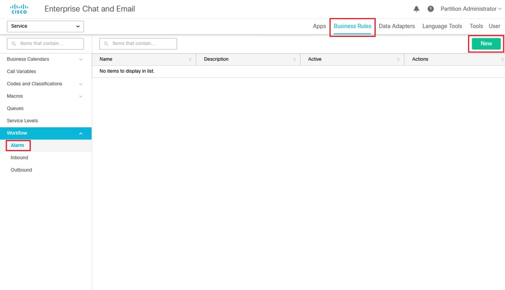 Figure 1a: Create a New Workflow
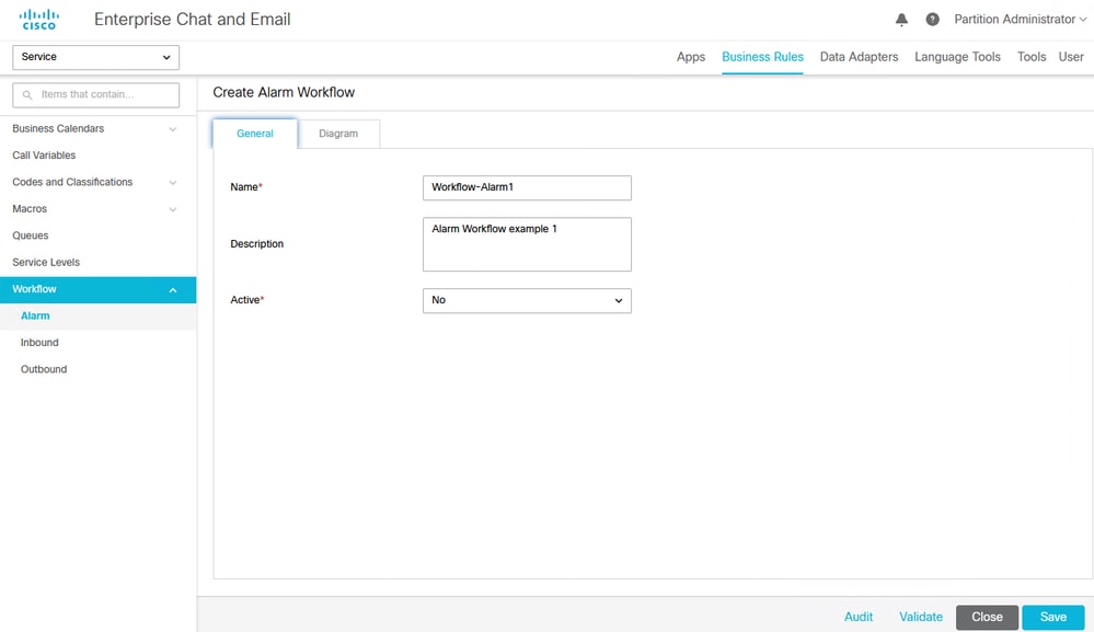 Figure 1b: Create a New Workflow
Add and configure the Start node
Once the workflow is created, it appears in the List pane. In order to add instruction, click the Diagram tab.
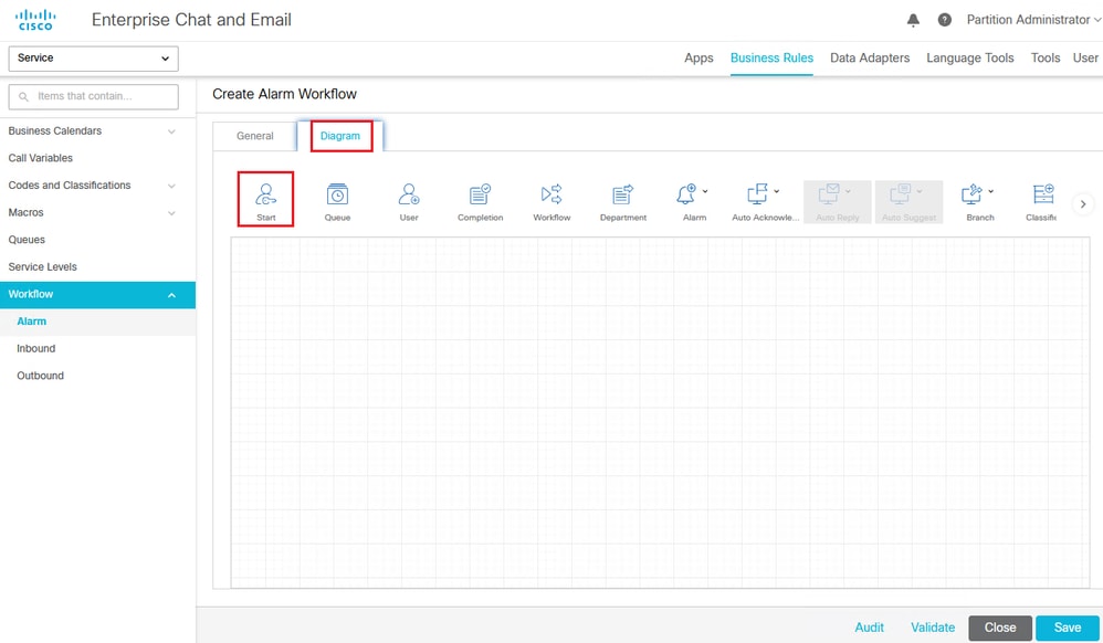 Figure 2: Create a New Workflow Diagram - Drag and drop the Start Node
In order configure the workflow, place a Start node into the diagram. Once you place the node, the Add Start Node dialog box appears. For the purpose of this workflow example, choose Exception_Queue_Service or the name of your specific exception queue.
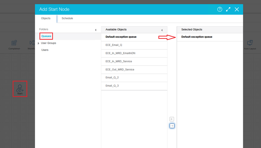 Figure 3: Start Node Configuration
Once you select the exception queue, configure the workflow run schedule. In order to run the workflow each time it is needed, click the radio button next to the The workflow can be run once at option. Then, you can simply change the time you need it to run. This example shows how you would configure it if you had the workflow run once a week at approximately midnight.
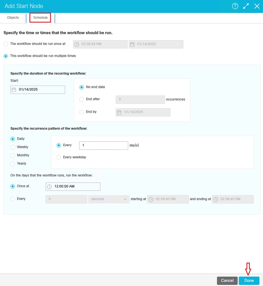 Figure 4: Configure a Start Node Schedule
Add and configure the Queue nodes
Once the start node is in place, configure an alarm node, a branch node, and queue nodes. In order to build a branch node, you first must add all the queues to which the branch node rules direct the activities. It is helpful to create the workflow from right to left. Select the queue node, and place a node for each queue within the diagram of the workflow. Each time you enter the node option, a Select Queue dialog box displays that allows you to choose which queue the node represents.
Note: The example in this document shows a standalone queue. However, the screens and options are the same for integrated queues. This document is intended for processing integrated activities.
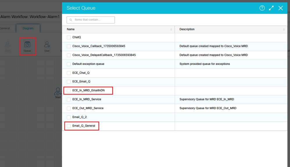 Figure 5a: Select Queue node and in the Queue Dialog Box, select the Queue
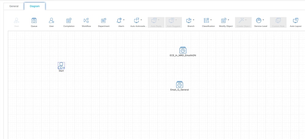 Figure 5b: Queue Nodes with the select Queues
Set up the Branch Node and configure the True/False condition routes
Once the queue nodes are in place, select and place a branch node. Once the branch node is placed, the Branch Rule Configuration dialog box displays.
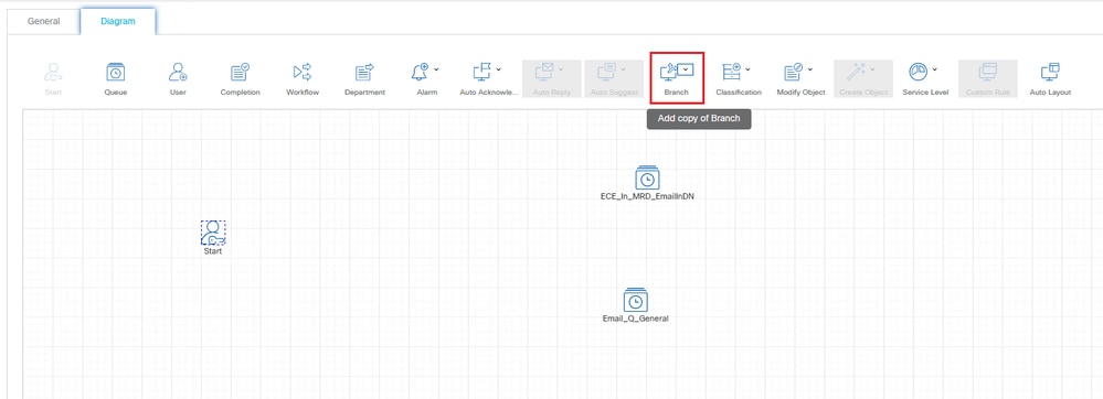 Figure 6: Select the Branch Node
When the Branch Node configuration dialog box displays, you must configure one rule per queue (or branch) to which the node maps.
Note: A branch node can map to other items as well. For example, it can map directly to a specific user. This example maps to integrated queues.
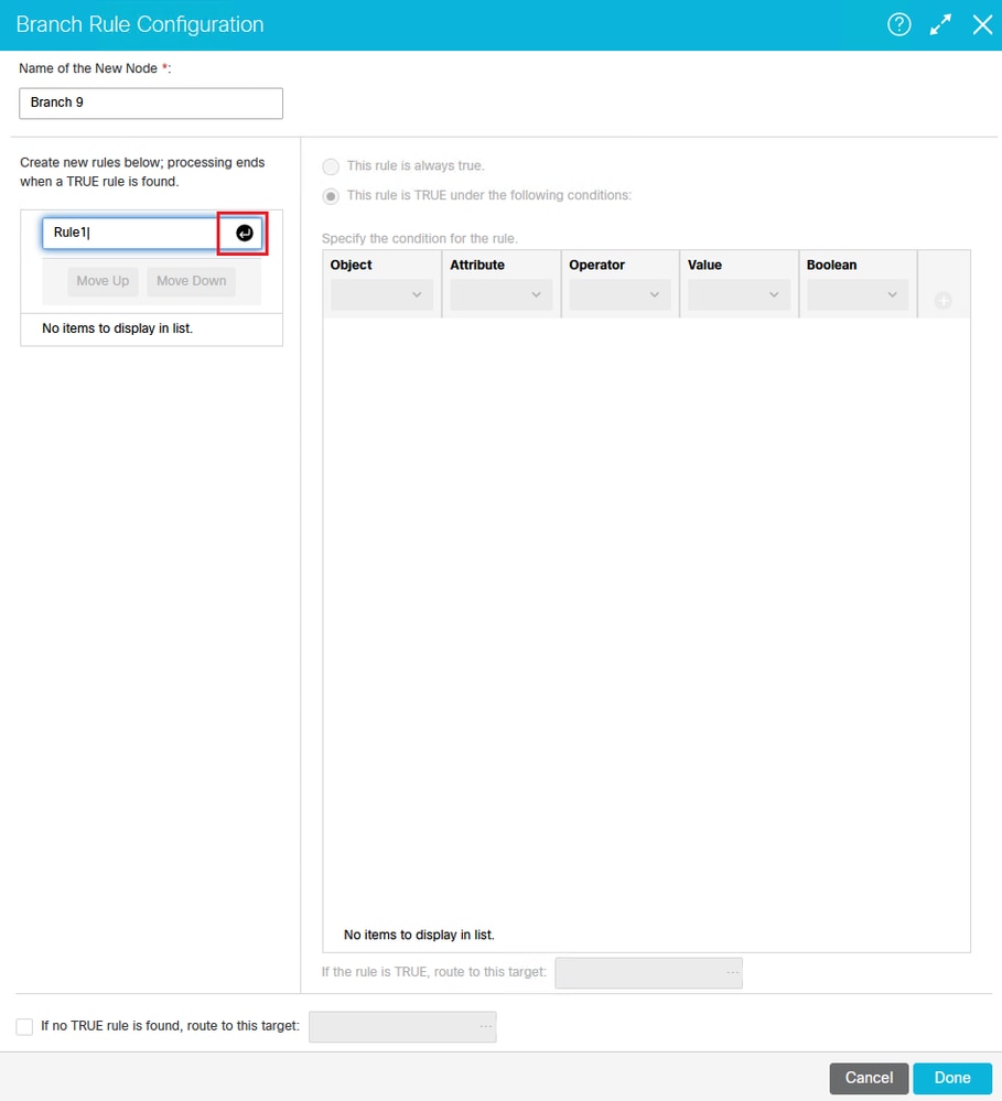 Figure 7: The Branch Rule Configuration Dialog Box
Press Enter once you have named and designated the conditions of your rule.
For this type of alarm workflow, name each of your rules. Once named, highlight the rule, and configure the conditions. The conditions must be set for these items:
- Object: Email
- Attribute: To email address
- Operator: ==
- Value: <alias that the email originally was sent to>*
Note: If you are uncertain of the alias to which the email was originally directed, execute this query: select recv_email_address* from egml_email where activity_id = ####. Replace the #### with the activity ID of a specific email. The email alias indicated here is the one mapped to the queue(s) indicated in the previous step.
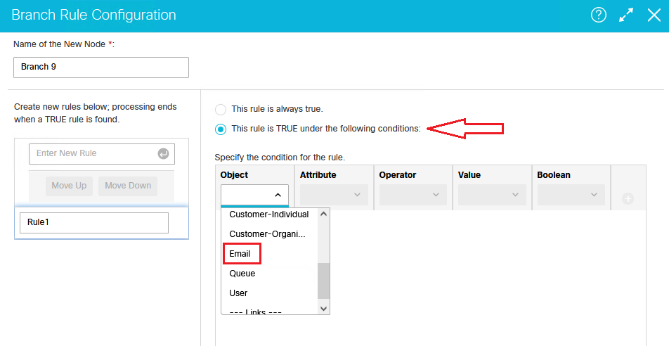 Figure 8a: The Branch Rule Configuration Dialog Box
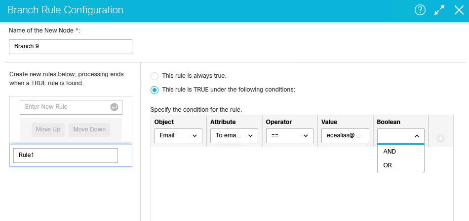 Figure 8b: The Branch Rule Configuration Dialog Box
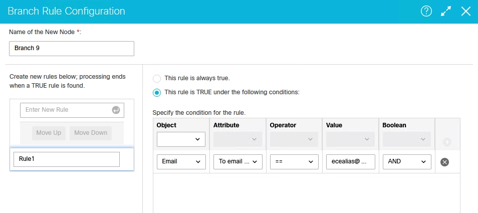 Figure 8c: The Branch Rule Configuration Dialog Box
Configure and map for TRUE and FALSE conditions to queues in the Branch Node Configuration.
Once you have configured the rule, indicate the branch (queue) that is used in the event that the rule is evaluated as true.
Verify that the option at the top that indicates This rule is TRUE under the following conditions is selected, and click the […] button indicated in order to select a target. Once you click that button, the Select Target dialog box appears, which allows you to drill-down to the proper queue for this rule.
Note: If you did not first place the queue nodes in this workflow, this list would be empty. The queues indicated in the workflow determine what displays here.
Once you have set up the TRUE option for your rule, you then must set up a FALSE option. This example indicates the exception queue as this path. However, you can set it up for any other path, another integrated queue, a standalone queue, or a specific User, depending on your business and how you would like to handle these items. This option catches anything that does not match the rules in the branch node.
 Figure 9: Configure and map route targets for TRUE and FALSE conditions
Repeat the rule configuration for each branch, and repeat the exception queue (or false selection) for each one. When you have configured the node completely, the lines that connect the branch node to your queues are completed automatically based on your rule configuration.
Add and configure the Alarm node
The last item you must configure within this workflow is an alarm node. Pull-down and place a new alarm node into the workflow diagram. The Alarm Node Configuration dialog box opens.
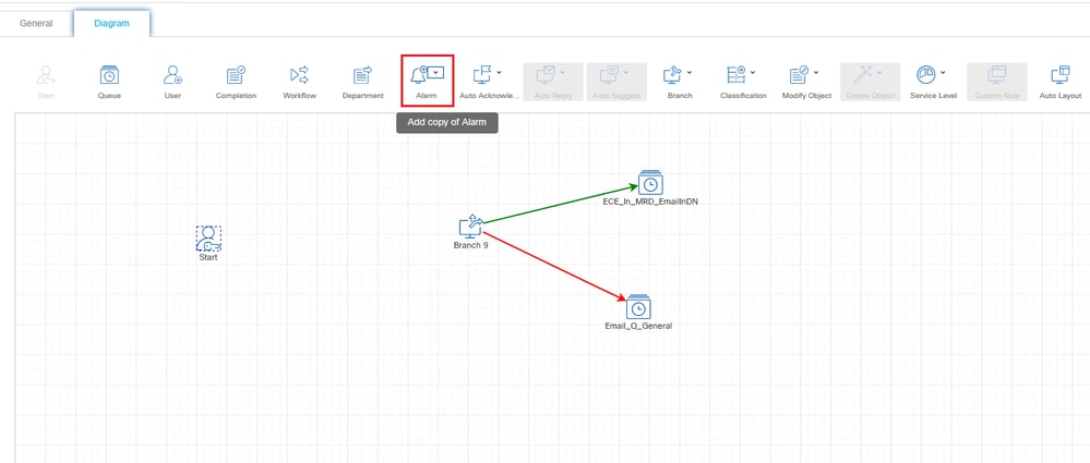 Figure 10a: Select, Place, and Configure an Alarm Node within your Workflow Diagram
On the Alarm Rule Configuration screen, there are two concepts (tabs) that must be configured: a Condition tab and a True tab.
On the Condition tab, you must identify two things: Activity_Status AND Activity_Sub_Status.
Note: In this case, the Boolean expression must be AND because you want both of these conditions to be true.
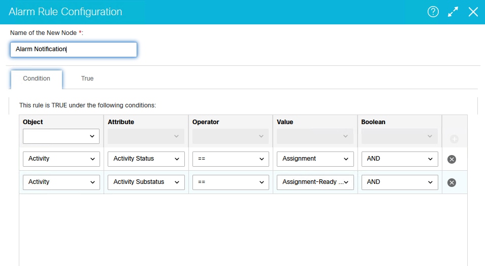 Figure 10b: Configure the Condition Tab on the Alarm Rule Configuration Screen
On the True tab, you must complete these configurations in order to create a filter and select the objects for that filter from within the Basic and Advanced sub-tabs.
On the Action section in the top pane, use the pull-down in order to create a filter with Activity as the object that the filter is run against. When you do this, the bottom pane is then populated with the options to select the criteria for the filter. On this Basic tab, you must define that the subject does not contain the word Undeliverable. This filters any items with an Activity_Sub_Type of 4 and 5, which are emails that are sent to the exception queue because they match a configured delivery exception.
Note: If you do not run this workflow often, or find that there are many emails in the exception queue that require processing, it is advisable to determine another filter option, such as Created On in order to control the number of emails that are processed back into queues. If you run this workflow often, and know that there are a minimal number of emails to process and that no failures have occurred to create large numbers of emails in the exception queue, then this must not be a concern. You need to research the numbers of emails waiting processing, and make a determination based on your environment and the agents available to process these items.
![Figure 10c: Configure the True Option on the [Basic] Tab of the Alarm Rule Configuration Screen](/c/dam/en/us/support/docs/contact-center/enterprise-chat-email-1261/222734-configure-ece-alarm-workflow-to-reproces-15.png) Figure 10c: Configure the True Option on the [Basic] Tab of the Alarm Rule Configuration Screen
Figure 10c: Configure the True Option on the [Basic] Tab of the Alarm Rule Configuration Screen
On the [Advanced] tab, select Email-General for the Activity Sub-Type in order to ensure that only items with an Activity_Sub_Type = 1 are selected. This is a requirement due to the fact that the EAAS process ONLY sends route requests (NEW_TASK Requests) to UCCE for processing if they are of this sub-type. All other sub-types are not processed.
![Figure 10d: Configure the True Option on the [Advanced] Tab of the Alarm Rule Configuration Screen](/c/dam/en/us/support/docs/contact-center/enterprise-chat-email-1261/222734-configure-ece-alarm-workflow-to-reproces-16.png) Figure 10d: Configure the True Option on the [Advanced] Tab of the Alarm Rule Configuration Screen
Figure 10d: Configure the True Option on the [Advanced] Tab of the Alarm Rule Configuration Screen
Once completed, your alarm workflow looks similar to this, depending on the number of queues you have built into it. Again, the queue in this example is named standalone, but this process and document are intended for integrated (mapped) UCCE queues.
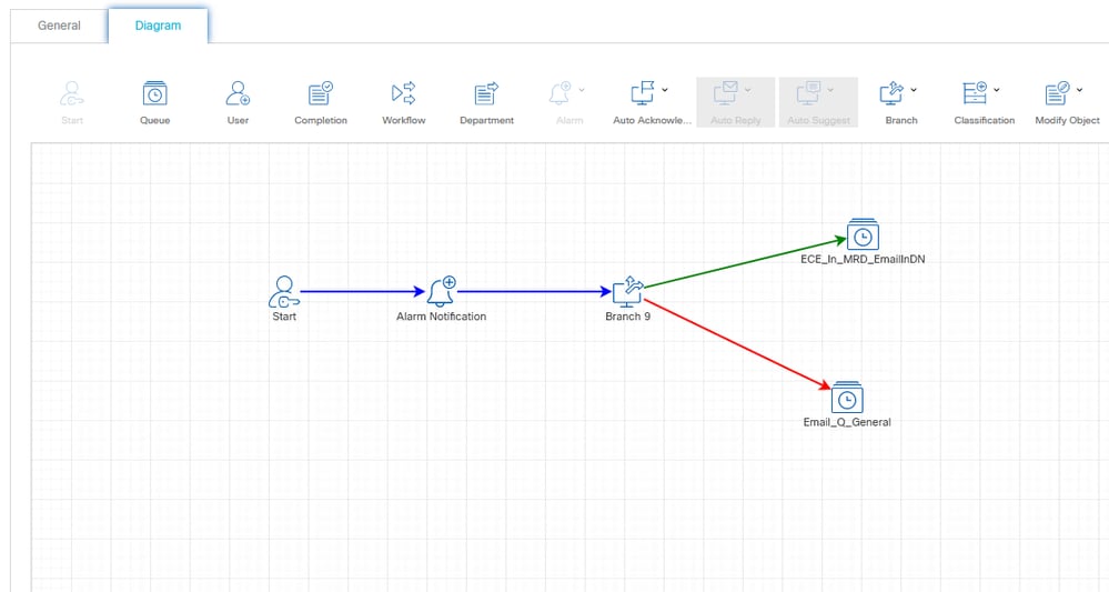 Figure 11: The Completed Alarm Workflow Diagram (Example)
Make the workflow active
The last step in this process is to make the workflow active.
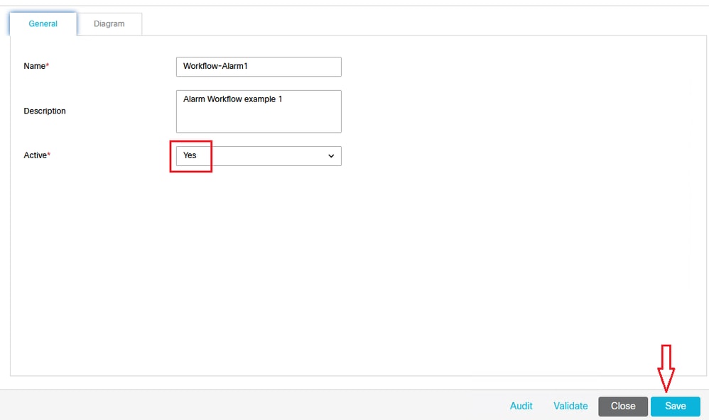 Figure 12: Make the workflow Active
Related Information
 Feedback