Configure Tenant Routed Multicast (TRM) in ACI
Available Languages
Download Options
Bias-Free Language
The documentation set for this product strives to use bias-free language. For the purposes of this documentation set, bias-free is defined as language that does not imply discrimination based on age, disability, gender, racial identity, ethnic identity, sexual orientation, socioeconomic status, and intersectionality. Exceptions may be present in the documentation due to language that is hardcoded in the user interfaces of the product software, language used based on RFP documentation, or language that is used by a referenced third-party product. Learn more about how Cisco is using Inclusive Language.
Contents
Introduction
This document describes how to configure Tenant Routed Multicast (TRM) in ACI to enable Layer 3 multicast routing across VRFs.
Prerequisites
Abbreviations
ACI: Application Centric Infrastructure
VRF: Virtual Routing and Forwarding
BD: Bridge Domain
EPG: EndPoint Group
IGMP: Internet Group Management Protocol
PIM: Protocol-Independent Multicast
ASM: Any Source Multicast
RP: Rendezvous Point
TRM: Tenant Routed Multicast
SVI: Switch Virtual Interface
vPC: virtual Port-channel
Requirements
For this article, it is recommended that you have general knowledge of these topics:
- ACI concepts: Access Policies, Endpoint Learning, Contracts and L3out
- Multicast Protocols: IGMP and PIM
Components Used
This configuration example is based on ACI version 6.0(7e) using second generation Nexus switches N9K-C93180YC-EX running ACI version 16.0(7).
The information in this document was created from the devices in a specific lab environment. All of the devices used in this document started with a cleared (default) configuration. If your network is live, ensure that you understand the potential impact of any command.
Configure
This article focuses on Multicast configuration, so the example assumes you already have Unicast reachability inside and outside the fabric.

Tip: If Unicast reachability is not present between interested parties (Multicast Source, RP, Receivers, and so on) it is very likely that Multicast stream is affected.
The purpose of this configuration example is to first enable Multicast on the Common Tenant/VRF to enable the traffic to come into the Fabric via a L3out and be received on the Receivers on the Common VRF. Then, the second part is to cover how to extend this Multicast stream to a different VRF on the User-define Tenant.
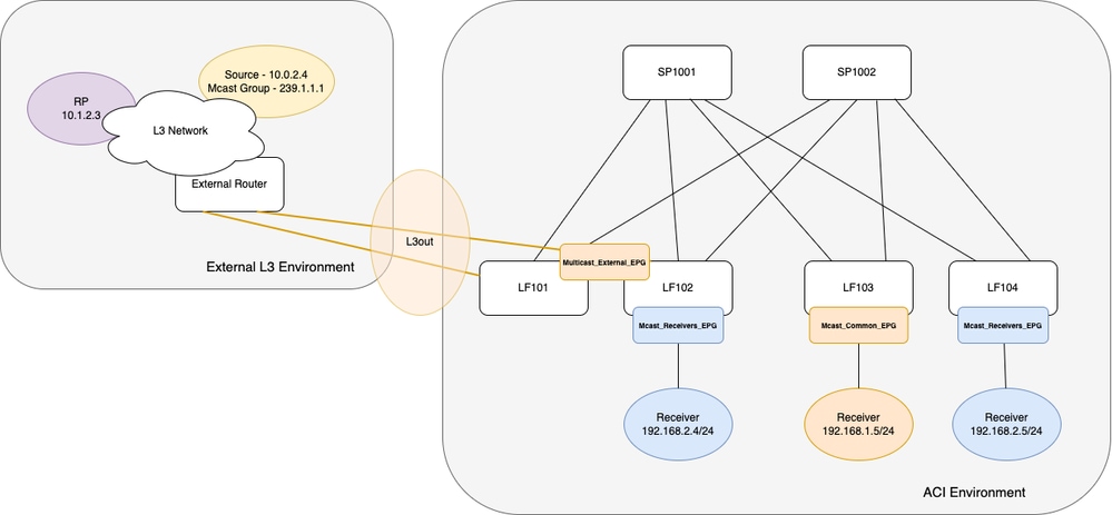
The ACI Fabric is a single POD with 2 Spines and 4 Leaf switches. Two of those four Leaf switches are border-leaf switches that connect to an external NXOS L3 switch via an OSPF L3out. The configuration of the external L3 Network is not covered in this article.
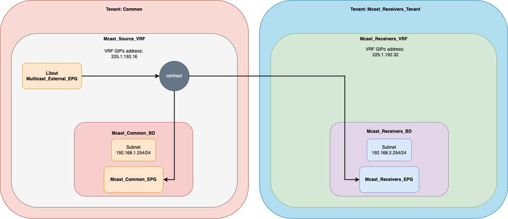
There are 3 endpoints connected inside the Fabric that receive the Multicast traffic. Each endpoint is connected in a different Leaf switch. Logically, there are two Tenants with a VRF in each one. One Tenant is the Common and another one is a User-define Tenant. On the Common Tenant you have the External EPG for the L3out and one Receiver. In The User-define tenant you have two Receivers that are part of the same EPG. For more details refer to the diagrams in the next section.
Network Diagram
Physical Topology
Logical Diagram
Configuration Multicast in Source VRF
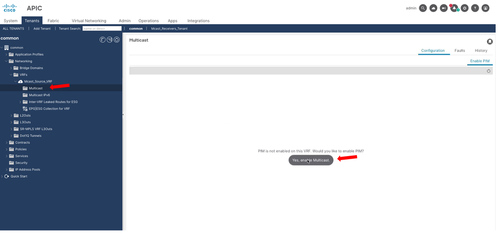
Step 1. Enable Multicast at the VRF level.
Navigate to Tenants > common > Networking > VRFs > Mcast_Source_VRF > Multicast and on the main pane, select Yes, enable Multicast.
Step 2. Add Bridge Domains and L3Out.
Navigate to Tenants > common > Networking > VRFs > Mcast_Source_VRF > Multicast and on the main pane under Interfaces tab you can add the Bridge Domains and L3outs that are participating in the Multicast flow.
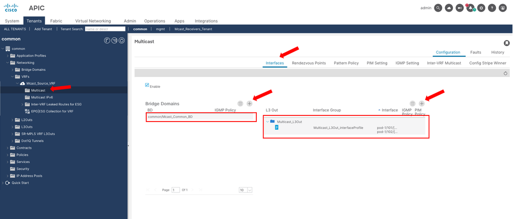
These Bridge Domains and L3outs are local to the VRF.

Caution: On each border-leaf enabled for L3 Multicast, it is required to have a unique IPv4 loopback address that is reachable from the external network. It is used for PIM Hello messages. On this example, the L3out was configured to use the OSPF router-id as a loopback interface.
Step 3. Configure the RP.
Navigate to Tenants > common > Networking > VRFs > Mcast_Source_VRF > Multicast and on the main pane under Rendezvous Points tab you see the options to configure the RP.
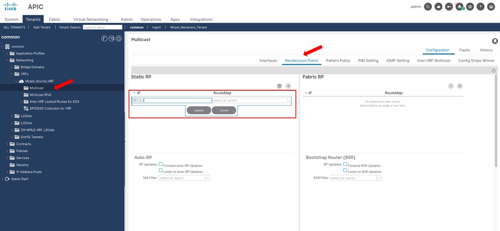

Note: On this example, you are using a Static RP for all the Multicast Groups, so no RouteMap is specified.
After this step, Multicast traffic is now reaching the Receiver 192.168.1.5 on the Common Tenant/VRF.
Configuration Multicast in Receiver VRF – Tenant Routed Multicast
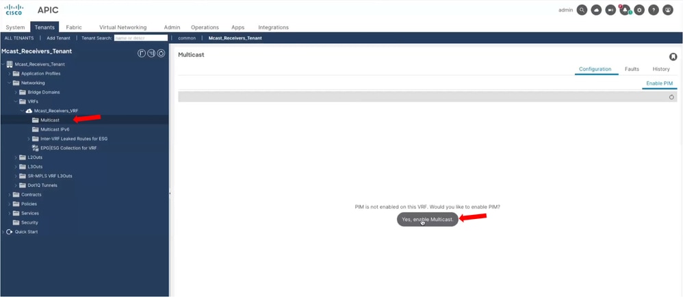
Step 1. Enable Multicast at the VRF level.
Navigate to Tenants > Mcast_Receivers_Tenant > Networking > VRFs > Mcast_Receivers_VRF > Multicast and on the main pane, select Yes, enable Multicast.
Step 2. Add Bridge Domains.
Navigate to Tenants > Mcast_Receivers_Tenant > Networking > VRFs > Mcast_Receivers_VRF > Multicast and on the main pane under Interfaces tab, you can add the Bridge Domains are participating in the Multicast flow.
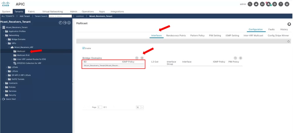
These Bridge Domains are local to the VRF.
Step 3. Configure the RP.
Navigate to Tenants > Mcast_Receivers_Tenant > Networking > VRFs > Mcast_Receivers_VRF > Multicast and on the main pane under Rendezvous Points tab, you see the options to configure the RP.

Note: On this example, you are using a Static RP for all the Multicast Groups, so no RouteMap is specified.
Step 4. Configure Tenant Routed Multicast.
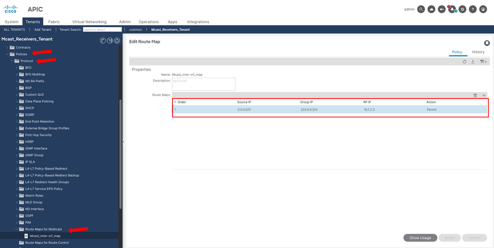
Step 4.1. Create a RouteMap to allow Multicast traffic from Source VRF to Receiver VRF.
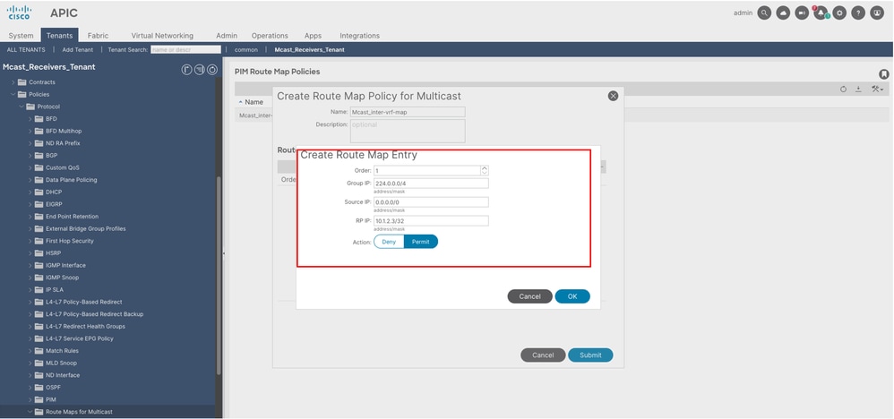
Navigate to Tenants > Mcast_Receivers_Tenant > Policies > Protocol > Route Maps for Multicast, right click to create a new one.
Give a Name and add a Route Map Entry. All the IP values are ranges based on the network mask. Set the Action to Permit to allow the traffic.
Step 4.2. Apply the RouteMap on the Receiver VRF.
Navigate to Tenants > Mcast_Receivers_Tenant > Networking > VRFs > Mcast_Receivers_VRF > Multicast and on the main pane under Inter-VRF Multicast tab, select the Tenant and VRF where the Multicast traffic is getting sourced. Also, select the RouteMap you just created.
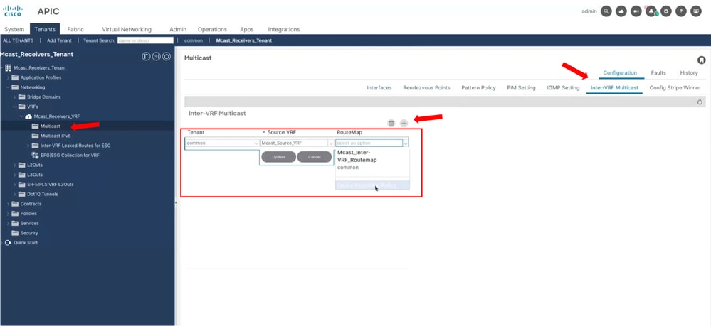
Tip: The creation of the RouteMap can also be done in this step.
After this step, Multicast traffic is now reaching the Receiver 192.168.2.4 on the Common Tenant/VRF. Receiver 192.168.2.5 fails to get the traffic due to a limitation discussed on the next section.
Limitations
In this article, it highlights some important design considerations. For full Guidelines and limitations please refer to:
Cisco APIC Layer 3 Networking Configuration Guide, Release 6.0(x) - Chapter: Tenant Routed Multicast
With TRM, every Leaf that has the receiver VRF needs to have the source VRF deployed. In case it is not present, you get a configuration Fault.
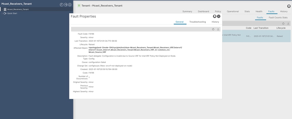
Note: For this reason, Receiver 192.168.2.5 did not receive multicast flow. Because the source VRF is not deployed on LF104. In contrast, Receiver 192.168.2.4 received the multicast flow because LF102 has the source VRF deployed due to the L3out being on that leaf
L3out supports these interfaces for L3 Multicast:
- Routed interfaces
- Routed sub-interfaces
- L3 port-channels
- SVI interfaces (not in vPC)
Note: In this configuration example, SVI interfaces are used, but those are NOT in vPC. Using SVIs over a vPC L3out is not supported for L3 Multicast.
On each border-leaf enabled for L3 Multicast it is required to have a unique IPv4 loopback address that is reachable from the external network. It is used for PIM Hello messages
Note: On this example, the L3out was configured to use the OSPF router-id as a loopback interface.
Verification Steps and Troubleshoot Commands
Active Receivers
Once the Bridge Domain is added to the Multicast Interfaces (Step 2) IGMP is now enabled. If there are endpoints actively requesting multicast traffic, you can see it with next command.
LF102# show ip igmp groups vrf Mcast_Receivers_Tenant:Mcast_Receivers_VRF
Type: S - Static, D - Dynamic, L - Local, T - SSM Translated
IGMP Connected Group Membership for VRF "Mcast_Receivers_Tenant:Mcast_Receivers_VRF"
Group Address        Type   Interface    Uptime               Expires              Last Reporter
239.1.1.1            D      vlan39       3d5h                 00:02:49             192.168.2.4
LF102#
LF103# show ip igmp groups vrf common:Mcast_Source_VRF
Type: S - Static, D - Dynamic, L - Local, T - SSM Translated
IGMP Connected Group Membership for VRF "common:Mcast_Source_VRF"
Group Address Type Interface Uptime Expires Last Reporter
239.1.1.1 D vlan82 05:22:51 00:03:51 192.168.1.5
LF103#LF104# show ip igmp groups vrf Mcast_Receivers_Tenant:Mcast_Receivers_VRF
Type: S - Static, D - Dynamic, L - Local, T - SSM Translated
IGMP Connected Group Membership for VRF "Mcast_Receivers_Tenant:Mcast_Receivers_VRF"
Group Address Type Interface Uptime Expires Last Reporter
239.1.1.1 D vlan73 3d5h 00:02:36 192.168.2.5
LF104# RP IP Address and Group Deployed
Once the RP IP is configured (Step 3) you can validate it is deployed correctly in each Leaf on its respective VRF.
LF102# show ip pim rp vrf common:Mcast_Source_VRF

PIM RP Status Information for VRF:"common:Mcast_Source_VRF"
BSR disabled
Auto-RP disabled

RP: 10.1.2.3, uptime: 3d5h, expires: never
  priority: 0, RP-source:  (local) group-map: None, group ranges:
      224.0.0.0/4

LF102# show ip pim rp vrf Mcast_Receivers_Tenant:Mcast_Receivers_VRF

PIM RP Status Information for VRF:"Mcast_Receivers_Tenant:Mcast_Receivers_VRF"
BSR disabled
Auto-RP disabled

RP: 10.1.2.3, uptime: 3d5h, expires: never
  priority: 0, RP-source:  (local) group-map: None, group ranges:
      224.0.0.0/4

LF102#
PIM Adjacency
Once the L3out is added to the Multicast Interfaces (Step 2) PIM is now enabled. Verify that PIM neighborship over the L3out is formed. You can see as well that the border-leaf switches from PIM neighborship between them over the fabric.
LF101# show ip pim neighbor vrf common:Mcast_Source_VRF

PIM Neighbor information for Dom:common:Mcast_Source_VRF
Neighbor             Interface            Uptime               Expires              DRPriority Bidir      BFDState
10.0.0.102/32        tunnel17             3d13h                00:01:44             1          no         n/a
10.0.1.4/32          vlan39               3d5h                 00:01:39             1          yes        n/a
LF101#
LF102# show ip pim neighbor vrf common:Mcast_Source_VRF
PIM Neighbor information for Dom:common:Mcast_Source_VRF
Neighbor Interface Uptime Expires DRPriority Bidir BFDState
10.0.0.101/32 tunnel19 3d13h 00:01:25 1 no n/a
10.0.2.4/32 vlan42 3d5h 00:01:22 1 yes n/a
LF102# Stripe-Winner
When you have multiple border-leaf switches with PIM enable, one is elected as the Stripe Winner. The Stripe Winner is responsible to send the PIM join/prune messages to external sources/RP. Additionally, it is responsible as well to forward the traffic into the Fabric. Is possible to have more than one Stripe-Winner, but that is not covered in this example.
With the next command you can check which border-leaf is elected as the Stripe Winner
LF101# show ip pim internal stripe-winner 239.1.1.1 vrf common:Mcast_Source_VRF
PIM Stripe Winner info for VRF "common:Mcast_Source_VRF" (BL count: 2)
(*, 239.1.1.1)
BLs:
Group hash 1656089684 VNID 2326529
10.0.0.101  hash: 277847025 (local)
      10.0.0.102  hash: 1440909112
Winner: 10.0.0.102 best_hash: 1440909112

Configured Stripe Winner info for VRF "common:Mcast_Source_VRF"

Not found
LF101#
LF102# show ip pim internal stripe-winner 239.1.1.1 vrf common:Mcast_Source_VRF
PIM Stripe Winner info for VRF "common:Mcast_Source_VRF" (BL count: 2)
(*, 239.1.1.1)
BLs:
Group hash 1656089684 VNID 2326529
10.0.0.102 hash: 1440909112 (local)
10.0.0.101 hash: 277847025
Winner: 10.0.0.102 best_hash: 1440909112
Configured Stripe Winner info for VRF "common:Mcast_Source_VRF"
Not found
LF102# Mroute
Checking the Mroutes is useful for many things.
- You can see if a (S,G) entry exists, meaning traffic from specific source is being received.
- Check the incoming interface and validate that is the expected path towards the source and RP.
- Check the Outgoing interface list to see where the traffic is forwarded and how it got that entry, via IGMP or PIM.
- On border-leaf switches you can also see who is the Stripe Winner. It has the Mroutes, and non-elected border-leaf do not.
LF101# show ip mroute 239.1.1.1 vrf common:Mcast_Source_VRF
IP Multicast Routing Table for VRF "common:Mcast_Source_VRF"

Group not found

LF101#
LF102# show ip mroute 239.1.1.1 vrf common:Mcast_Source_VRF
IP Multicast Routing Table for VRF "common:Mcast_Source_VRF"
(*, 239.1.1.1/32), uptime: 3d05h, ngmvpn ip pim mrib
Incoming interface: Vlan42, RPF nbr: 10.0.2.4
Outgoing interface list: (count: 1) (Fabric OIF)
Tunnel19, uptime: 3d05h, ngmvpn
Extranet receiver list: (vrf count: 1, OIF count: 1)
Extranet receiver in vrf Mcast_Receivers_Tenant:Mcast_Receivers_VRF:
(*, 239.1.1.1/32) OIF count: 1
(10.0.2.4/32, 239.1.1.1/32), uptime: 01:32:02, ip mrib pim ngmvpn
Incoming interface: Vlan42, RPF nbr: 10.0.2.4
Outgoing interface list: (count: 1) (Fabric OIF)
Tunnel19, uptime: 01:32:02, mrib, ngmvpn
Extranet receiver list: (vrf count: 1, OIF count: 1)
Extranet receiver in vrf Mcast_Receivers_Tenant:Mcast_Receivers_VRF:
(10.0.2.4/32, 239.1.1.1/32) OIF count: 1
LF102# LF102# show ip mroute 239.1.1.1 vrf Mcast_Receivers_Tenant:Mcast_Receivers_VRF
IP Multicast Routing Table for VRF "Mcast_Receivers_Tenant:Mcast_Receivers_VRF"
(*, 239.1.1.1/32), uptime: 3d05h, igmp ip pim
Incoming interface: Vlan42, RPF nbr: 10.0.2.4
Outgoing interface list: (count: 1)
Vlan39, uptime: 3d05h, igmp
(10.0.2.4/32, 239.1.1.1/32), uptime: 01:33:19, pim mrib ip
Incoming interface: Vlan42, RPF nbr: 10.0.2.4
Outgoing interface list: (count: 1)
Vlan39, uptime: 01:33:19, mrib
LF102# LF103# show ip mroute 239.1.1.1 vrf common:Mcast_Source_VRF
IP Multicast Routing Table for VRF "common:Mcast_Source_VRF"
(*, 239.1.1.1/32), uptime: 05:38:05, igmp ip pim
Incoming interface: Tunnel19, RPF nbr: 10.2.184.64
Outgoing interface list: (count: 1)
Vlan82, uptime: 05:38:05, igmp
LF103# LF104# show ip mroute 239.1.1.1 vrf Mcast_Receivers_Tenant:Mcast_Receivers_VRF
IP Multicast Routing Table for VRF "Mcast_Receivers_Tenant:Mcast_Receivers_VRF"
(*, 239.1.1.1/32), uptime: 3d05h, igmp ip pim
Incoming interface: Tunnel19, RPF nbr: 10.2.184.67
Outgoing interface list: (count: 1)
Vlan73, uptime: 3d05h, igmp
LF104#
Multicast Forwarding Inside the Fabric
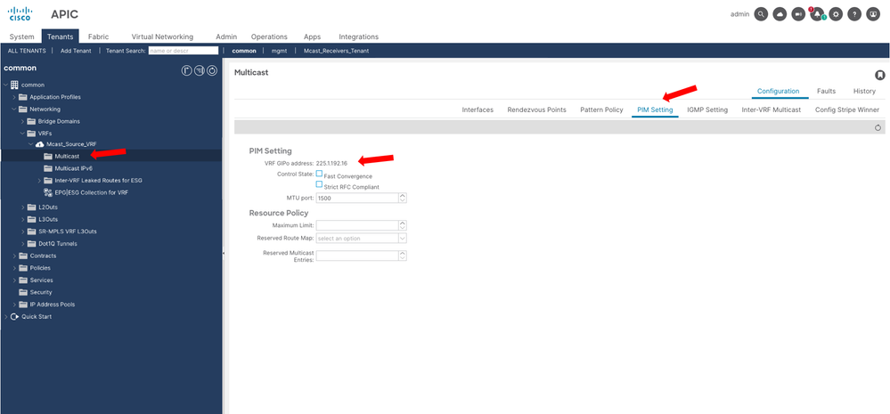
Inside the ACI Fabric to handle BUM (Broadcast, Unknown Unicast and Multicast) traffic, a VXLAN tunnel is created with destination IP being a Multicast IP, this IP is called GIPo address. Each Bridge Domain (for L2 traffic) or VRF (for L3 traffic) has a GIPo address automatically assigned to it.
This GIPo address can be consulted on the APIC GUI. Navigate to Tenants > common > Networking > VRFs > Mcast_Source_VRF > Multicast and on the main pane under PIM Settings tab, you see the VRF GIPo address used in this example is 225.1.192.16.
On the Spine switches you can see to which Leaf switches the VRF is deployed, because the GIPo address mroute list the interfaces of each Leaf. Due to this, if the source VRF is not deployed on a specific Leaf, TRM fails to extend the Multicast flow to the receiver VRF. On this output, note how LF104 is not part of the OIL for the GIPo.
Note: It is possible that the VRF GIPo can be installed on a leaf where the VRF is not deployed, to be able from the complete FTAG tree. That Leaf is called a Transit Leaf. The topic of FTAG tree is not covered on this article to keep the focus on TRM configuration.
SP1001# show ip mroute 225.1.192.16 vrf overlay-1
IP Multicast Routing Table for VRF "overlay-1"

(*, 225.1.192.16/32), uptime: 5d05h, isis
  Incoming interface: Null, RPF nbr: 0.0.0.0
  Outgoing interface list: (count: 4)
    Ethernet1/1.1, uptime: 00:01:19
    Ethernet1/11.39, uptime: 06:01:14
    Ethernet1/2.13, uptime: 5d05h

SP1001# show lldp neighbors
Capability codes:
  (R) Router, (B) Bridge, (T) Telephone, (C) DOCSIS Cable Device
  (W) WLAN Access Point, (P) Repeater, (S) Station, (O) Other
Device ID            Local Intf      Hold-time  Capability  Port ID
LF101                Eth1/1          120        BR          Eth1/52
LF102                Eth1/2          120        BR          Eth1/52
LF103                Eth1/11         120        BR          Eth1/52
LF501                Eth1/13         120        BR          Eth1/54
LF401                Eth1/15         120        BR          Eth1/53
LF402                Eth1/16         120        BR          Eth1/53
LF104                Eth1/31         120        BR          Eth1/52
Related Information
Cisco APIC Layer 3 Networking Configuration Guide, Release 6.0(x) - Chapter: Tenant Routed Multicast
Revision History
| Revision | Publish Date | Comments |
|---|---|---|
1.0 |
29-Jan-2025
|
Initial Release |
Contributed by Cisco Engineers
- Victor Manuel Menchaca AlanisTechnical Consulting Engineer
 Feedback
Contact Cisco
- Open a Support Case

- (Requires a Cisco Service Contract)