Cisco Embedded Wireless Controller on Catalyst Switches (Non-SD-Access) Deployment Guide
Available Languages
Bias-Free Language
The documentation set for this product strives to use bias-free language. For the purposes of this documentation set, bias-free is defined as language that does not imply discrimination based on age, disability, gender, racial identity, ethnic identity, sexual orientation, socioeconomic status, and intersectionality. Exceptions may be present in the documentation due to language that is hardcoded in the user interfaces of the product software, language used based on RFP documentation, or language that is used by a referenced third-party product. Learn more about how Cisco is using Inclusive Language.
As part of mode consolidation Embedded Wireless on Catalyst 9000 Series Switch (non-SDA) using WebUI will be End of Support (Q3FY21) with no additional feature development or code changes and 17.3.x is the last supported release.
The supported workflow is shown in this deployment guide.
This mode has limited ability to customize configuration or assist deployments for Brownfield migration. Also, it does not provide a centralized management orchestrator to manage the infrastructure.
For customers looking for flexible architecture to suit their needs, we recommend the following options:
● Option 1 : Embedded Wireless on an Access Point (up to 100 APs)
● Option 2 : Embedded Wireless on Catalyst 9000 Series switches using DNAC (SD-Access) (up to 200 APs)
● Option 3 : 9800-L (or 9800-CL) locally on branches or in FlexConnect mode (up to 500 APs)
Please note: There are no changes to the support for Embedded Wireless on Catalyst 9k (SD-Access) using DNAC.
For any further questions regarding this mode, please reach out to: ask-ewc-nonsda-pm-tm@cisco.com
Among small to medium-sized customers, many are looking to deploy a wireless network in their branch or single-site offices while optimizing their operational expenses. Many of these customers are heavily invested in the Cisco® Catalyst® 9000 switching platform and want to maximize the value of the platform, leveraging the reliability and programmability of the Cisco IOS® XE software. They are looking for a solution that enables them to easily deploy access points in their network without having to manage another device at their sites. In addition, the solution must provide secure and resilient access for all employees and guests at the site while also giving the customer an option to expand their wireless capabilities as they grow.
The Cisco Embedded Wireless Controller (EWC) on Catalyst 9000 Switches (non-SD-Access) using WebUI combines the best-in-class performance of the Catalyst 9000 switching family and the Catalyst 9800 Series wireless controllers in a single box. Through the switch’s WebUI, customers can easily deploy their corporate and guest WLAN for their site. Additionally, the EWC provides a great migration strategy for customers that have already purchased Catalyst 9000 family switches, allowing them to enable wireless capabilities without the need for an additional standalone controller.
This solution helps customers reduce complexity, optimize IT, and lower operational costs by leveraging the existing expertise of their network administrators on Cisco IOS XE switches to deploy wireless solutions, regardless of where they are in the intent-based networking journey.
This guide covers the deployment of the following network capabilities:
● Enabling the EWC on Catalyst 9000 Switches
● Examples of WLAN configurations for both corporate and guest networks
● Common Quality-of-Service (QoS) and security policies
● Onboarding and provisioning of Access Points (APs)
Supported scale per switch
The supported number of access points and clients per switch or switch stack is shown in Table 1. For a single site, there can be two separate, active embedded controller instances on separate Catalyst 9000 switches. In such cases, the scale of APs and clients will double.
Table 1. AP and client scale for the EWC on Catalyst 9000 switches (non-SD-Access)
| Switch model |
AP scale |
Client scale |
| 9300L models |
50 |
1000 |
| 9300 Series 9400 Series 9500 and 9500H Series |
200 |
4000 |
Scale in comparison to other models
The scale in comparison to some of the other WLC models, specifically the Cisco Software-Defined Access (SD-Access) enabled models and the EWC on Catalyst APs, is shown in Table 2 below. For a more comprehensive comparison, please see: https://www.cisco.com/c/dam/en/us/products/se/2020/4/Business_Unit/WLC_Comparison.pdf
Table 2. Scale comparison of the EWC on Catalyst 9000 Switches (non-SD-Access) using WebUI to the EWC on Catalyst APs and SD-Access enabled WLCs
|
|
Catalyst 9800-40 |
Catalyst 9800-L |
EWC on Catalyst 9000 Switches (SD-Access) |
EWC on Catalyst APs |
EWC on Catalyst 9000 Switches (non-SD-Access) |
| Scale |
|||||
| Access points |
2000 |
5001 |
2002 |
1003 |
2002 |
| Clients |
32,000 |
10,0001 |
40002 |
20003 |
40002 |
| WLANs |
4096 |
4096 |
64 |
16 |
64 |
| Management |
|||||
| AP deployment modes |
Local, Flex, Fabric |
Local, Flex, Fabric |
Fabric |
Flex with local switching |
Fabric4 |
| Multisite deployments |
X |
X |
X5 |
X |
|
| SD-Access fabric deployments |
X |
X |
X |
|
|
| Integrated WebUI |
X |
X |
X |
X |
X |
| Cisco DNA Center |
X |
X |
X |
X |
|
| Cisco DNA Center Cloud |
|
|
|
X |
|
| Supported access points |
|||||
| Catalyst 9100 802.11ax |
X |
X |
X |
X |
X |
| Aironet® 802.11ac Wave 2 |
X |
X |
X |
X |
X |
| Aironet 802.11ac Wave 1 |
X |
X |
X |
|
|
Supported matrix
The features that are supported on the EWC on Catalyst 9000 Switches (non-SD-Access) using WebUI is shown in Table 3.
Table 3. Supported features on the EWC on Catalyst 9000 switches (non-SD-Access) using WebUI.
|
|
Features |
| Full stack health visibility |
WebUI Programmability (NETCONF+ YANG) |
| AP modes |
WGB mode Monitor mode |
| Infrastructure |
Pre-image download Client IPv6 DHCP Option 82 |
| Security and authentication |
WPA-PSK 802.1X (WPA2/AES) 802.1X (WPA2/TKIP) WPA3 Identity PSK Multi-PSK on single SSID Internal Webauth External Webauth Central Webauth DNS pre-auth ACL WEP 802.11r 802.11k 802.11v BSS transition 802.11v DMS PMF (802.11w) TACACS Radius server per WLAN Backup RADIUS servers Cisco Centralized Key Management User idle timeout per WLAN |
| Services |
AVC-mark, drop, RL AAA override-VNID AAA override: ACL, QoS AAA override – session timeout AAA override of AVC profile AAA override BW contract QoS Local profiling RADIUS profiling Per-user bandwidth contract Per-SSID bandwidth contract Multicast CAC, WMM policy Adaptive 11r Fastlane MAB MAC authentication Rogue detection Passive clients BYOD, NAC RADIUS, CWA, LWA |
| RF and radio |
RRM-DCA, TPC, CHDM FRA Band Select Load balancing RF profiles XOR Optimized roaming RX-SOP DFS DBS Off-channel scanning Off-channel scan defer ClientLink A-MSDU/A-MPDU aggregation config per priority ATF UL OFDMA DL OFDMA UL MU MIMO DL MU MIMO TWT BSS coloring |
| Resiliency |
High availability: SSO1 High availability: N+1 Hot/cold patching AP service pack (APSP) AP device pack (APDP) |
| Segmentation |
Up to 4 segments No SGT-based segmentation |
To use the EWC on the switch, the following components are needed:
Cisco Catalyst 9000 switch family
9300, 9300L, 9400, 9500, or 9500H Series
Software requirements:
● Release 17.3 with the wireless sub-package installed
● Management IP address to access the WebUI
● Loopback0 IP address
Note: EWC configuration is supported only via the WebUI.
Cisco Catalyst access points
All Catalyst 9100 APs
Cisco Aironet access points
Indoor Wave 2: Aironet 1800, 2800, 3800, or 4800 Series APs
Outdoor Wave 2 (local mode only): 1540 or 1560 Series
Licensing
Both the switches and APs require Cisco DNA Advantage licenses.
The EWC can be deployed in the following ways:
● Single switch
● High Availability Stateful Switchover (HA SSO)
● N+1 redundancy
Single switch deployment
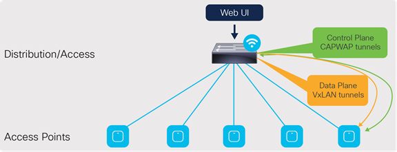
Single switch design
At a minimum, the EWC can be deployed on a single switch with all the APs connected directly into it. However, this is not recommended, as in the event of a switch failure, the entire wireless network will go down until the switch is recovered or replaced.
The APs can also be connected to an external edge node, which is then connected to the EWC. The connections between the EWC and the external edge nodes as well as between any intermediate switches need to be Layer 2 connections with the appropriate VLAN trunking between them. As discussed later in the “Onboard and provision wireless access points - Setting up network topology” section, the APs discover and join the EWC via the AP onboarding VLAN. The VLAN tagging between the AP and EWC needs to be preserved across the multiple switches. Otherwise, the AP will fail to join the EWC.
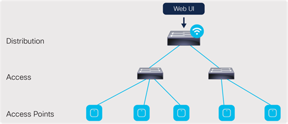
Connection via an external edge node
For a single site, there can be two separate embedded controller instances on separate Catalyst 9000 switches. In such cases, the scale for both the APs and the clients will double.
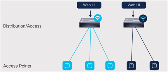
A single site with two controller instances
High Availability Stateful Switchover (HA SSO)
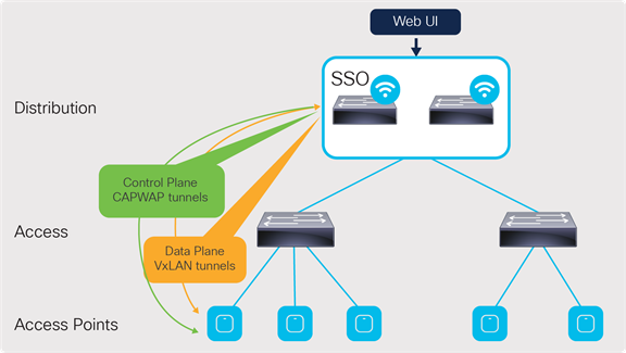
HA SSO design
This is the recommended deployment model for the embedded wireless controller.
In this deployment, all the control plane-related information is synchronized between the active and standby units.
For the switches, HA SSO will be implemented by:
● Catalyst 9300L Models: StackWise®-320
● Catalyst 9300 Series: StackWise-480
● Catalyst 9400 Series: Dual supervisor
To the APs and network, the stack of switches for the EWC will appear logically as a single controller. The active controller centrally manages all the control and management communication. The control plane data is synchronized between the two switches through the StackWise ports.
The APs connected to the stack also have their Control and Provisioning of Wireless Access Points (CAPWAP) states synced between the active and hot-standby controllers on the switches. In the event that the active controller or switch fails, all the APs will switch over to the hot-standby rather than go into discovery mode to join the standby controller. This enables little to no downtime in the event of a failure.
APs can be directly connected to an individual switch in the stack, but this is not recommended. They should be aggregated through an intermediate switch, and the intermediate switch will connect to both switches in the stack. This prevents the APs from going down in the event that one of the switches in the stack fails.
Note: HA SSO is not supported with the Catalyst 9400 Series StackWise Virtual setups, nor with the Catalyst 9500 or 9500H Series
Catalyst 9300 Series StackWise configuration: https://www.cisco.com/c/en/us/td/docs/switches/lan/catalyst9300/software/release/17-3/configuration_guide/stck_mgr_ha/b_173_stck_mgr_ha_9300_cg/managing_switch_stacks.html#concept_j2w_shc_31b
Catalyst 9400 Series dual supervisor installation: https://www.cisco.com/c/en/us/td/docs/switches/lan/catalyst9400/hardware/sup_install/b-c9400-sup-note.html
N+1 redundancy
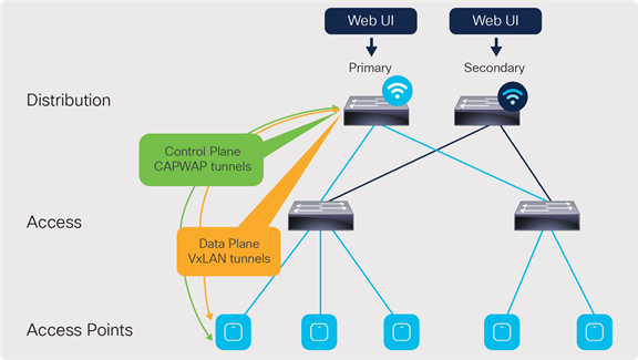
N+1 redundancy design
In the N+1 deployment model, the two embedded controllers are independent of each other and do not sync configuration data across any interface. Each of the EWCs will need to be managed individually. Because of this, the redundancy method is not stateful, and so the CAPWAP state of the APs will restart in the event of a failure. The APs will go into discovery mode to join the backup controller, resulting in longer failover times.
To minimize the failover time, we recommend having the same configuration, in terms of WLANs, profiles, mobility group, policy, RF, and site tags, as well as AP-to-tag mappings, on the primary and secondary controllers.
The EWCs can be deployed in two N+1 configurations:
● One controller will be the primary for all the access points, and the other is the secondary.
● One controller will be the primary for some of the APs, and the other controller will be the primary for the remaining APs. The controllers will be the secondary for each other.
In either case, the scale for the number of APs and clients stays the same as shown earlier in Table 1. The only change is in which controller will be the primary for the APs.
The N+1 design can also be configured alongside the HA SSO redundancy method. The same two deployment configurations apply to this type of design. Figure 6 shows an example topology in which one SSO pair will be the primary controller while another SSO pair will be the secondary.
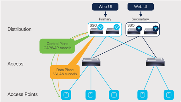
N+1 redundancy with HA SSO design
For more information, please see the Catalyst 9800 Series N+1 configuration guide: https://www.cisco.com/c/en/us/td/docs/wireless/controller/9800/17-3/config-guide/b_wl_17_3_cg/m_vewlc_high_availability.html#task_k2c_nps_xfb
Installing the wireless sub-package
To enable the non-SD-Access EWC on a Catalyst 9000 switch, the switch needs to have at least the Cisco IOS XE Release 17.3.1 image installed, along with the corresponding wireless sub-package. Please note that the base Cisco IOS XE image and wireless sub-package always need to be the same exact release.
The latest wireless sub-package can be found at software.cisco.com.
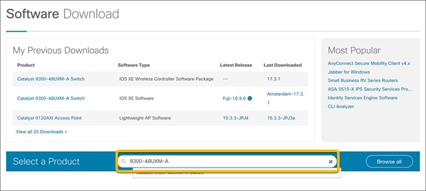
Once on the webpage, go to Software Download.
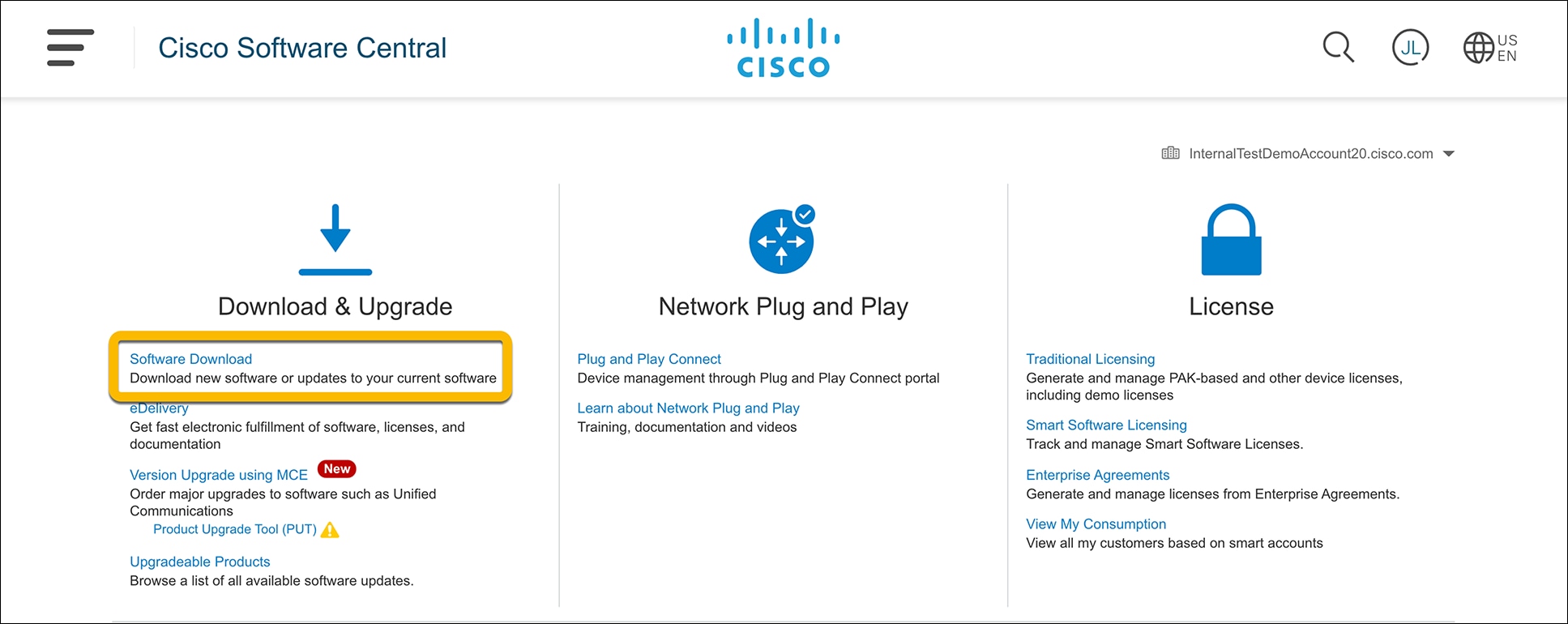
Enter the switch model into the search bar and click Enter.
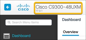
● Note: The switch model can be found in the top bar of the WebUI for the switch.
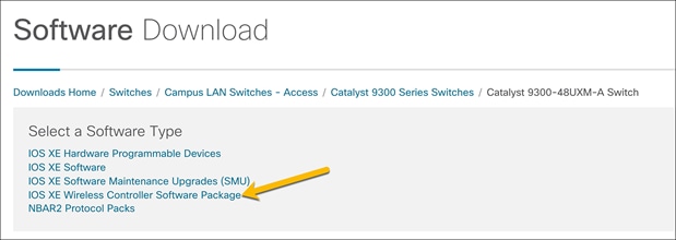
For the Software Type, select IOS XE Wireless Controller Software Package.
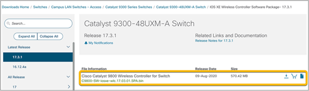
Select and download the sub-package version that matches the Cisco IOS XE image installed on the switch.
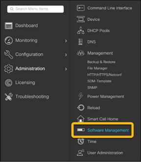
Go to the switch’s WebUI and navigate to Administration Ò Software Management.
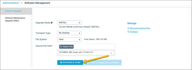
In the Software Upgrade section, choose the preferred method to upload the wireless sub-package to the switch and click Download and Install.
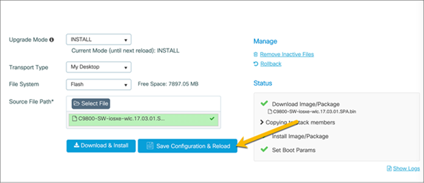
Once the sub-package is finished installing, the switch will need to be reloaded for the sub-package to be applied. Click Save Configuration & Reload.
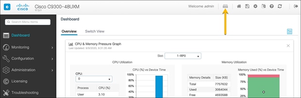
Once the switch is reloaded, log back into the WebUI and click the wireless icon in the dashboard.
In the resulting window, choose Yes to enable the wireless controller.
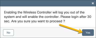
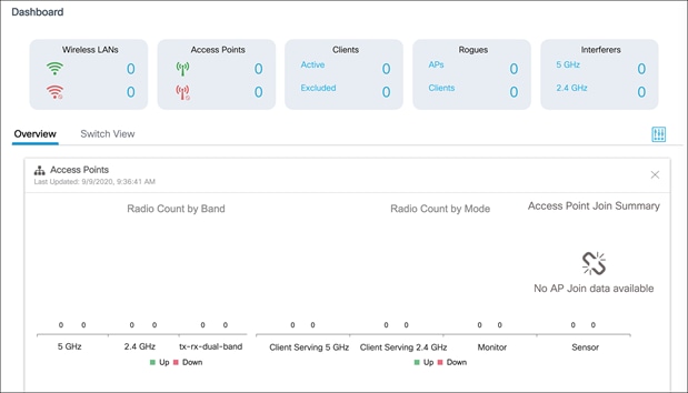
After 30 seconds, log back in to the WebUI. Notice that the homepage dashboard now shows readouts for a wireless LAN controller. The switch is now ready to be configured for all the necessary WLANs in the network.
When deploying the EWC, ensure that the following options have been configured. This will allow for a smoother process when creating the WLANs for the site.
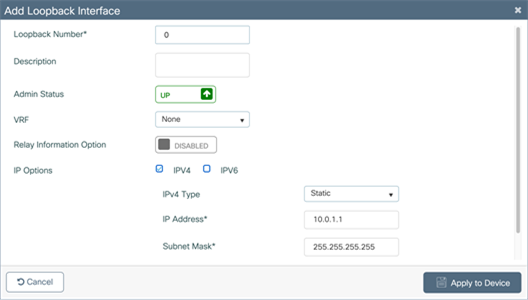
Verify loopback interface
Interface Loopback0 is required to enable the EWC. Since the EWC operates in Fabric Mode, the Loopback0 address serves as the routing locator of the device. If it is not configured, you will be prompted to create it.
Note: The Loopback interface must be Loopback0. If a different Loopback interface is used, there will be errors in deploying the EWC.
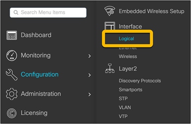
Navigate to Configuration Ò Interface Ò Logical and go to the Loopback tab.
Verify that the Loopback0 address has been configured.
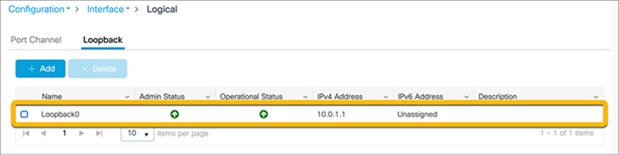
If it is not configured, click the Add button and configure the Loopback0 interface. The Loopback0 IP address can be any IP address that is reachable within the network.
Click Apply to Device.
Configure Virtual Route Forwarding (VRF)
To segment the network, the EWC supports up to four VRFs. This allows the IP networks in separate VRFs to be isolated from each other, as the routing table for each VRF is separate from that of every other VRF. Putting the corporate network and guest network traffic in their own separate VRFs prevents communication between devices in the different networks, ensuring that guest network traffic will be completely isolated from corporate network traffic. Furthermore, both the corporate and guest networks will be isolated from the AP management network, preventing devices from either network from accessing the AP and EWC, accidentally or intentionally.
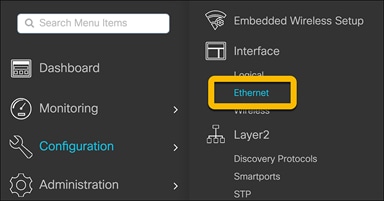
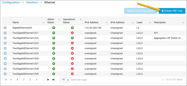
To create the VRFs, navigate to Configuration Ò Interface Ò Ethernet.
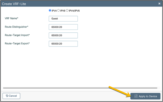
Click Create VRF-Lite.
In the Create VRF-Lite window, configure the corporate VRF with the requisite settings.
Click Apply to Device.
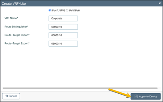
Repeat the steps to create the guest VRF.
If route leaking between VRFs and the Global Routing Table (GRT) is required, this can be done on the EWC without a next-hop. Please see the “BGP Support for IP Prefix Import” or “Policy Based Routing (PBR)” sections here: https://www.cisco.com/c/en/us/support/docs/ip/ip-routing/200158-Configure-Route-Leaking-between-Global-a.html
Create corporate and guest DHCP pools
The corporate and guest Dynamic Host Configuration Protocol (DHCP) pools can be located anywhere in the network, but for the purposes of this guide, the DHCP pools will be located on a 9300 Series switch.
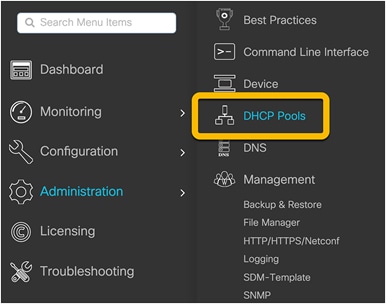
Navigate to Administration Ò DHCP Pools.
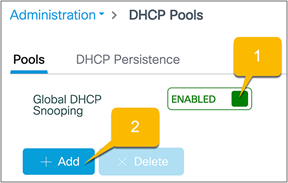
Ensure that Global DHCP Snooping is Enabled and click Add to create the corporate DHCP pool.
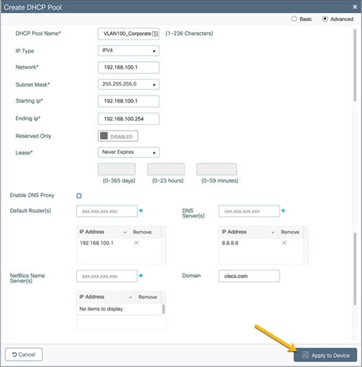
Configure the corporate DHCP pool with the required settings for the corporate network and click Apply to Device. Repeat these steps to create the guest DHCP pool.
If either or both of the corporate and guest networks are put into VRFs other than the default VRF, ensure that the DHCP server as well as other shared services, such as DNS, are reachable from the VRF. In the case where the DHCP server is located on the EWC switch, the DHCP pool for the required VLAN will need to be associated with the VRF. Additionally, DHCP snooping for the required VLAN will need to be configured (see the note below).
● Note: In Release 17.3, the DHCP pool and VRF association is done via CLI. Below is an example of the DHCP configuration for the corporate network on VLAN 100 in the corporate VRF.
configure terminal
ip dhcp snooping vlan 100
ip dhcp pool Corporate_100
vrf Corporate
Route leaking will need to be configured in order for the DHCP server as well as other shared services, such as DNS, to be reached by the devices in the VRFs.
Configure 802.1X security
If the deployment requires 802.1X security, the EWC supports authentication done locally on the switch as well as through an external Authentication, Authorization, and Accounting (AAA) server.
Local EAP authentication
For deployments without an external AAA server, 802.1X security can be done locally on the switch by configuring local Extensible Authentication Protocol (EAP) authentication.
To configure this option on the EWC, please follow the guide here: https://www.cisco.com/c/en/us/support/docs/wireless/catalyst-9800-series-wireless-controllers/215026-local-eap-authentication-on-catalyst-980.html
Authentication with external AAA server
Using an external AAA server, such as Cisco Identity Services Engine (ISE), will allow for dynamic VLAN assignments as well as Access Control Lists (ACL) and QoS policies based on the user’s role. This is one of the few ways to allow for role segmentation, as the EWC on Catalyst switches does not support Scalable Group Tag (SGT) segmentation.
For instructions on how to configure ISE users and policies, see: https://www.cisco.com/c/en/us/support/docs/wireless/catalyst-9800-series-wireless-controllers/213919-configure-802-1x-authentication-on-catal.html
Create a guest access captive portal (optional)
Before guests can access the network, you can have them be redirected to a webpage where they can be authenticated. The authentication methods are:
● WebAuth: This is a basic web authentication. The controller presents a policy page with the username and password. You need to enter the correct credentials to access the network.
● Consent or web-passthrough: The controller presents a policy page with the Accept or Deny buttons. Users need to click the Accept button to access the network.
● Webconsent: This is a combination of the WebAuth and consent web authentication types. The controller presents a policy page with Accept or Deny buttons along with username or password. Users need to enter the correct credentials and click the Accept button to access the network.
Follow the steps in the link below to configure this option: https://www.cisco.com/c/en/us/td/docs/wireless/controller/9800/17-3/config-guide/b_wl_17_3_cg/m_vewlc_sec_webauth_cg.html
Create Access Control Lists (ACLs)
For more information on configuring ACLs, see the following link: https://www.cisco.com/c/en/us/td/docs/wireless/controller/9800/17-3/config-guide/b_wl_17_3_cg/m_conf_ipv4_acl_ewlc.html
For cases in which separate VRFs will not be configured for the different networks, ACLs can be configured to keep the networks from communicating.
Additionally, these can be used to prevent networks or devices within the same VRF from communicating.
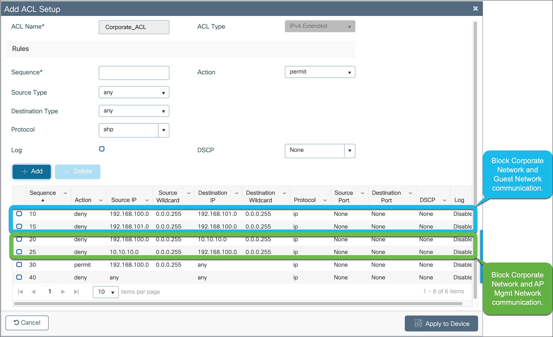
Below is an example of ACLs used to prevent the AP management, corporate, and guest networks from communicating when they are all within the same VRF.
ACL to prevent communication between the AP management, corporate, and guest networks
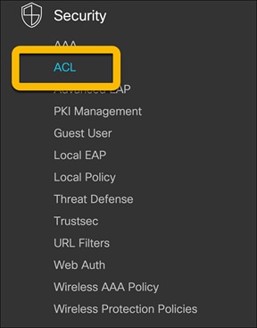
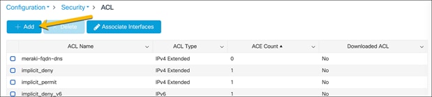
Navigate to Configuration Ò Security Ò ACL.
On the ACL page, click Add.
Configure the corporate ACL to meet the requirements of the network. Click Apply to Device when done.
An example of a corporate ACL is shown below.
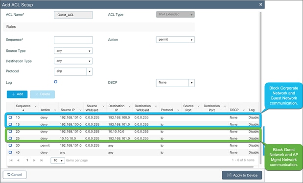
Repeat the steps to configure the guest ACL to meet the requirements of the network.
Click Apply to Device when done.
An example of a guest ACL is shown below.
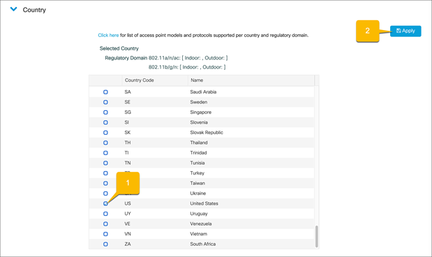
Set country codes for APs
To ensure that each radio’s broadcast frequency bands, interfaces, channels, and transmit power levels are compliant with country-specific regulations, the country that the EWC will be used in must be set.
● Note: For Release 17.3, set the country code through the Command-Line Interface (CLI) with the following commands:
configure terminal
wireless country <Country-Code>
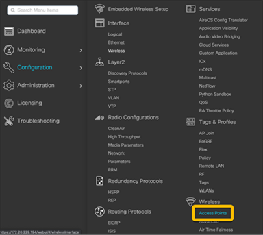
Navigate to Configuration Ò Wireless Ò Access Points.
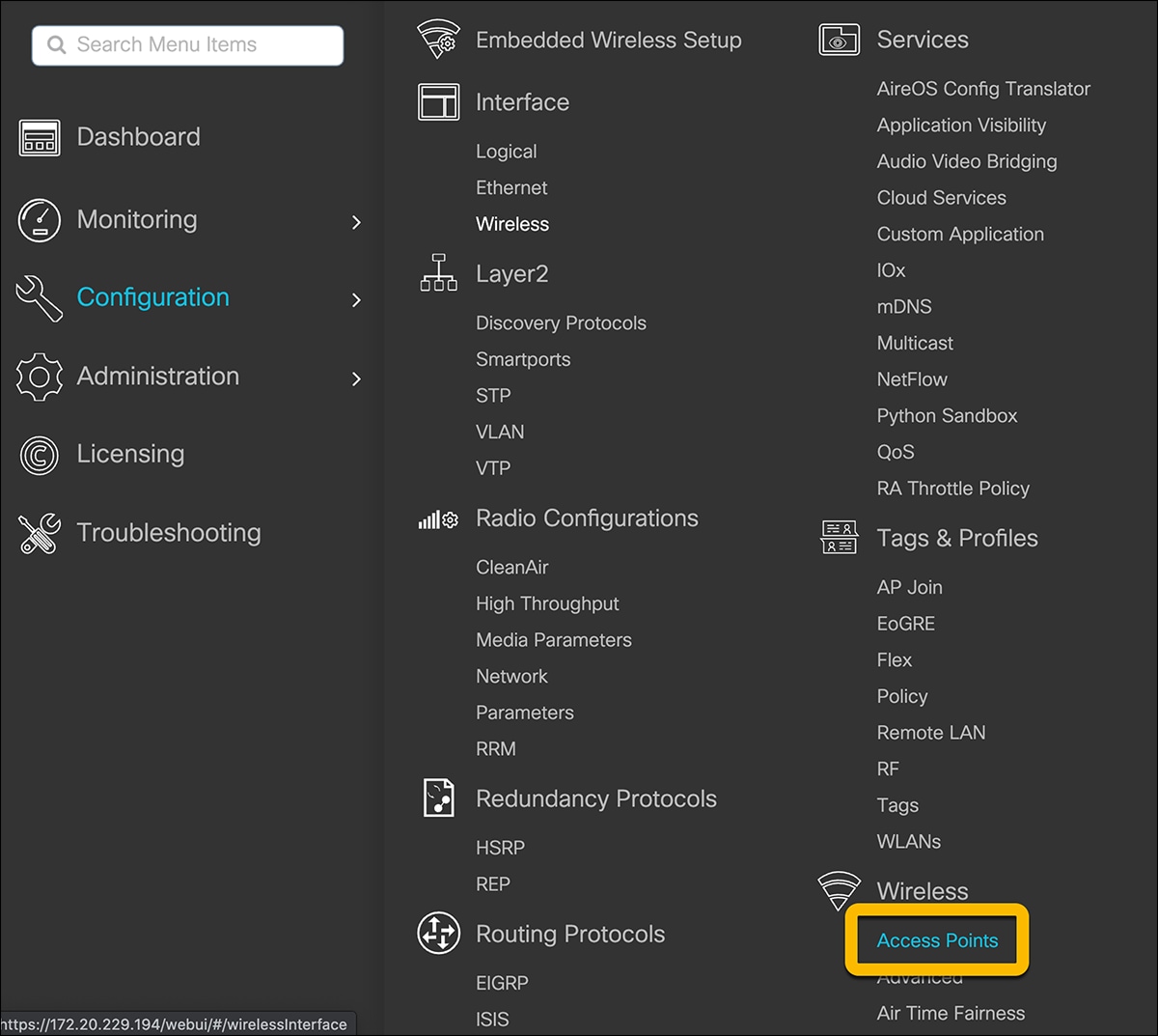
In the Country section, select the applicable country from the table and click Apply. This ensures that the APs that join the EWC will be in compliance with the selected country.
Enable the embedded wireless setup
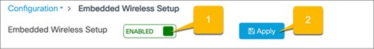
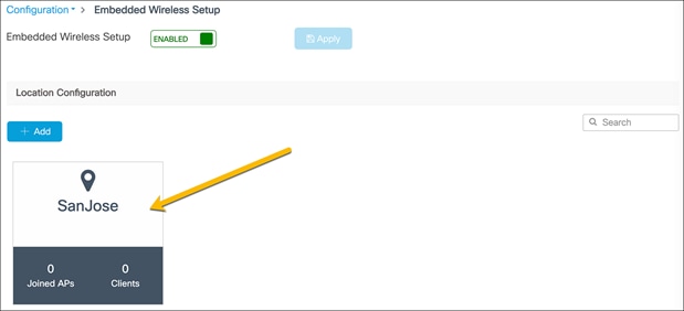
The EWC supports only the location-based workflow to configure the wireless networks. This is similar to the Basic Setup workflow on the Catalyst 9800 appliances. To access the workflow, navigate to the EWC configuration page by going to Configuration Ò Embedded Wireless Setup or clicking the wireless icon in the dashboard.

If the loopback address is configured, there will be a toggle for enabling and disabling the EWC. Set the toggle to Enabled and click Apply.
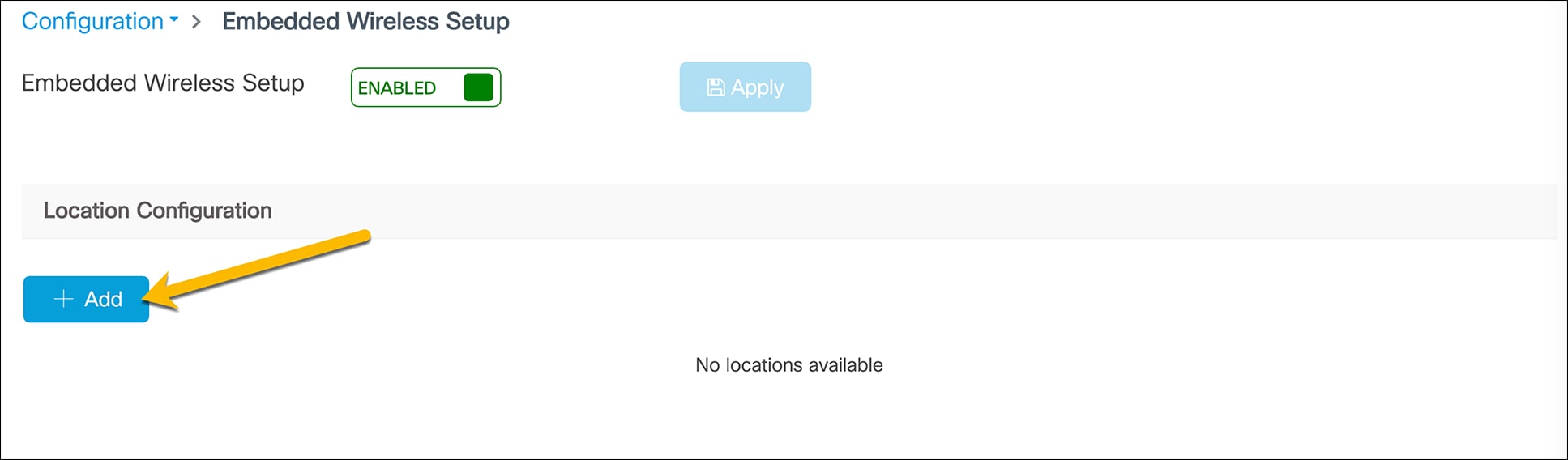
Click the Add button to create a new location.
● Note: The EWC supports only a single location. When clicking the Add button after a location has been configured, the WebUI will redirect to the settings page for the existing location.
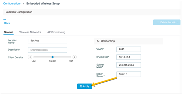
Enter the Location Name, Client Density, and AP Onboarding details. Click Apply.
● Note: The AP Onboarding VLAN ID is required to be between 2045 and 4094 to be consistent with the INFRA VLAN requirements. The VLAN chosen for the APs should be different than the VLANs used for clients.
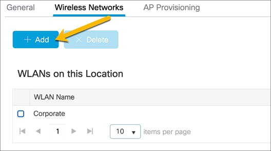
Create a corporate wireless network
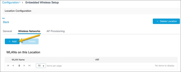
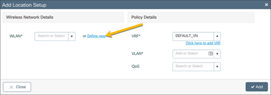
Go to the Wireless Networks tab and click Add.
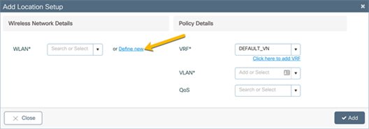
In the Add Location Setup window, click Define new to create the corporate WLAN.
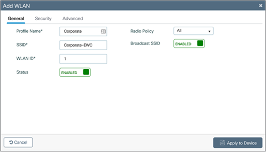
Corporate WLAN configuration
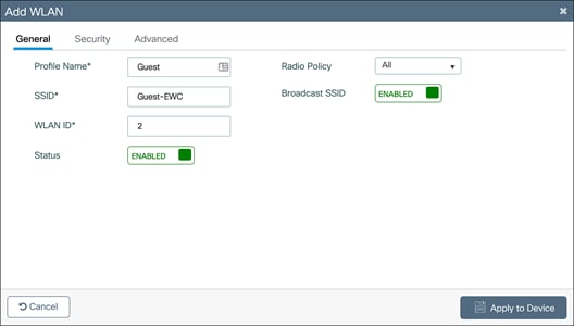
General tab configuration
In the Add WLAN window, set the Profile Name, SSID, and WLAN ID as well as toggling the Status to Enabled.
WLAN security configuration
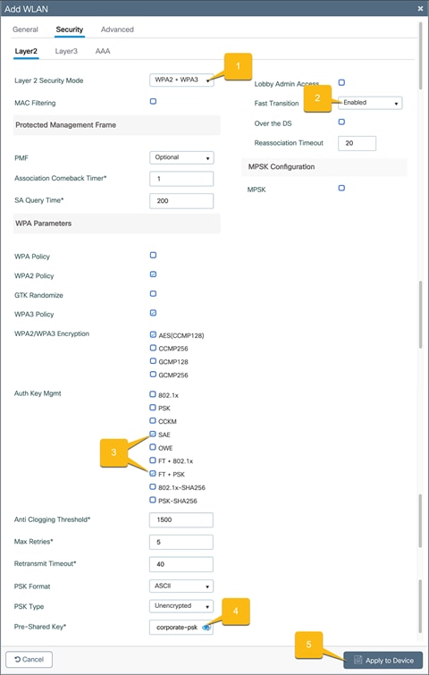
Pre-shared key
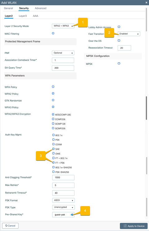
Go to the Security Ò Layer2 tab and configure the Layer 2 security.
1. Set the Layer 2 Security Mode to WPA2 + WPA3.
2. Set Fast Transition to Enabled.
3. Set the Auth Key Management to SAE and FT + PSK.
4. Set the corporate WLAN password.
5. Click Apply to Device.
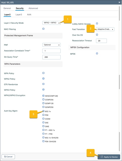
802.1X security
Go to the Security Ò Layer2 tab and configure the Layer 2 security.
1. Set the Layer 2 Security Mode to WPA2 + WPA3.
2. Set Fast Transition to Adaptive Enabled.
3. Set the Auth Key Management to 802.1x.
4. Click Apply to Device.
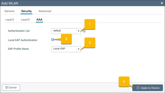
Local EAP authentication
Go to the Security Ò AAA tab.
1. Set the Authentication List to the configured local AAA authentication method.
2. Check Local EAP Authentication.
3. Select the configured EAP Profile Name.
4. Click Apply to Device.
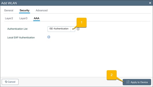
Authentication with an external AAA server
Go to the Security Ò AAA tab.
1. Set the Authentication List to the ISE AAA authentication method that was configured in the “Configure 802.1X security – Authentication with external AAA server” section.
2. Click Apply to Device.
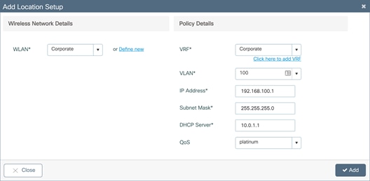
Corporate wireless policy details
In the Add Location window, set the required VRF, VLAN, and QoS details. Click Add.
· Note: The VLAN for the corporate clients should be different than the VLAN for AP onboarding. Also, ensure that the corporate VLAN has IP connectivity from the EWC to the rest of the network. If the corporate network is placed in a VRF other than the default VRF, the Switch Virtual Interface (SVI) for the corporate VLAN will need to be manually added to the corporate VRF.
Enter a VLAN that does not exist on the switch and does not have an SVI configured. If the corporate VLAN and SVI have not yet been configured, the details can be added in this window. Otherwise, if both the VLAN and SVI are configured, select the VLAN from the drop-down menu.
● Note: The switch comes preconfigured with four different QoS policies that will prioritize different traffic types.
◦ Platinum: Used for VoIP clients
◦ Gold: Used for video clients
◦ Silver: Used for traffic that can be considered best effort
◦ Bronze: Used for Non-Real-Time (NRT) traffic
To create custom QoS and AVC polices, please see: https://www.cisco.com/c/en/us/td/docs/wireless/controller/9800/17-3/config-guide/b_wl_17_3_cg/m_wireless_qos_cg_vewlc.html
Create a guest wireless network
The EWC on Catalyst switches does not support being used as a guest anchor nor as a guest foreign controller. All guest network configurations will be done on the EWC on the switch.
While still in the Wireless Networks tab, create the guest WLAN by clicking Add.
In the Add Location Setup window, click Define new to create the guest WLAN.
Guest WLAN configuration
General tab configuration
In the Add WLAN window, set the Profile Name, SSID, and WLAN ID as well as toggling the Status to Enabled.
WLAN security configuration
Pre-shared key
Go to the Security Ò Layer2 tab and configure the Layer 2 security.
1. Set the Layer 2 Security Mode to WPA2 + WPA3.
2. Set Fast Transition to Enabled.
3. Set the Auth Key Management to SAE and FT + PSK.
4. Set the Guest WLAN password.
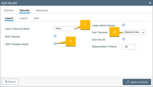
WebAuth captive portal
Go to the Security Ò Layer2 tab.
1. Set the Layer 2 Security Mode to None.
2. Set Fast Transition to Adaptive Enabled.
3. Uncheck OWE Transition Mode.
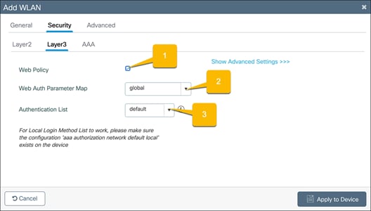
Go to the Security Ò Layer3 tab.
1. Check the Web Policy option.
2. Choose the Web Auth Parameter Map that was configured.
3. If you will be having users log in using the captive portal, select the configured, local Authentication List.
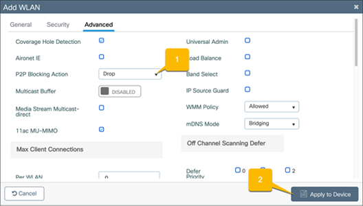
Prevent guest hosts from communicating with each other
Go to the Advanced tab.
1. Set P2P Blocking Action to Drop.
2. Click Apply to Device.
Guest wireless policy details
In the Add Location window, set the required VRF, VLAN, and QoS details. Click Add.
● Note: The VLAN for the guest clients should be different than the VLAN for AP onboarding. Also, ensure that the guest VLAN has IP connectivity from the EWC to the rest of the network. If the guest network is placed in a VRF other than the default VRF, the SVI for the guest VLAN will need to be manually added to the guest VRF.
Enter a VLAN that does not exist on the switch and does not have an SVI configured. If the guest VLAN and SVI have not yet been configured, the details can be added in this window. Otherwise, if both the VLAN and SVI are configured, select the VLAN from the drop-down menu.

Apply ACLs to WLANs
For cases in which networks for WLANs are in the same VRF and are not allowed to communicate, apply the created ACLs to the respective WLANs.
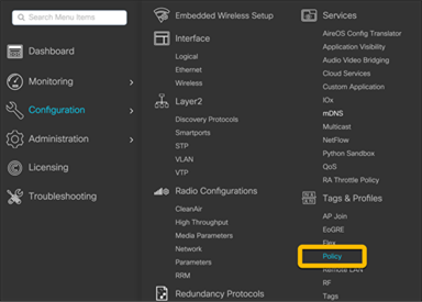
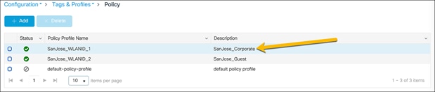
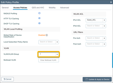
Navigate to Configuration Ò Tags and Profiles Ò Policy.
Select the policy name that matches the WLAN that requires an ACL.
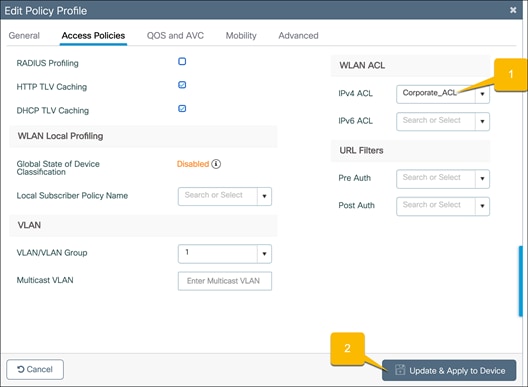
Go to the Access Policies tab in the Edit Profiles window.
1. Set the IPv4 ACL to the ACL for the network.
2. Click Update and Apply to Device.
Repeat the steps for all the other required networks.
Onboard and provision wireless access points
Setting up network topology
In order for the access points to discover and join the EWC, they need to be assigned to the same VLAN that was configured for the AP onboarding. The AP onboarding VLAN should be in the GRT of the EWC even when multiple VRFs are configured. Additionally, if the DHCP server for the AP onboarding is located on a device other than the EWC, ensure that it is reachable by the access points during the DHCP request.
If the APs are directly connected to the EWC switch, the switch ports where the APs are connected can be assigned to correct VLAN.
Otherwise, if there are intermediate switches between the EWC and the access points, the connections between the EWC switch and intermediate switches need to be Layer 2 connections with the appropriate VLAN trunking configured. Since the APs are required to be on the AP onboarding VLAN, the VLAN ID for all traffic sent between the AP and EWC needs to be preserved. If there are any Layer 3 hops between the AP and EWC, the AP onboarding VLAN ID of the traffic is lost, preventing the AP from joining the APs.
Tagging the access points
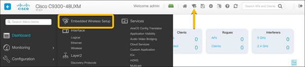
Navigate to the EWC configuration page by going to Configuration Ò Embedded Wireless Setup or clicking the wireless icon in the dashboard.
Select the created site.
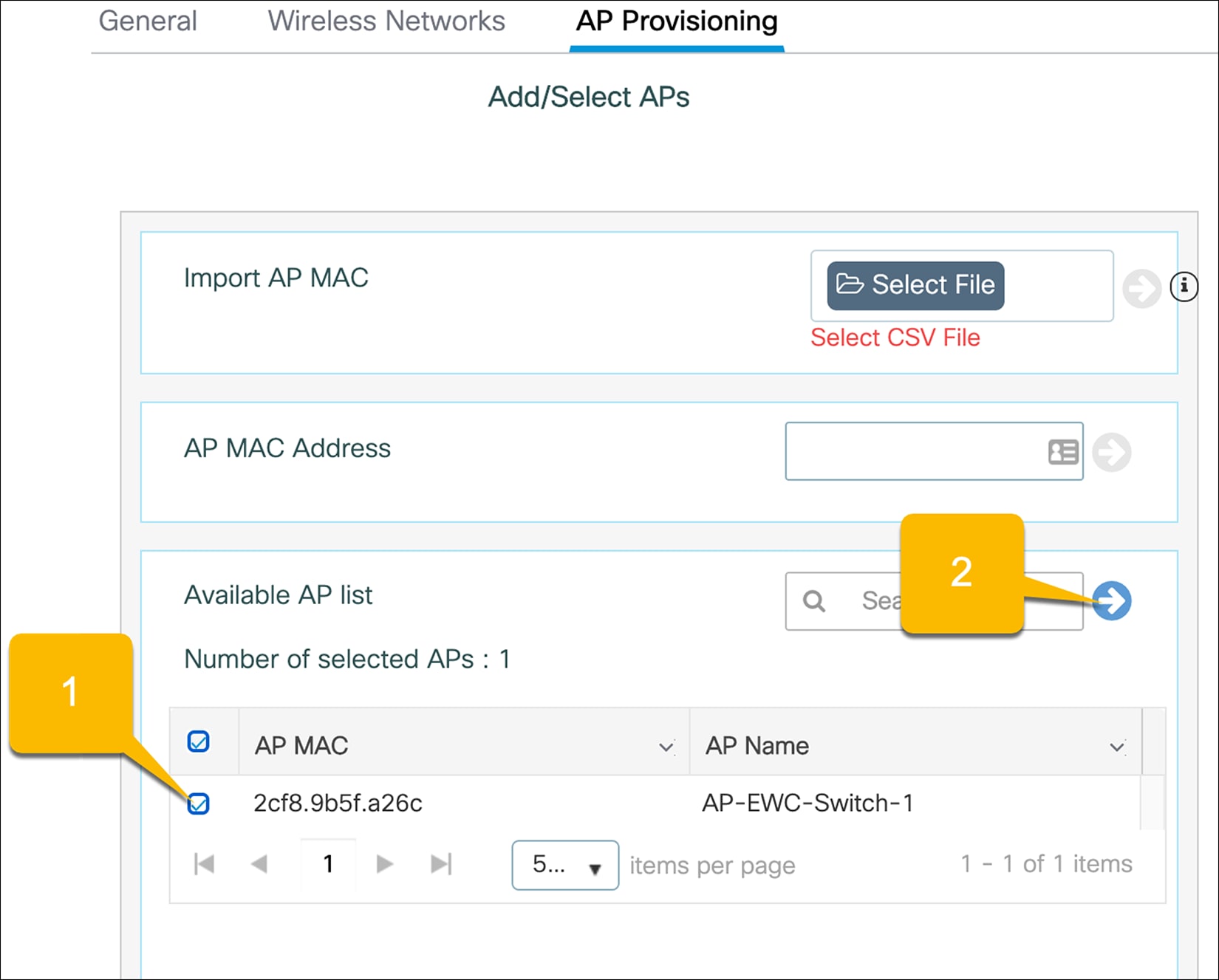
Go to the AP Provisioning tab.
1. Select the APs from the list to add to the site.
● Note: If the access points are not appearing in the Available AP List, this means they have not successfully joined the EWC by creating the CAPWAP tunnels. Once the APs have successfully joined, they will appear in the Available AP List. If the APs do not automatically populate the list, refresh the page. If the APs have joined, they will now appear.
2. Click the blue arrow icon to add them to the associated AP list.
The AP status should say Joined, indicating the AP has formed the CAPWAP tunnel with the AP. To tag the AP and add it to the configured location, click Apply.
● Note: The APs that are added may need to have the correct software version installed and will be reloaded.
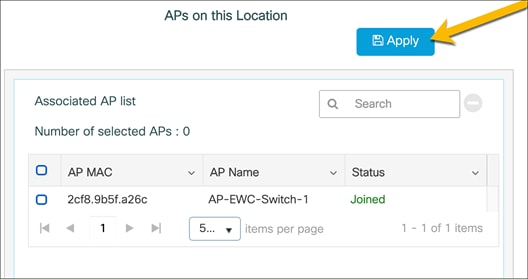
The APs will then be tagged with the necessary policy, site, and RF tags for the location. Through the location-based workflow, these are automatically created.
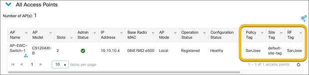
To verify that the APs have been successfully added, go to Configuration Ò Wireless Ò Access Points.
For the APs that were added, check that the tags match those of the site.
Other methods of adding APs
CSV file upload for AP tagging
If multiple APs need to be added to the site at one time, they can be added using a CSV file of all the APs’ MAC addresses. With this method, the AP does not need to be joined with the EWC to be tagged and added to the site. Upon joining the EWC, the AP will automatically be tagged.
Navigate to the EWC configuration page by going to Configuration Ò Embedded Wireless Setup or clicking the wireless icon in the dashboard.
Select the created site.
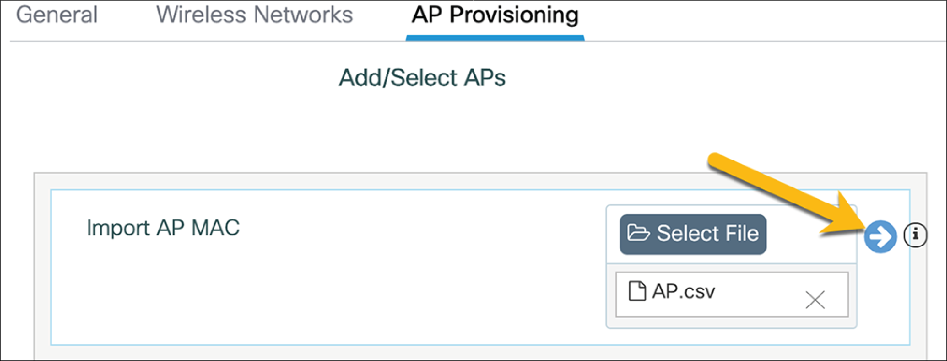
Go to the AP Provisioning tab.
Upload the CSV file and click the blue arrow to add the APs to the location.
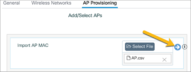
Click Apply to add the APs to the site.
● Note: The APs that are added may need to have the correct software version installed and will be reloaded.

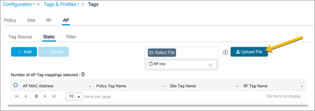
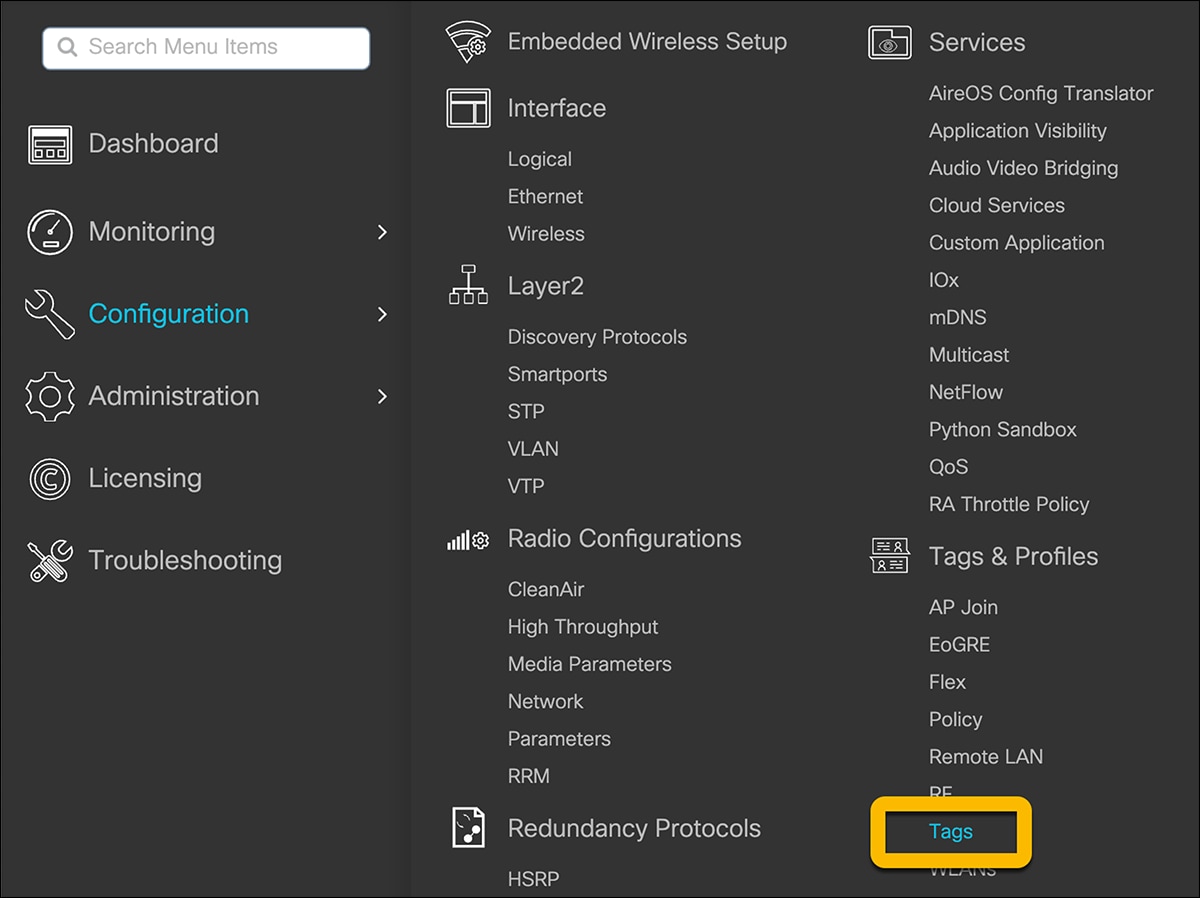
CSV files can also be uploaded by going to Configuration Ò Tags and Profiles Ò Tags. This will allow for multiple APs to be added to different locations.

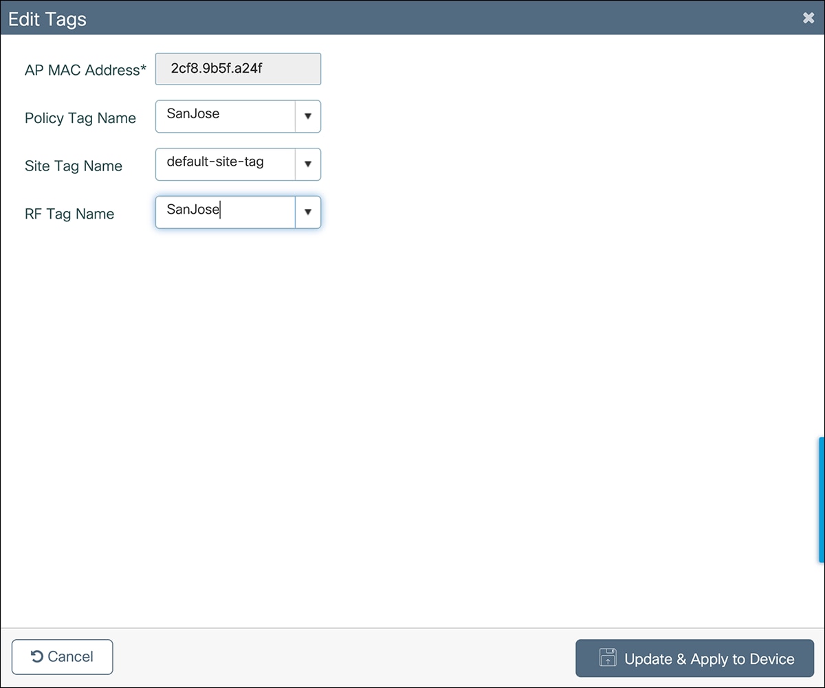
Go to the AP tab and the Static subtab. Upload a CSV file. The file can have the following columns: AP MAC address, Policy Tag name, Site Tag name, and RF Tag name. The only mandatory column is the AP MAC address. If the policy, site, and RF tags are included in the file, the APs will be automatically mapped with those tags, and once the APs join the EWC they will be correctly tagged. If they are not included, the AP will be mapped to the default policy, site, and RF tags.
The steps to change the AP tag mappings from the default tags to the required tags are shown below.
Select each of the APs and assign the required policy, site, and RF tags.
Regular expressions (regex) rules for AP tagging
APs can also be added to the site by using regex rules based on the AP name. Depending on the AP name, it will be tagged with the necessary tags upon joining the EWC. As with the CSV file upload method, the AP does not need to be joined with the EWC to tag and assign it to the location.
Navigate to Configuration Ò Tags and Profile Ò Tags.
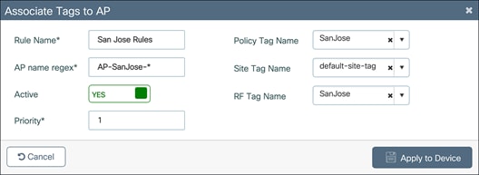
Go to the AP tab and the Filter subtab. Click Add.
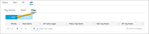
In the Associate Tags to AP window, fill out the requisite AP name regex* rules to match the AP name and associate the appropriate Policy, Site, and RF tags for the APs. Click Apply to Device.
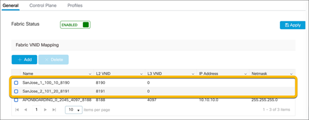
Note: WLAN VLANs
Due to the EWC being deployed in fabric mode and the data plane using VXLAN, when the VLAN is viewed in the WLAN policy, the VLAN group does not match what was previously configured.
To verify that the VLAN matches what was previously configured, go to Configuration Ò Wireless Ò Fabric.
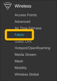
In the General tab, there is a list of the fabric VNID mappings. The naming convention is <location>_<WLAN_ID>_<VLAN>_<L3_VNID>_<L2_VNID>. The names below will show the correct VLAN associated with WLANs configured.
● Note: The Layer 3 VNID will match what was configured for the VRF.