Cisco Compute Security Hardening Guide for Standalone Systems White Paper
Available Languages
Bias-Free Language
The documentation set for this product strives to use bias-free language. For the purposes of this documentation set, bias-free is defined as language that does not imply discrimination based on age, disability, gender, racial identity, ethnic identity, sexual orientation, socioeconomic status, and intersectionality. Exceptions may be present in the documentation due to language that is hardcoded in the user interfaces of the product software, language used based on RFP documentation, or language that is used by a referenced third-party product. Learn more about how Cisco is using Inclusive Language.
| Prepared for |
Prepared by |
|
| V2.0 |
Cisco Field |
Aaron Kapacinskas |
| Changes |
||
| Added Appendix C - USB BIOS Install boot procedure |
||
| Added Appendix D - TPM and TAM details for secure boot |
||
| Added Appendix E - Microchip tri-mode disk controller details |
||
| Added information about TPM self-tests |
||
| Added additional information around expired secure boot certificates |
||
| Updated PQC |
||
| Added CIMC session management |
||
This document contains confidential material that is proprietary to Cisco Systems, Inc. The materials, ideas, and concepts contained herein are to be used exclusively to assist in the configuration of Cisco® hardware and software solutions.
The documentation set for this product strives to use bias-free language. For purposes of this documentation set, bias-free is defined as language that does not imply discrimination based on age, disability, gender, racial identity, ethnic identity, sexual orientation, socioeconomic status, and intersectionality. Exceptions may be present in the documentation due to language that is hardcoded in the user interfaces of the product software, language used based on standards documentation, or language that is used by a referenced third-party product.
We recommend reviewing the Cisco UCS® release notes, installation guide, and user guide before proceeding with any configuration. Please contact Cisco Support or your Cisco representative if you need assistance.
This guide focuses on implementing a Cisco Unified Computing System™ (Cisco UCS) with emphasis on best practices around security. The guide focuses on deploying Cisco UCS in standalone mode; that is, without Cisco Intersight® (either local or SaaS) and without Cisco UCS Manager (UCSM) (that is, there is no use of Fabric Interconnects [FIs]). This deployment scenario sees the compute system utilizing only the Cisco Integrated Management Console (CIMC) for management. This hardening guide will explore the Cisco UCS ecosystem, hardware capabilities, and software settings that are critical to a secure deployment. There is no discussion of policies or service profiles since those require either UCSM or a deployment using Intersight. In standalone mode, configuration is handled on a per-server basis utilizing the Cisco Integrated Management Console (CIMC), which is the built-in Baseboard Management Console (BMC) present on each Cisco UCS system.
At the core of the Cisco UCS platform lies a development philosophy centered on proactive security measures. With an approach designed for preemptive threat mitigation and continuous enhancement, Cisco leverages in-house technologies and research to fortify its UCS architecture against emerging threats. Incorporating robust industry practices and adhering to stringent security protocols, the Cisco UCS platform is built to meet the highest standards of security certifications, ensuring compliance with regulatory frameworks and assuring customers of a resilient and safeguarded infrastructure. Moreover, the management features embedded within the Cisco UCS solution provide administrators with comprehensive tools for monitoring, auditing, and controlling access, enabling proactive threat identification and rapid response to potential security breaches.
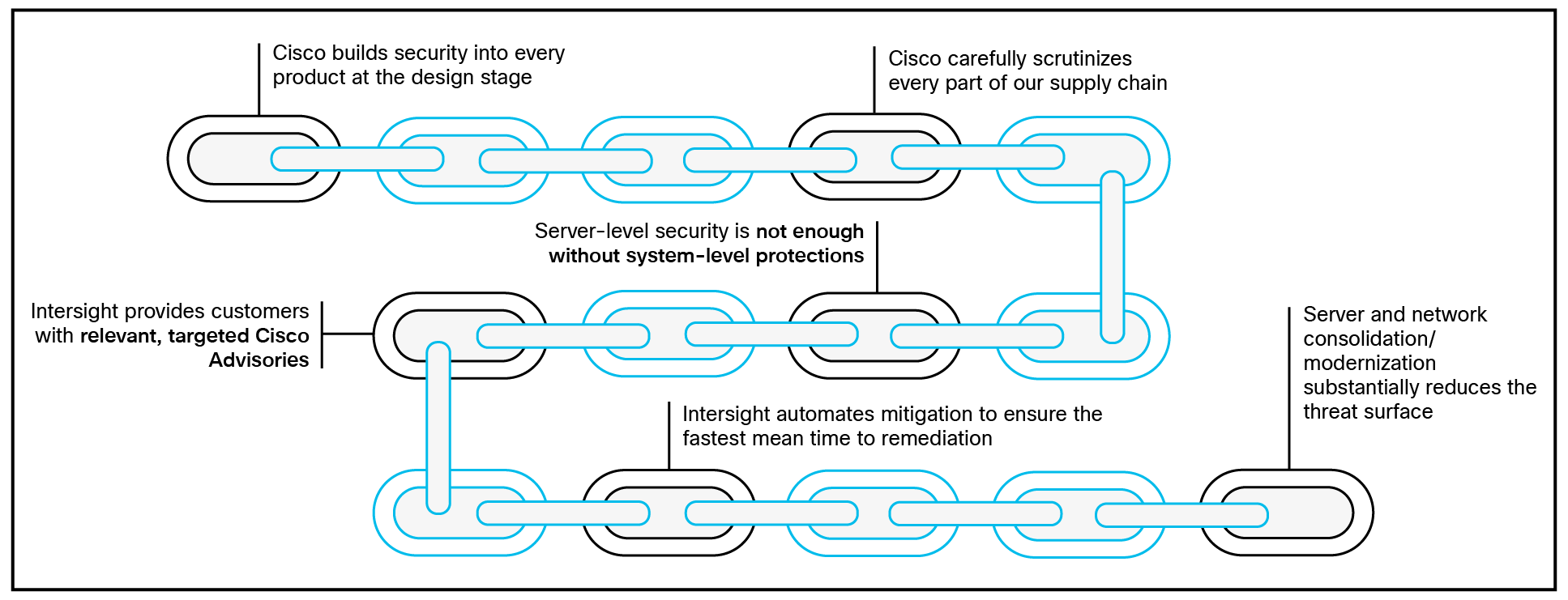
The Cisco security value chain
In addition to its development and certification framework, Cisco UCS utilizes advancements in confidential computing and secure storage to keep user applications and data protected. Implementing NIST-approved encryption techniques, secure boot processes, and hardware-based isolation mechanisms, UCS ensures data confidentiality, integrity, and availability throughout its lifecycle. Through secure storage solutions and federally certified secure interfaces, users leverage the UCS platform confidently, knowing that their data remains protected against unauthorized access. This white paper discusses the implementation of these features, demonstrating how Cisco UCS meets and exceeds the security and accountability requirements in today’s enterprise environments.
Cisco Unified Computing System solution components
A Cisco UCS compute system is available in many blade- or rack-mount configurations. Systems that come with Fabric Interconnects (FIs) can run with Cisco Unified Computing System Manager (UCSM or UCSM Managed Mode, UMM) or with Intersight cloud-management services (Intersight Managed Mode, IMM). Systems without Fis will run in standalone mode and can be managed through the baseboard management console (BMC also called the Cisco Integrated Management Console, CIMC) or with Intersight.
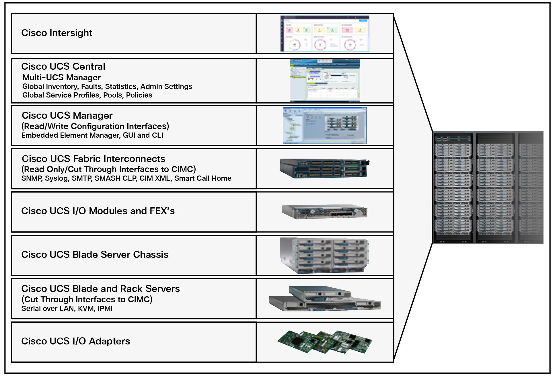
The Cisco UCS ecosystem with various server platforms and I/O adapters complemented with robust management and monitoring tools.
As shown in Figure 2, a typical Cisco UCS ecosystem comprises many fabric-related components, but in a standalone environment, these parts are not present. While a full deployment using an integrated fabric is the recommended method for a unified server architecture, this is not a hard requirement.
The rack-mount systems available as standalone systems are Cisco UCS M5/6/7/8 servers. Blade servers require a chassis that has an integrated fabric and so that it can operate in either UCSM mode (UMM) or Intersight-only mode (IMM).
Upstream or Top-of-Rack (ToR) switches are required to manage north-south traffic; that is, traffic to resources outside of the server itself. You should configure upstream switches to accommodate nonnative VLANs for Ethernet traffic.
Cisco UCS servers come in a variety of types, including rack servers and chassis-based blade (half- and full-size) servers. Some servers are specialized for specific applications (for example, AI), or for specific deployment types (for example, edge deployments). Such systems will have specific hardware designed to facilitate workloads, such as a bank of GPUs or a dedicated DPU-based smart NIC with an embedded firewall. For specific model details and the full line of available server form factors and capabilities, see the Cisco documentation for each server type. Regardless of the server type, the systems utilizing UMM will have the same or closely similar security considerations.
Cisco UCS ecosystem – Cisco Integrated Management Console (CIMC)
Cisco UCS C-Series rack-mount servers ship with CIMC firmware. CIMC is a separate management module built into the motherboard. A dedicated ARM-based processor, separate from the main server CPU, runs the Cisco IMC firmware. The system ships with a running version of the firmware. You can update the firmware, but no initial installation is needed.
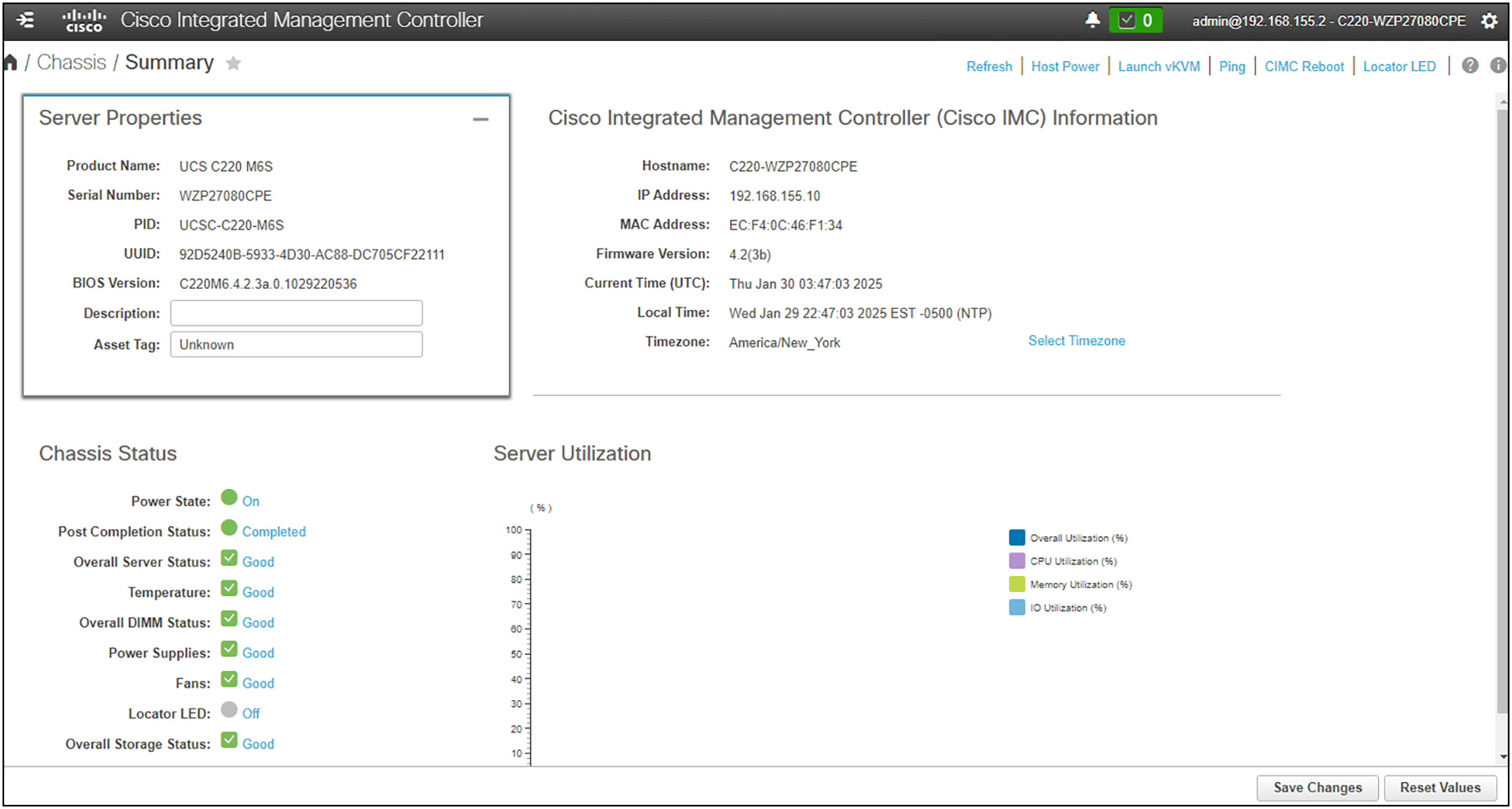
The summary screen in the CIMC UI. This is the first screen you see upon login.
Cisco UCS C-Series rack servers support operating systems such as Windows, Linux, VMware ESXi, Oracle, and so on. For more information on supported operating systems, see the Unified Computing Servers documentation. You can use the CIMC to install an OS on the server using the KVM console and vMedia.
The CIMC management service is used only when the server is operating in standalone mode. If your Cisco UCS C-Series server is integrated into a UCS system with fabric interconnects, you must manage it using Cisco UCS Manager, or you must use the Cisco Intersight SaaS service to claim and manage the system.
Sizing a Cisco UCS system, regardless of management mechanism (that is, UCSM, IMM, or standalone), is an important aspect of securing the system, because the nature of the deployment can determine or guide various secure system decisions. For example, if it makes sense to deploy your system using a virtualization solution, then employing Intel® TDX would be an important consideration for fencing the virtual environments when designing for confidential computing. Bare-metal or containerized deployments would have other considerations around use of Intel SGX or AMD SEV. There are also ramifications regarding storage at rest for applications you may be targeting or for air-gapped and non-networked environments.
Sizing Cisco UCS for applications involves determining the appropriate hardware resources and configurations to meet the performance and capacity requirements of the applications, whether they run on bare metal or in virtualized environments. Here are some guidelines on how Cisco UCS systems are sized for applications in both scenarios:
Sizing for bare-metal applications:
● Define application requirements:
◦ Identify specific resource requirements of the application, including CPU, memory, storage, and network bandwidth.
◦ Consider peak workloads, expected growth, and any specific performance characteristics of the application.
● Select the appropriate Cisco UCS server model:
◦ Choose a Cisco UCS server model that aligns with the performance and scalability requirements of the application.
◦ Consider factors such as the number of sockets and cores, memory capacity, available PCIe slots, and storage options.
◦ Choose a CPU that meets your preferred confidential computing needs.
● Configure CPU and memory:
◦ Determine the optimal CPU configuration based on the application's CPU utilization patterns.
◦ Allocate sufficient memory to meet the application's requirements, considering such factors as caching, data processing, and scalability.
● Storage configuration:
◦ Select the appropriate storage configuration, including the type of storage (for example, HDD, SSD) and RAID levels.
◦ Consider the required storage capacity, I/O performance, and redundancy needs.
◦ Determine if you need to use Data At Rest Encryption (DARE) and select SEDs if needed.
● Network considerations:
◦ Size the network infrastructure based on the application's network bandwidth requirements.
◦ Determine the number and type of network interfaces needed for the application.
● Power and cooling requirements:
◦ Assess the power and cooling requirements of the chosen Cisco UCS server to ensure they align with the data center's capabilities.
● Consider future growth:
◦ Plan for future growth by selecting a Cisco UCS server model that provides scalability to accommodate increased workloads over time.
Sizing for virtualized environments:
● Hypervisor selection:
◦ Choose a hypervisor (for example, VMware vSphere, Microsoft Hyper-V) based on the application's compatibility and feature requirements.
◦ Choose an appropriate CPU to meet your confidential computing needs specific to virtualized deployments.
● Calculate virtual resource requirements:
◦ Estimate the resource requirements for each Virtual Machine (VM), including vCPUs, memory, and storage.
◦ Consider factors such as resource overcommitment, VM density, and peak usage patterns.
● Determine host-to-VM ratio:
◦ Decide on the host-to-VM ratio based on the application's characteristics and the capabilities of the selected Cisco UCS server model.
◦ Consider such factors as CPU and memory oversubscription, workload variability, and HA (high availability) considerations.
● Consider network and storage virtualization:
◦ Plan for network virtualization (for example, VLANs, VXLANs) and storage virtualization (for example, SAN or NAS integration) to meet the needs of virtualized workloads.
In both scenarios, working closely with application owners, understanding the application's characteristics, and regularly monitoring and adjusting the infrastructure are critical for ensuring optimal performance and resource utilization. It is also at this time that you should consider how this system will fit into any key-management solutions you have for encrypted services and how you will implement any firewall or other perimeter access and authentication solutions. Cisco UCS Manager provides a centralized platform for managing and configuring servers, providing a unified approach to hardware management in both bare-metal and virtualized environments.
Component failure and redundancy
Cisco UCS is designed with a strong emphasis on hardware redundancy to enhance system reliability and availability. The hardware redundancy in Cisco UCS involves redundant components and mechanisms to handle failures effectively. In encrypted environments it is critical that access to the PKI infrastructure is maintained both for reliable access to systems and for any potential secure decommissioning that may need to occur.
Here are some key aspects of standalone Cisco UCS hardware redundancy and how failures are handled:
● Power supply redundancy:
◦ Cisco UCS rack servers come with redundant power supplies to ensure continuous power availability.
● Multiple NICs and teaming:
◦ To protect against networking failures
● Predictive failure:
◦ Predictive failure alerts are generated to notify administrators of components that are likely to fail soon, allowing for proactive replacement.
● Automated failure handling:
◦ Cisco UCS is designed to automatically handle failures without manual intervention.
◦ When a failure occurs, the system can automatically reroute traffic, shift workloads, or initiate other recovery measures to minimize downtime.
By integrating these redundancy features, Cisco UCS aims to deliver a highly reliable and available computing infrastructure. The emphasis on automated failure handling and proactive monitoring helps reduce the impact of hardware failures and ensures the continuous operation of critical workloads in data center environments.
The Cisco Secure Development Lifecycle
Cisco products and components are developed, integrated, and tested using the Cisco Secure Development Lifecycle (CSDL). Secure product development and deployment has several components, ranging from following specified design and development practices, to testing their implementation, to providing customers with a set of recommendations for deployments that maximize the security of their system.
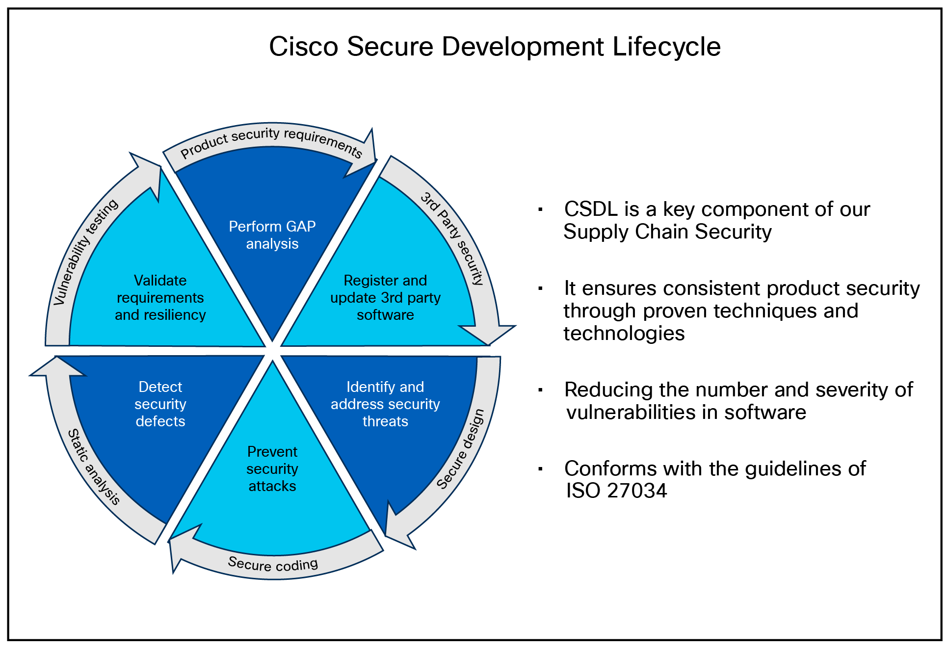
The Cisco Secure Product Development Lifecycle.
A poor product design can open the way to vulnerabilities. The CSDL is designed to mitigate these potential issues. At Cisco, our secure-design approach requires two types of considerations:
● Design with security in mind.
● Use threat modeling to validate the design's security.
● Designing with security in mind is an ongoing commitment to personal and professional improvement through:
◦ Training
◦ Applying Product Security Baseline (PSB) design principles
◦ Considering other industry-standard secure-design principles
◦ Being aware of common attack methods and designing safeguards against them
◦ Taking full advantage of designs and libraries that are known to be highly secure
◦ Protecting all potential entry points
● Cisco also reduces design-based vulnerabilities by considering known threats and attacks:
◦ Follow the flow of data through the system.
◦ Identify trust boundaries where data may be compromised.
◦ Based on the data flow diagram, generate a list of threats and mitigations from a database of known threats, tailored by product type.
● Prioritize and implement mitigations to the identified threats. The goal of this effort is to enforce a set of security processes and ensure a security mindset at every stage of development:
◦ Secure design
◦ Secure coding
◦ Secure analysis
◦ Vulnerability testing
◦ Secure deployments
Each iteration of the product’s development addresses needs for ongoing security fixes and general feature enhancements that include security components (new deployment models, changes in management, partner onboarding, etc.). At every stage of development, the product(s) undergo potential enhancements relative to findings and new features.
● The system is configured in the Quality-Assurance (QA) testing stage to accommodate the relevant findings identified above and run through a typical deployment test.
● The result is a validated set of best practices for security and is communicated through the CSDL process and exposed in the documentation.
CSDL product adherence methodologies
Cisco CSDL adheres to Cisco Product Development Methodology (PDM), ISO/IEC 27034, and ISO 9000 compliance requirements. The ISO/IEC 27034 standard provides an internationally recognized standard for application security. Details for ISO/IEC 27034 can be found here. The ISO 9000 family of quality management systems standards is designed to help organizations ensure that they meet the needs of customers and other stakeholders while meeting statutory and regulatory requirements related to a product or service. ISO 9000 details are here.
The CSDL process is not a one-time approach to product development. It is recursive, with vulnerability testing, penetration testing, and threat modelling added to the subsequent development of CSDL. This process follows ISO 9000 and ISO 27034 standards as part of an internationally recognized set of guidelines. The approaches involved often use a solution-wide methodology; for example, utilizing our continually updated CiscoSSL crypto module to guarantee that Cisco UCS (along with other elements in the Cisco offering) is always secure and meets FIPS certification requirements.
Cisco Security and Trust Organization
Cisco Security and Trust Organization (S&TO) has the core responsibility to implement CSDL. In the effort to accomplish this, S&TO encompasses various groups with core responsibilities around delivering a secure product or responding to security concerns as they arise.
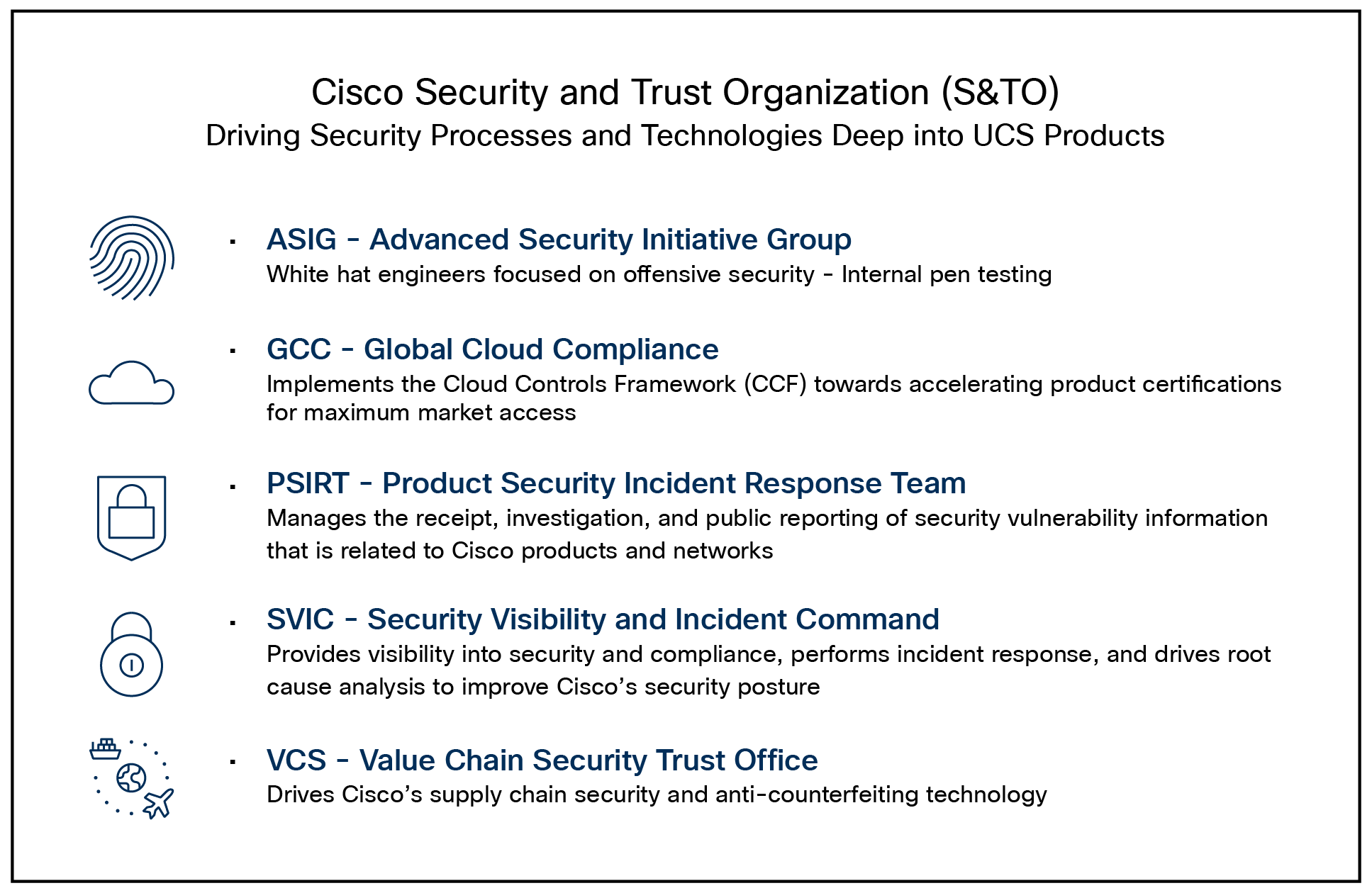
The various groups within Cisco S&TO
A critical aspect of secure product development and deployment is ensuring that the components that go into the system are legitimate and uncompromised. To this end, Cisco takes exceptional measures to ensure supply-chain integrity.
The Cisco Value Chain describes the development model used for all Cisco products, including Cisco HyperFlex®. Cisco is a leader in industry and international standards on counterfeit reduction and has been engaged in decades-long efforts to prevent and detect the distribution of counterfeit products. Cisco incorporates tools and processes to prevent counterfeiting—beginning with product development, through the manufacturing process, and in the marketplace.
In collaboration with Cisco’s Brand Protection, Legal, and other teams, an end-user portal has been developed to aid customers in these efforts and can be accessed at: anticounterfeit.cisco.com.
Cisco's Brand Protection has conducted numerous investigations into counterfeiting operations and worked with local law enforcement to disrupt those operations. The portal includes examples of the Brand Protection Team’s work over the years and the numerous resources that are available for Cisco customers and partners.
The Cisco Value Chain has the following characteristics:
● Comprehensive across all stages of a solution’s lifecycle
● Multilayer approach, with focused protection against:
◦ Source code corruption
◦ Hardware counterfeit
◦ Misuse of intellectual property
This multilayered approach is shown in Figure 6.
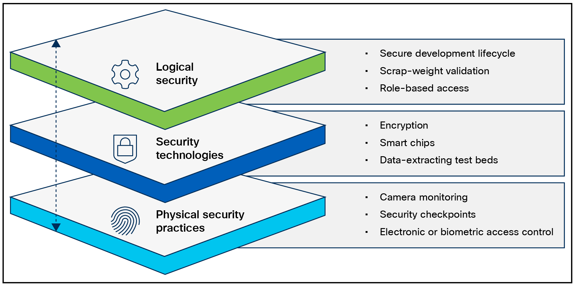
Layers of the Cisco Value Chain
Consortiums for secure vendors
Table 1. Secure vendor consortium memberships
| Name |
Component(s) |
Description |
Status |
| TAPA |
Supply chain |
The Transported Asset Protection Association's (TAPA) Security Standards act as a worldwide benchmark for supply-chain security and resilience, providing guidance, processes, and tools that protect assets and reduce loss exposure and the costs of cargo theft. |
Member |
| C-TPAT |
Supply chain |
Customs Trade Partnership Against Terrorism (CTPAT) Trade Compliance Program is a voluntary program that provides the opportunity for importers who have made a commitment of resources to assume responsibility for monitoring their own compliance in exchange for benefits. |
Member |
Advisories, vulnerabilities, and incident responses
Computer Emergency Response Team (CERT) advisories come up as new vulnerabilities are identified. Cisco’s internal CERT team monitors and alerts product groups to potential issues that might affect their respective components. When these items are identified by CERT or are otherwise indicated by vendor partners (VMware, etc.), patches are either developed or acquired from the respective vendors.
The Cisco Product Security Incident Response Team (PSIRT) is responsible for responding to Cisco product security incidents. The Cisco PSIRT is a dedicated, global team that manages the receipt, investigation, and public reporting of information about security vulnerabilities and issues related to Cisco products and services. Cisco defines a security vulnerability as a weakness in the computational logic (for example, code) found in software and hardware components that, when exploited, results in a negative impact to confidentiality, integrity, or availability. Cisco reserves the right to deviate from this definition based on specific circumstances. The Cisco PSIRT adheres to ISO/IEC 29147:2018, which are guidelines for disclosure of potential vulnerabilities established by the International Organization for Standardization.
The on-call Cisco PSIRT works 24 hours a day with Cisco customers, independent security researchers, consultants, industry organizations, and other vendors to identify possible security vulnerabilities and issues with Cisco products and networks.
All vulnerabilities disclosed in Cisco Security Advisories are assigned a Common Vulnerability and Exposures (CVE) identifier and a CVSS score to aid in identification. Additionally, all vulnerabilities are classified based on a Security Impact Rating (SIR).
Cisco uses version 3.1 of the Common Vulnerability Scoring System (CVSS) as part of its standard process of evaluating reported potential vulnerabilities in Cisco products. The CVSS model uses three distinct measurements or scores that include Base, Temporal, and Environmental calculations. Cisco provides an evaluation of the Base vulnerability score and, in some instances, a Temporal vulnerability score. End users are encouraged to compute the Environmental score based on their network parameters.
In addition, Cisco uses the Security Impact Rating (SIR) as a way to categorize vulnerability severity in a simpler manner. The SIR is based on the CVSS Base score, adjusted by PSIRT to account for variables that are specific to Cisco solutions , and is included in every Cisco Security Advisory.
Cisco PSIRT assigns a Common Vulnerabilities and Exposures Identifier (CVE ID) to any vulnerability that is found in a Cisco product and that qualifies to receive this identifier. Usually, all vulnerabilities with medium, high, or severe SIRs — that is, a CVSS score of 4.0 or greater — will qualify for a CVE-ID.
CVE and vulnerability remediation
CVE reporting is a function of the previously mentioned PSIRT alert mechanism and is the first step in vulnerability remediation. Once a CVE is known to affect a system, the patched release should be identified, downloaded and applied.
Additional vulnerability testing measures
Cisco also utilizes an internal tool for threat modeling called ThreatBuilder. This tool is used to explicitly map out application components and services and to identify potential attack surfaces and develop line items for direct evaluation. This information, along with that from industry tools, is used for vulnerability and exploit testing by Cisco’s ASIG (Advanced Security Initiatives Group). ASIG also uses fuzzing and manual testing as part of their suite of tools.
Cisco Technical Assistance Center
Cisco Technical Services helps to ensure that your Cisco products and network operate efficiently and benefit from the most up-to-date system and application software. When you need technical assistance, you can resolve issues quickly using the resources and tools available through your Cisco Technical Services contract.
To make sure your request is prioritized correctly, Cisco has established service request severity definitions. When you contact the Cisco Technical Assistance Center (Cisco TAC), you will be asked to assign your request a severity level.
● Severity 1 (S1): critical impact on the customer's business operations. Cisco's hardware, software, or as-a-service product is down.
● Severity 2 (S2): substantial impact on the customer's business operations. Cisco hardware, software, or as-a-service product is degraded.
● Severity 3 (S3): minimal impact on the customer's business operations. Cisco hardware, software, or as-a-service product is partially degraded.
● Severity 4 (S4): no impact on the customer's business operations. The customer requests information about features, implementation, or configuration for Cisco's hardware, software, or as-a-service product.
Open a service request to talk to a Cisco TAC engineer or use Cisco.com online resources to get technical information on demand.
Submit a Cisco service request
S1 or S2 service requests: for S1 or S2 issues, or if you do not have internet access for S3 and S4 issues, contact the Cisco TAC by telephone to submit your service requests.
S3 or S4 service requests: use Support Case Manager to quickly submit S3 and S4 service requests.
Three ways to get support
● Online: Support Case Manager
● Phone support: for a list of global contact numbers, see Cisco Worldwide Support Contacts.
Creating a service request using Support Case Manager
The fastest way to create S3 and S4 service requests and submit them to Cisco TAC is to use Support Case Manager.
What you will need:
● Your Cisco Service contract number
● Product serial number, chassis serial number, or virtual license number
● Product model number and its hardware configuration
● Physical location of the product
● Severity level of the issue (see definitions above)
The following information will help expedite your case:
● Meaningful case title stating the problem accurately
● History of the problem
● Network topology and explanation
● Output from a “show tech” command (if applicable) and all other relevant output
● Software versions and types of equipment
● Relevant syslog/tacac logs before the issue occurred
Escalation
If you are not satisfied with the progress on resolving your service request, you can escalate the case using the following options:
● Cisco Support Assistant at https://supportassistant.cisco.com/escalate. You will need to enter the case number and provide an escalation reason. A TAC manager will review your request and contact you.
● Contact your regional technical support center and ask to speak with a duty manager.
Status of Cisco service requests
You can use:
● Cisco Support Assistant to get case, bug, and RMA status, connect with the case owner, escalate or close the case. You can also use it to subscribe to case summary, status, and severity updates and get proactive alerts such as trending topics.
● Support Case Manager to view and update your support case. This is one of Cisco’s preferred secure options to upload information to the case. Learn more about the security and size limitations of file upload options here.
Service order/RMA status tool for advanced hardware replacement
During a Cisco TAC service request, if it is necessary to replace a hardware component, Cisco TAC will arrange for the correct component to be shipped to you from a service depot.
To track the status of your replacement part, enter your service order/RMA number, purchase order number, TAC service request number, TAC task, or “ship-to” ID, and the status tool will provide an update on your service order/RMA.
Cisco.com login user ID issues
Send an email to ic-support@cisco.com.
Figure 7 shows where to generate Tech Support data for upload to Cisco TAC during diagnostics and troubleshooting.
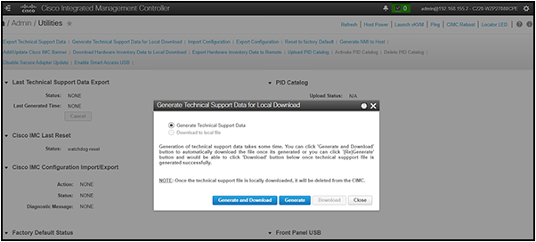
Generating Tech Support data for upload to Cisco TAC
Federal compliance and audit-based certifications are a critical component of a standardized and predictable security posture. They are critical in most federal deployments, especially those dealing with financial and defense arenas. The Cisco Global Certification Team (GCT) works to complete various certifications.
Common Criteria for Information Technology Security Evaluation
Common Criteria for Information Technology Security Evaluation (Common Criteria or CC) is an international standard (ISO/IEC 15408) for computer security certification, currently in v3.1 rev 5.
A key part of an evaluation assurance level (EAL) is the security target document. This comprises a rigorous definition of functions, features, and intended use, tailored for the specific hardware or software component under test (the target of evaluation [TOE]). The EAL rating determines the extent of the testing and the confidence that the security is as claimed. Simply, EAL indicates the degree to which something does what it says.
Cisco’s Unified Computing System (Cisco UCS) has achieved Common Criteria (CC) certification, which is a globally recognized standard for evaluating the security of IT products. This certification ensures that Cisco UCS meets stringent security requirements, making it a reliable choice for organizations with high security needs. Cisco UCS products, such as Cisco UCS Manager and various server models, have undergone rigorous evaluation to achieve this certification. This includes assessments of their secure installation, configuration, and operational use.
#20-0038305 EAL2 non-NDPP
CIMC 4.0 EAL2
UCS C-Series, UCS S-Series
#19-228723 EAL2 non-NDPP
UCSM 4.0
UCS B-Series, UCS C-Series, UCS S-Series, 2200, 2300, 2400, 6300
The Federal Information Processing Standard (FIPS) Publication 140-2 and 140-3 is a U.S. government computer-security standard used to approve cryptographic modules.
Cisco UCS is compliant with FIPS140-2 level 1 through direct implementation of the FIPS-compliant CiscoSSL crypto module. The module, once implemented, is vetted by a third-party that is federally certified to ascertain compliance status. Cisco UCS is compliant with FIPS 140-3 level 1 for new releases of UCSM and CIMC firmware moving forward, beginning in Fall of 2024, with systems using CiscoSSL and CiscoSSH with the FIPS Object Model (FOM) v7.3a or later.
● Utilizes CiscoSSL module
◦ Already FIPS-compliant
◦ SSH-approved cipher list
◦ SSL/TLS implementation
◦ Weak or compromised components eliminated
● Regularly updated
● Lab validates that the module is incorporated correctly.
◦ Builds logs
◦ Source access identifies calls to the module
◦ All admin access points to the cluster are covered here.
● SSH for CLI
● HTTPS for UI
A comprehensive list of Cisco FIPS-compliant products is listed here along with the corresponding reference with NIST:
● Cisco FIPS-Certified Products: http://www.cisco.com/c/en/us/solutions/industries/government/global-government-certifications/fips-140.html
● Cryptographic Module Validation Program (CMVP) vendor list:
◦ http://csrc.nist.gov/groups/STM/cmvp/documents/140-1/1401vend.html
◦ https://csrc.nist.gov/projects/cryptographic-module-validation-program/certificate/4747

Searching for FIPS vendor listings at the CVMP web site.
CNSA (Commercial National Security Algorithm)
This is a schema that is detailed in RFC 9151: RFC 9151: Commercial National Security Algorithm (CNSA) Suite Profile for TLS and DTLS 1.2 and 1.3 (rfc-editor.org).
The Commercial National Security Algorithm (CNSA) describes which algorithms should be in use and what their profiles should look like. It is intended to give guidance for secure and interoperable communications, including guidelines for certificates, for national security reasons.
Cisco supports both Elliptic Cryptographic Certificates (ECC) and RSA certificates, so these requirements are met:
● Elliptic Curve Digital Signature Algorithm (ECDSA) and Elliptic Curve Diffie-Hellman (ECDH) key pairs are on the curve P-384. FIPS 186-4, Appendix B.4, provides useful guidance for elliptic curve key pair generation that should be followed by systems that conform to RFC 9151.
● RSA key pairs (public or private) are identified by the modulus size expressed in bits; RSA-3072 and RSA-4096 are computed using moduli of 3072 bits and 4096 bits, respectively. Cisco’s FIPS certification through CiscoSSL implements federally approved crypto modules to satisfy the complexity requirements as well.
CNSA compliance is just a matter of making sure to implement a cryptographic ecosystem according to the CNSA requirements since Cisco UCS supports all the documented methods.
Other certifications and procedural guidelines
ISO/IEC 27001 is not a certification for specific pieces of hardware as much as it is a dozen or so “best practices” in the form of checklists and guidelines for how organizations manage their security controls internally. It observes such things as building access, password management, badging into a copier to make copies, etc. Training on a frequent basis is a part of the standard.
Cisco is ISO/IEC 27001-certified. This is a link to our ISO/IEC 27001 certificate: Cisco Secure Cloud Analytics (StealthWatch®) ISO/IEC 27001:2013, 27017:2015, 27018:2019.
The Office of Management and Budget (OMB) has directed [OMB-2020, OMB-2010, OMB-2005] the National Institute of Standards and Technology (NIST) to develop the technical infrastructure (standards and testing) necessary to support wide-scale adoption of IPv6 in the U.S. government (USG). In response, NIST developed a technical standards profile for U.S. government acquisition of IPv6-enabled networked information technology. The USGv6 Profile includes a forward-looking set of protocol specifications published by the Internet Engineering Task Force (IETF), encompassing basic IPv6 functionality and specific requirements and key optional capabilities for routing, security, multicast, network management, and quality of service.
The profile also contains NIST-defined requirements for IPv6-aware firewalls and intrusion-detection systems. The program also established a robust testing infrastructure to enable IPv6 products to be tested for compliance with profile requirements and for interoperability by accredited laboratories using standardized test methods. Cisco UCS platforms are in the process of completing this qualification.
The Defense Information Security Agency Approved Product List is a multifaceted U.S. federal certification that gives approval for products to operate in secure environments. It is currently under way with the Cisco Global Certification Team and the Cisco Compute Business Unit.
Other certifications and procedural guidelines
ISO 27001 is not a certification for specific pieces of hardware as much it is as a dozen or so “best practices” in the form of checklists and guidelines for how organizations manage their security controls internally. It observes such things as building access, password management, badging into a copier to make copies, etc. Training on a frequent basis is a part of the standard.
Cisco is ISO 27001-certified. This is a link to our ISO 27001 certificate: https://www.cisco.com/c/en/us/about/approach-quality/iso-27001.html.
ISO 27001:2013 - The Cisco Intersight platform has completed its ISO 27001:2013 First Surveillance Audit from the external certification body/auditor Coalfire, and the certificate issued has been uploaded to Trust Portal site. The First Surveillance Audit included a review of the establishment and overall operating effectiveness of control areas that form Cisco Intersight’s information security management system.
Platform FW resiliency, BIOS protection guidelines, BIOS integrity measurement
The following NIST guidelines describe how to properly implement firmware and BIOS software in a product. Cisco UCS firmware and BIOS implementations are guided by and compliant with the following specifications:
NIST 800-193: https://csrc.nist.gov/pubs/sp/800/193/final
NIST 800-147B: https://csrc.nist.gov/News/2014/SP-800-147B,-BIOS-Protection-Guidelines-for-Server
NIST 800-155: https://csrc.nist.gov/pubs/sp/800/155/ipd
Cybersecurity Maturity Model Certification (CMMC)
CMMC is an assessment framework and assessor certification program designed to increase the trust in measures of compliance to a variety of standards published by NIST.
NIST 800-171
Conducting a NIST 800-171 self-assessment — also known as a CMMC self-assessment or SPRS assessment — is a critical component of DFARS 252.204-7019 compliance. This is dependent on your deployment scenario, and you need to evaluate your organization against all 320 objectives and upload your score to the Supplier Performance Risk System (SPRS).
Data sanitization
Cisco UCS is compliant with NIST-based data-sanitization standards. See the section decommissioning” below.
NIST 800-88: SP 800-88 Rev. 1, Guidelines for Media Sanitization | CSRC
Post-quantum cryptography and Cisco UCS
See Appendix B for various PQC terminology definitions.
NSA defines the cryptography requirements for National Security Systems (NSS) use in Commercial National Security Algorithm (CNSA) suite documents. CNSA 1.0 is the NSA’s mandated suite of conventional algorithms, and CNSA 2.0 is the post-quantum suite. A list of the CNSA 1.0 and CNSA 2.0 algorithms is given in Table 2.
CNSA requirements are enforced by inclusion in Common Criteria (CC) and Commercial Solution for Classified (CSfC) certifications. New versions of Common Criteria (CC) Protection Profiles (PPs) have been created that include the use of CNSA 1.0 or CNSA 2.0 requirements. CSfC currently requires CNSA 1.0. CSfC updates allowing CNSA 2.0 are now available.
In 2026, network devices are required to comply with either CNSA 1.0 or 2.0. The transition is dependent on use cases, such as FW/SW signatures and verification, when it is not feasible to support both CNSA 1.0 and 2.0. Many use cases, such as transport protocols, allow support for both CNSA 1.0 and 2.0.
CNSA 2.0 instructs government buyers to prefer compliance in 2026 and requires compliance by 2030. CNSA 2.0 required compliance will likely be accelerated to 2027 for CSfC.
Table 2. PQC algorithms
| Function/use case |
Algorithms |
|
| CNSA 1.0 |
CNSA 2.0 |
|
| General system-wide, secret-based encryption and decryption |
AES-256 |
|
| General system-wide secure key exchange protocol |
ECDH-384 |
ML-KEM-1024 (CRYSTALS-Kyber 1024) |
| DH-3072 |
||
| RSA-3072 |
||
| SUDI and AIK certificates’ signature signing and verification |
ECC P-384 |
ML-DSA-87 (CRYSTALS-Dilithium) |
| RSA-3072 |
|
|
|
|
||
| General system-wide hashing usage |
SHA |
SHA |
| Use SHA-384 for all classification levels. |
Use SHA-384 or SHA-512 for all classification levels. |
|
| Image signing |
RSA-3072 |
LMS* |
|
|
XMSS |
|
|
|
||
| ECC P-384 |
||
| ML-DSA-87 (CRYSTALS-Dilithium) |
||
For general encryption, used when we access secure websites, NIST has selected the CRYSTALS-Kyber algorithm. Among its advantages are comparatively small encryption keys that two parties can exchange easily, as well as its speed of operation.
For digital signatures, used when we need to verify identities during a digital transaction or to sign a document remotely, NIST has selected the three algorithms CRYSTALS-Dilithium, FALCON, and SPHINCS+ (read as “Sphincs plus”). Reviewers noted the high efficiency of the first two, and NIST recommends CRYSTALS-Dilithium as the primary algorithm, with FALCON for applications that need smaller signatures than Dilithium can provide. The third, SPHINCS+, is somewhat larger and slower than the other two, but it is valuable as a backup for one chief reason: it is based on a different math approach than all three of NIST’s other selections.
The top priority for Software (SW) is PQC for transport protocols to protect against Harvest Now, Decrypt Later (HNDL) attacks. In these scenarios, users are at risk of having their information exposed in the future. This is mitigated through the use of PQC algorithms. CiscoSSL and CiscoSSH, the crypto modules used in UCSM and CIMC, are currently in early testing before general availability.
The second priority is image signing and verification. While initially to support quantum-safe hardware requirements, support will travel up the software stack as verification capabilities become available with various vendors (for example, Microsoft) providing PQC keys for use.
The third priority is identities/certificates. Viable support depends on numerous external entities, such as standards (NIST, IETF, etc.), PKI vendors, and the Certification Authority Browser (CAB) Forum. The migration to PQC certificates will occur once all the pieces are in place.
The top priorities for New Product Introduction (NPI) Hardware (HW) are PQC algorithms for software/firmware verification and device identities. CNSA 2.0 requests that vendors have methods to uplift existing products to these PQC capabilities. Users have asked Cisco about such uplifts. However, many Cisco devices support LDWM for secure-boot bootloader validation, a quantum-safe algorithm; therefore, it is not recommended to update a device’s identity for security concerns. In-field uplifts of Cisco hardware to incorporate PQC capabilities are not warranted in most cases.
A secure system boot relies on a set of trusted Cisco technologies. Here are the fundamental concepts of Cisco Trustworthy Technologies:
● Chain of trust
A chain of trust exists when the integrity of each element of code on a system is validated before that piece of code is allowed to run. A chain of trust starts with a root-of-trust element. The root of trust validates the next element in the chain (usually firmware) before it is allowed to start, and so on. Through the use of signing and trusted elements, a chain of trust can be created that boots the system securely and validates the integrity of Cisco software.
● Secure boot
Cisco secure boot helps to ensure that the code that executes on Cisco hardware platforms is authentic and unmodified. Cisco hardware anchored secure boot protects the microloader (the first piece of code that boots) in tamper-resistant hardware, establishing a root of trust that helps prevent Cisco network devices from executing tainted network software. Subsequent boot of the installed operating system is verified and attested with the Trusted Platform module (TPM).
Cisco secure boot helps ensure that the code that executes on Cisco hardware platforms is genuine and untampered. A typical UEFI-based boot process starts at the UEFI firmware and works up to the boot loader and the operating system. A tampered UEFI firmware can result in the entire boot process being compromised.
Using a hardware-anchored root of trust, digitally signed software images, and a unique device identity, Cisco hardware-anchored secure boot establishes a chain of trust that boots the system securely and validates the integrity of the software. The root of trust (aka microloader), which is protected by tamper-resistant hardware, first performs a self-check and then verifies the UEFI firmware, and thus kicks off the chain of trust leading up to the integrity verification of the entire operating system.

Secure boot process
Image signing
Image signing is a two-step process for creating a unique digital signature for a given block of code. First, a hashing algorithm, similar to a checksum, is used to compute a hash value of the block of code. The hash is then encrypted with a Cisco private key, resulting in a digital signature that is attached to and delivered with the image. Signed images may be checked at runtime to verify that the software has not been modified.
Hardware root of trust – Trust Anchor module and Trusted Platform module (2.0)
A trusted element in the scope of system software is a piece of code that is known to be authentic. A trusted element must either be immutable (stored in such a way as to prevent modification) or authenticated through validation mechanisms. Cisco anchors the root of trust, which initiates the boot process, in tamper-resistant hardware. The hardware-anchored root of trust protects the first code running on a system from compromise and becomes the root of trust for the system.
The Trust Anchor Module (TAM) is a proprietary, tamper-resistant chip found in many Cisco products and features nonvolatile secure storage, a secure unique device identifier, and crypto services, including Random Number Generation (RNG), secure storage, key management, and crypto services for the running OS and applications.
The hardware root of trust is a Cisco ACT2 Trust Anchor module (TAM). This module has the following characteristics:
Immutable identity with IEEE 802.1AR (secure UDI-X.509 cert)
● Anti-theft and anti-counterfeiting
● Built-in cryptographic functions
● Secure storage for certificates and objects
● Certifiable NIST SP800-92 random number generation
Once a system is securely booted, it is often important to get external verification that this is indeed the case. This is done through attestation. “Attestation” is evidence of a result; for example, “The host was booted with secure boot enabled and signed code.” This is accomplished through the Trusted Platform Module (TPM).
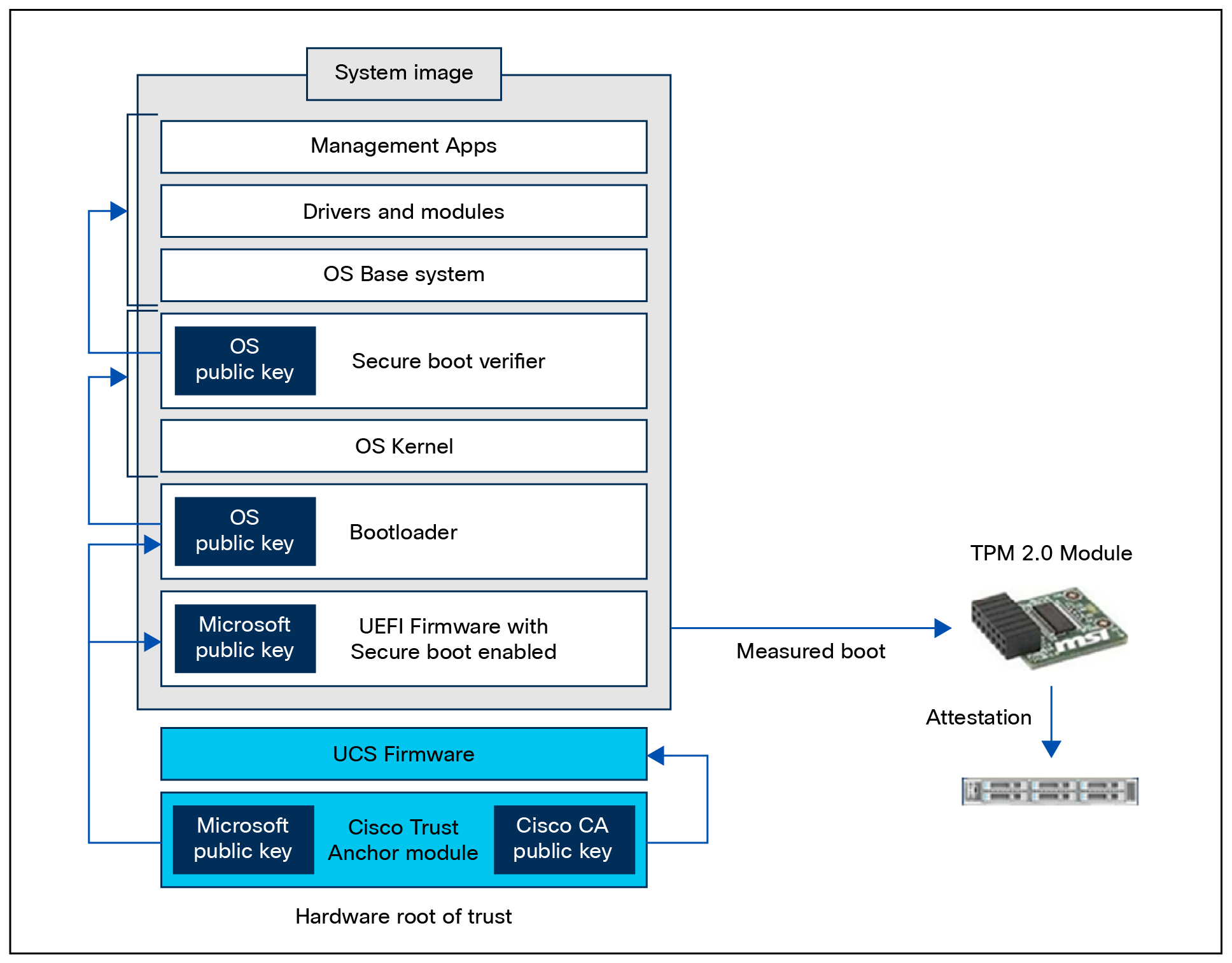
Use of Trust Anchor module and Trusted Platform module in the secure-boot process.
Cisco sources its TPMs from Infineon. The current Cisco UCS TPM modules are Infineon TMP SLB 9670 and SLB 9672.
Here’s a listing of the EAL certifications for Infineon TPMs: https://csrc.nist.gov/projects/cryptographic-module-validation-program/validated-modules/search?SearchMode=Basic&Vendor=infineon&CertificateStatus=Active&ValidationYear=0
The Infineon OPTIGA TPM SLB 9672 supports comprehensive self-tests as required by the TCG TPM 2.0 specification, using commands such as TPM2_SelfTest to verify integrity. Self-tests that are run on power-up or on-demand – with results retrieved through TPM2_GetTestResult and inField Upgrade Mode tests – are invoked to check the device status.
TPM 2.0 requires Cisco IMC versions 2.0(10) or later for support. The TPM modules used conform to TPM 2.0 as defined by the Trusted Computing Group (TCG), specifically the Infineon TPM SLB 9672 module is used in these platforms. TPM installation is supported after factory but is secured by a one-way screw and cannot be replaced or moved to another server. If a server with TPM is returned, the replacement must be ordered with a new TPM module.
Immutable identity
The secure unique device identifier, or SUDI, is an X.509v3 certificate that maintains the product identifier and serial number. The identity is implemented at manufacture of the product and is chained to a publicly identifiable root-certificate authority. The SUDI can be used as an unchangeable identity for configuration, security, auditing, and management.
The SUDI credential in the Trust Anchor module can be either RSA- or Elliptic Curve Digital Signature Algorithm (ECDSA)–based. The SUDI certificate, the associated key pair, and its entire certificate chain are stored in the tamper-resistant Trust Anchor module chip. Furthermore, the key pair is cryptographically bound to a specific Trust Anchor chip, and the private key is never exported. This feature makes cloning or spoofing the identity information virtually impossible.
The SUDI can be used for asymmetric key operations such as encryption, decryption, signing, and verifying that allow passage of the data to be operated upon. This capability makes remote authentication of a device possible. It enables accurate, consistent, and electronic identification of Cisco products for asset management, provisioning, version visibility, service entitlement, quality feedback, and inventory management.
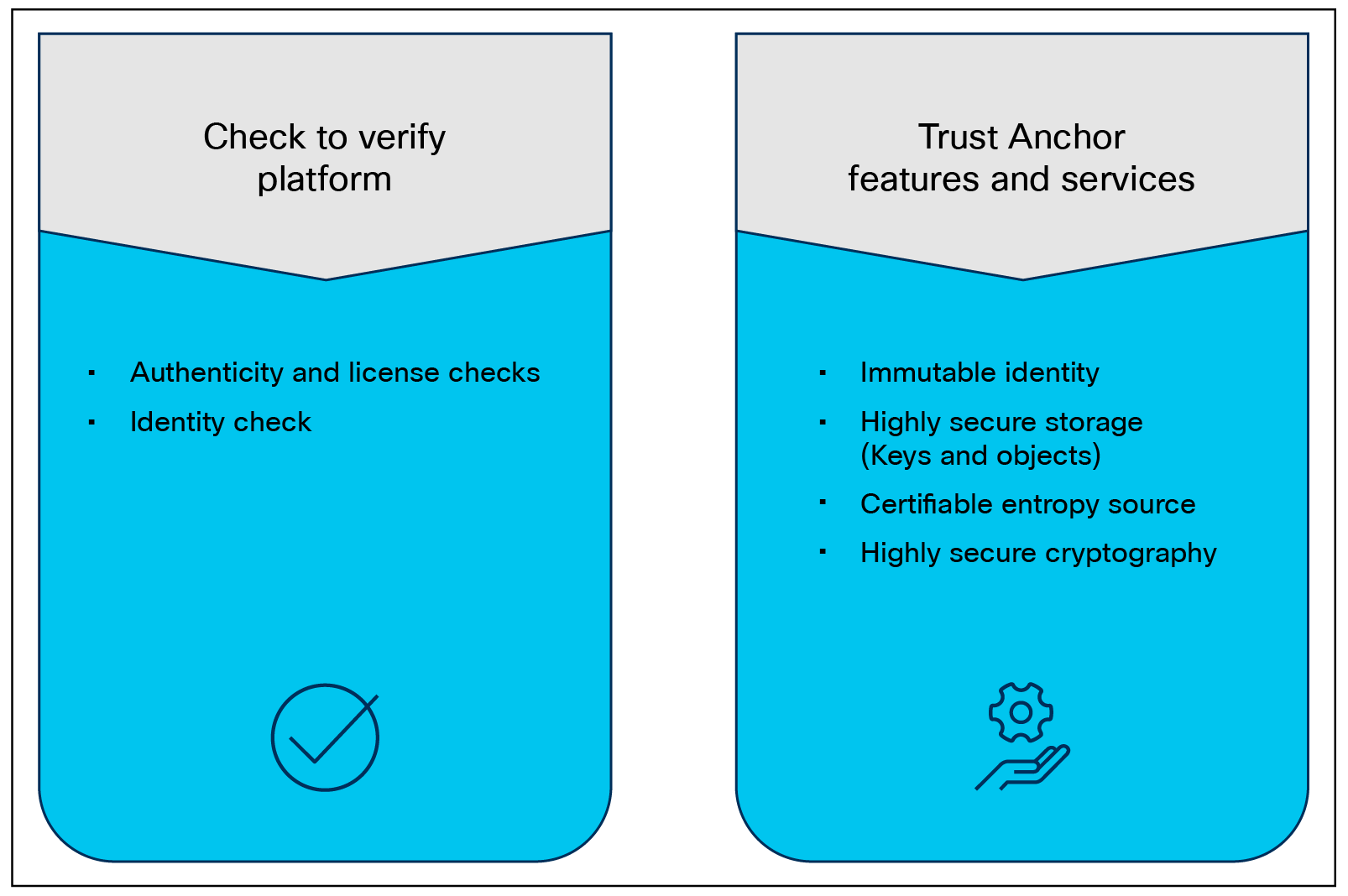
Trust Anchor module functions.
Currently the secure boot process, when enabled, is in effect during boot including both the system firmware and the installed operating system. The end-to-end security model that this enables, when combined with secure UI and CLI, encompasses the hardware Trust Anchor Module (TAM), to secure the system boot, to secure OS boot with externally verifiable attestation using the Trusted Platform Module (TPM).
This implementation covers the following:
● Secure boot, secured by public keys stored in the write-protected hardware root of trust
● Ensuring that only a trusted OS image, including drivers, is booted by verifying signatures
● Support of attestation of secure boot through TPM 2.0
The detailed process flow for a secure boot of the system and OS with attestation capability is shown below Note that the certificate-based hardware root of trust validates the Cisco UCS firmware, which ensures a clean BIOS that is set for key validation of the hypervisor bootloader, and so on. This guarantees that the hardware and hypervisor in the HX system have not been tampered with. External validation of this can be made through attestation using the TPM 2.0 in Cisco UCS.
Secure boot vendor key updates
When a vendor, such as Microsoft, updates or otherwise changes their secure signatures, these keys need to be updated on the UCS system to maintain secure boot operations. These updated certificates are embedded in the signed and secured Cisco UCS firmware. When the UCS system firmware is updated, these new keys are added, and secure boot continues to function. This is an ongoing process from various vendors and from Cisco and happens automatically.
See the following Tech Note that describes the update to the Microsoft Secure Boot Certificate that took place in 2026: https://www.cisco.com/c/en/us/support/docs/servers-unified-computing/unified-computing-system/225712-mitigate-microsoft-secure-boot.html
Cisco UCS systems have a variety of add-in cards that serve many different functions. These range from additional VICs, to NICs, DPU offload, GPU, and various HBAs. As part of a secure deployment posture, it is not only important to be able to securely boot the main system, including UEFI BIOS, the bootloader, and the operating system; the system must also securely boot the firmware that runs on the add-in cards themselves. To this end, most cards in use with Cisco UCS have a trust anchor built in that validates the card BIOS at card boot. These systems serve the same function as the TAM on the Cisco UCS motherboard in securing server firmware and ensuring legitimate code execution in system start up.
Runtime defenses (RTD) target injection attacks of malicious code into running software. Cisco runtime defenses include Address Space Layout Randomization (ASLR), Built-in Object Size Checking (BOSC), and X-space. Runtime defenses are complementary. Runtimes defenses do the following:
● They make it harder or impossible for attackers to exploit vulnerabilities in running software.
● They are complementary; you can implement them individually or deploy several runtime defenses together.
Cisco UCS supports both Intel and AMD processors. The latest generations of these CPUs and their accompanying chipsets have extensions and programmatic capabilities around memory encryption and secure code execution and isolation.
Intel Boot Guard
Intel Boot Guard (4th Gen CPU and greater) is a security technology designed to enhance the integrity of the boot process and protect against unauthorized firmware and bootloader modifications on systems using Intel processors. It is part of Intel's broader security initiatives to safeguard the boot process from potential threats and ensure the system starts up securely. Here are the key aspects of Intel Boot Guard:
● Boot process integrity:
Intel Boot Guard focuses on protecting the boot process, ensuring that the system starts up using only authorized and unaltered firmware and bootloader components.
● Hardware-based protection:
Intel Boot Guard operates at the hardware level, utilizing a combination of hardware-based mechanisms within the Intel chipset and processor.
● Verified boot:
During the boot process, Intel Boot Guard verifies the digital signature of the firmware and bootloader components before allowing them to execute. Digital signatures are used to verify the authenticity and integrity of the firmware and bootloader code.
● Measures against unauthorized modifications:
Intel Boot Guard helps prevent unauthorized modifications to the firmware and bootloader, protecting against various attacks that attempt to inject malicious code or compromise the boot process.
● Key rollback protection:
To prevent attacks that involve rolling back to a previously signed firmware version with known vulnerabilities, Intel Boot Guard includes protections against key rollback.
● Configurability:
System manufacturers have some flexibility in configuring Intel Boot Guard based on their specific security requirements. They can, for example, decide which firmware and bootloader components are subject to verification.
● Integration with secure boot:
Intel Boot Guard works in conjunction with other security technologies, such as UEFI Secure Boot. Secure boot ensures that only signed and authenticated code is allowed to run during the boot process.
● OEM customization:
Original Equipment Manufacturers (OEMs) can customize Intel Boot Guard policies to align with their specific security needs, allowing them to adapt the technology to their hardware implementations.
It's important to note that while Intel Boot Guard enhances system security, it is just one component of a comprehensive security strategy. Secure firmware, secure boot, and other security features collectively contribute to creating a more resilient and secure computing environment. Additionally, the specifics of Intel Boot Guard may vary among different Intel processor generations, so it's advisable to refer to Intel's official documentation for the most accurate and up-to-date information.
Figure 12 shows where to set BIOS tokens to enable Intel TEE (Trusted Execution Environment) directives.
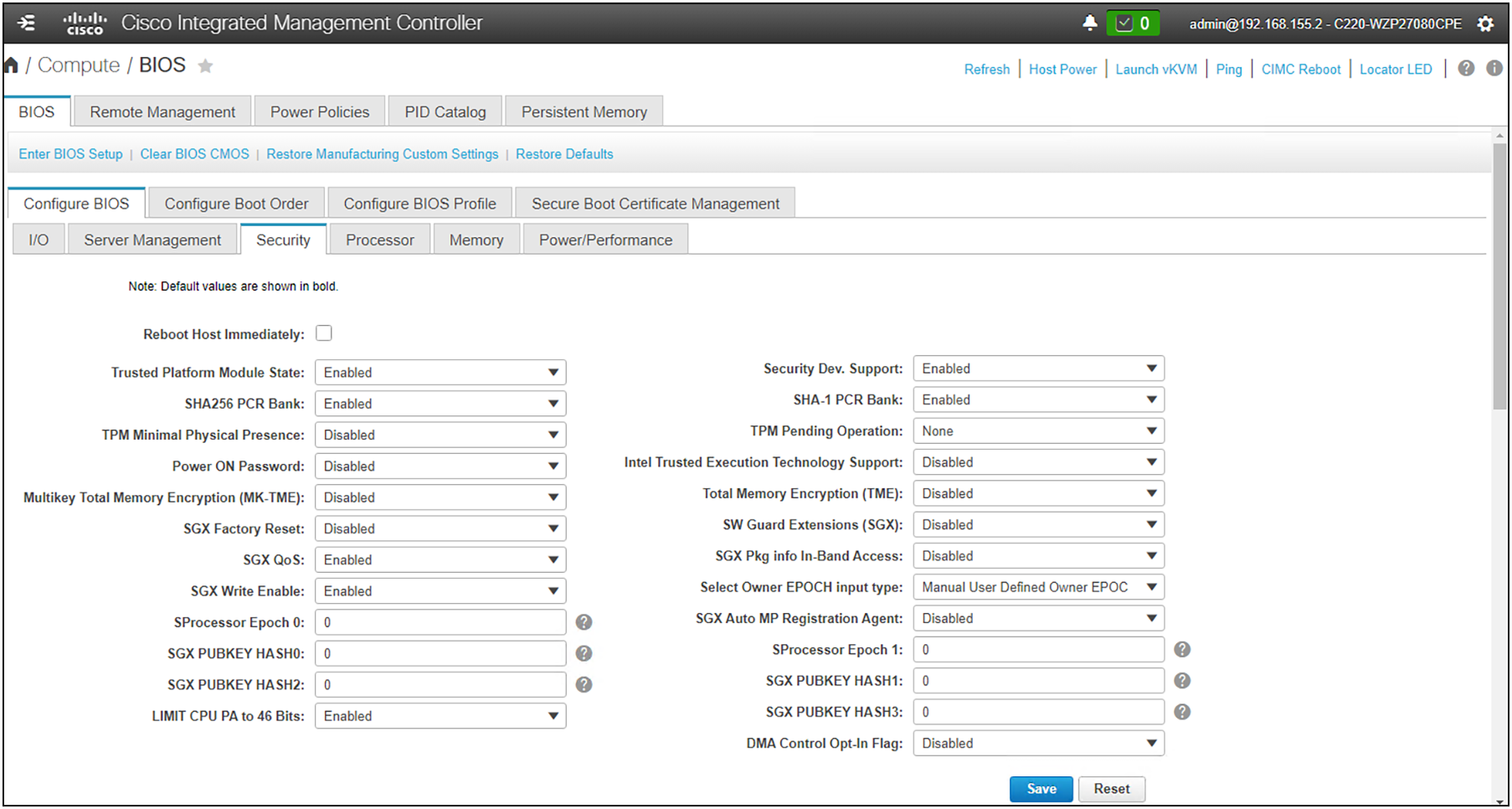
BIOS tokens available to effect secure processor directives
AMD Platform Secure Boot
AMD Platform Secure Boot (PSB) is a security feature designed to enhance the security of AMD processors and platforms by focusing on the boot process. PSB is part of AMD's security initiatives to protect against unauthorized code execution during the system boot-up process.
Key features of AMD Platform Secure Boot include:
● Secure boot mechanism:
◦ PSB is a secure boot mechanism that ensures the integrity of the boot process by verifying the authenticity of firmware and bootloader components before allowing them to execute.
● Protection against unauthorized code execution:
◦ PSB helps protect the system from threats related to unauthorized or malicious code attempting to run during the boot sequence.
● Integration with industry standards:
◦ PSB is designed to work in conjunction with industry-standard secure boot protocols, such as UEFI (Unified Extensible Firmware Interface) secure boot.
● Chain of trust:
◦ PSB establishes a chain of trust from the initial firmware load through the bootloader and into the operating system, ensuring that each step in the boot process is verified and secure.
● Cryptographic verification:
◦ Cryptographic methods, such as digital signatures, are used to verify the authenticity and integrity of firmware and bootloader code. Only code with valid signatures is allowed to run.
● Protection against rootkits and bootkits:
◦ By securing the boot process, PSB helps defend against certain types of attacks, including rootkits and bootkits, which aim to compromise the system at an early stage of boot-up.
● OEM customization:
◦ Original Equipment Manufacturers (OEMs) can configure and customize PSB settings based on their specific security requirements. This flexibility allows OEMs to adapt the security features to their hardware implementations.
● Secure deployment of virtualization:
◦ In virtualized environments, PSB can contribute to the security of the hypervisor and virtual machines by ensuring a secure boot process for the entire virtualization stack.
It's important to note that the specifics of PSB and its integration with different processor generations may vary. For the most accurate and up-to-date information about AMD Platform Secure Boot, refer to AMD's official documentation. Security features are continually evolving, and AMD may introduce enhancements or updates to its security technologies over time.
Security Protocol and Data Model
To defend against attacks targeting mutable components in Cisco UCS systems, the Security Protocol and Data Model (SPDM) specification enables a secure transport implementation that challenges a device to prove its identity and the correctness of its mutable component configuration. This feature is supported on Cisco UCS servers starting with Cisco UCS Manager Release 4.2(1d).
SPDM defines messages, data objects, and sequences for performing message exchanges between devices over a variety of transport and physical media. It orchestrates message exchanges between Baseboard Management Controllers (BMC) and endpoint devices over a Management Component Transport Protocol (MCTP). Message exchanges include authentication of hardware identities accessing the BMC. SPDM enables access to low-level security capabilities and operations by specifying a managed level for device authentication, firmware measurement, and certificate management. Endpoint devices are challenged to provide authentication, and BMC authenticates the endpoints and allows access only for trusted entities.
The Cisco UCS Manager optionally allows uploads of external security certificates to BMC. A maximum of 40 SPDM certificates is allowed, including native internal certificates. Once the limit is reached, no more certificates can be uploaded. User uploaded certificates can be deleted but internal/default certificates cannot.
An SPDM security policy allows you to specify one of three security-level settings. Security can be set at one of the three levels listed below:
● Full Security
◦ This is the highest MCTP security setting. When you select this setting, a fault is generated when any endpoint authentication failure or firmware measurement failure is detected. A fault will also be generated if any of the endpoints do not support either endpoint authentication or firmware measurements.
● Partial Security (default)
◦ When you select this setting, a fault is generated when any endpoint authentication failure or firmware measurement failure is detected. There will NOT be a fault generated when the endpoint doesn’t support endpoint authentication or firmware measurements.
● No Security
◦ When you select this setting, there will NOT be a fault generated for any failure (either endpoint measurement or firmware measurement failures).
You can also upload the content of one or more external/device certificates into BMC. Using an SPDM policy allows you to change or delete security certificates or settings as desired. Certificates can be deleted or replaced when no longer needed.
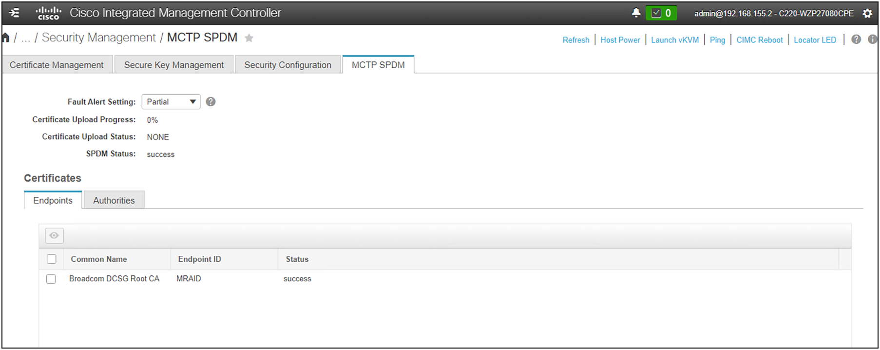
MCTP SPDM configuration in CIMC.
The password-strength option is enabled by default on all management modes. Strong passwords must meet the following requirements:
● Must contain a minimum of 8 characters and a maximum of 64 characters.
● Must contain at least three of the following:
◦ Lowercase letters
◦ Uppercase letters
◦ Numbers
◦ Special characters
● Must not contain a character that is repeated more than three times consecutively (for example, aaabb).
● Must not be identical to the username or the reverse of the username.
● Must pass a password dictionary check. For example, the password must not be based on a standard dictionary word.
● Must not contain the following symbols: $ (dollar sign), ? (question mark), or = (equals sign).
● Should not be blank for local user and admin accounts.
Additional password profile options:
● Change Count: maximum times a password can be changed within the Change Interval
● Change Interval: time frame used by the Change Count
● No Change Interval: minimum hours a local user must wait before changing a newly created password
● Change During Interval: ability to change the password during the Change Interval
After deployment and initial configuration are complete, make sure that any default passwords are changed or updated and that expiration times are set.
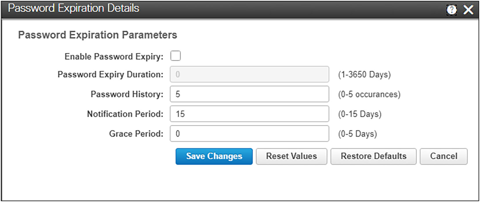
Setting and changing the expiration of a local user password
Multifactor Authentication (MFA)
Cisco UCS supports two-factor authentication (2FA) with LDAP or RADIUS.
To use 2FA with LDAP, you need to integrate a third-party 2FA service (such as Duo, Okta, or Azure MFA) as a proxy between CIMC and the LDAP server, where the CIMC first sends credentials to the 2FA service, which then verifies the user's identity through LDAP and prompts the user for a second factor (such as a code from the user’s phone) before granting access; essentially, LDAP itself doesn't handle 2FA natively, so you need an external solution to add this functionality.
Key steps to implement 2FA with LDAP:
● Choose a 2FA provider: select a reputable 2FA service that supports LDAP integration.
● Configure the 2FA service:
◦ Set up your LDAP server details within the 2FA provider's settings.
◦ Define which user groups or attributes should be subject to 2FA.
● Configure your application:
◦ When a user attempts to log in, the application will redirect them to the 2FA provider for verification.
How it works in practice:
● User login attempt: user enters a username and password on the application.
● Authentication request to 2FA provider: the application sends the credentials to the 2FA service.
● LDAP verification: the 2FA service queries the LDAP server to verify the username and password.
● 2FA challenge: if the credentials are valid, the 2FA service prompts the user for a second factor (for example, a code from the user’s phone app).
● Access granted: once the user successfully provides the second factor, the 2FA service grants access to the application.
Important considerations:
● Security: ensure that the connection between your application and the 2FA provider is encrypted using TLS.
● Management: regularly review and update your 2FA policies and settings as needed.
With the Duo implementation, MFA is performed through the Duo Authentication Proxy, which is an on-premises software service that receives authentication requests from local devices and applications through RADIUS or LDAP, optionally performs primary authentication against your LDAP directory or RADIUS authentication server, and then contacts Duo to perform secondary authentication. Once the user approves the two-factor request, which is received as a push notification from Duo Mobile, or as a phone call, etc., the Duo proxy returns access approval to the device or application that requested authentication.
Access methods to management and configuration interfaces
The management plane consists of functions that achieve the management goals of the system. Any management function undertaken by the user must rely on interaction through secure protocols, whether the user is managing through CLI or UI. This is handled through HTTPS for any UI access, whether UCSM, CIMC, or SaaS-based Cisco Intersight. Authenticated, tokenized access is used for in-house development through API. SSH for encrypted command line access is also supported. Management security also entails role-based access control as well as auditing and logging of system activities and user input, all of which are incorporated into every management mechanism.
Interactive management sessions using the command line take advantage of SSH or SCP. This is available for UCSM or standalone CIMC deployments. These sessions take place in the embedded and abstracted management shell. This shell is hardened, does not allow root access, and cannot run user-space applications.
Role-Based Access Control (RBAC)
Role-Based Access Control is a method of restricting or authorizing system access for users based on user roles and locales. A role defines the privileges of a user in the system and the locale defines the organizations (domains) that a user is allowed access. Because users are not directly assigned privileges, management of individual user privileges is simply a matter of assigning the appropriate roles and locales.
Local authentication is enabled by default. Local users are restricted to three roles:
● Admin
● User
● Read-only
Local user management is assigned in the User Management section of the CIMC UI.
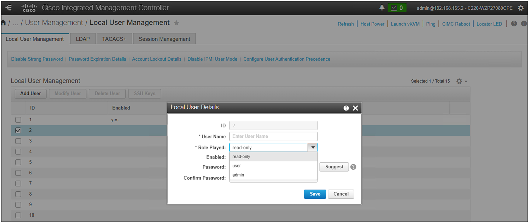
Defining local users in CIMC.
Use HTTPS and SSH for maximum security when accessing a Cisco UCS device. Numerous authentication methods provide enhanced security. There is a maximum of 48 local user accounts. Remote authentication uses LDAP, RADIUS, and TACACS+ with a maximum of 16 TACACS+ servers, 16 RADIUS servers, and 16 LDAP providers for a total of 48 providers. Roles defined in these domains are used to restrict and define access for different users. Refer to the deployment and configuration guides for your specific management RBAC configurations (UCSM, Intersight, and local CIMC).
Authentication domains
An authentication domain in UCS systems is used to leverage multiple authentication schemas. It allows you to specify and configure different authentication methods during login, or use the default authentication service configuration.
The default (local) authentication and the console authentication can utilize different providers. Furthermore, authentication grouping uses a maximum of 16 groups and a maximum eight providers per group. The provider’s authentication ordering method provides flexibility on what providers to use and what backups will be in place. The default authentication ports are configurable.
SSL key management – UI certificates and self-encrypting drives
Cisco UCS ships with a self-signed certificate using a default 1024 length key pair. To employ a more secure method, use trusted third-party certificates from a trusted source that affirms the identity of the Cisco UCS device. You can configure the CIMC certificate in Certificate Management in the CIMC UI under Security Management.
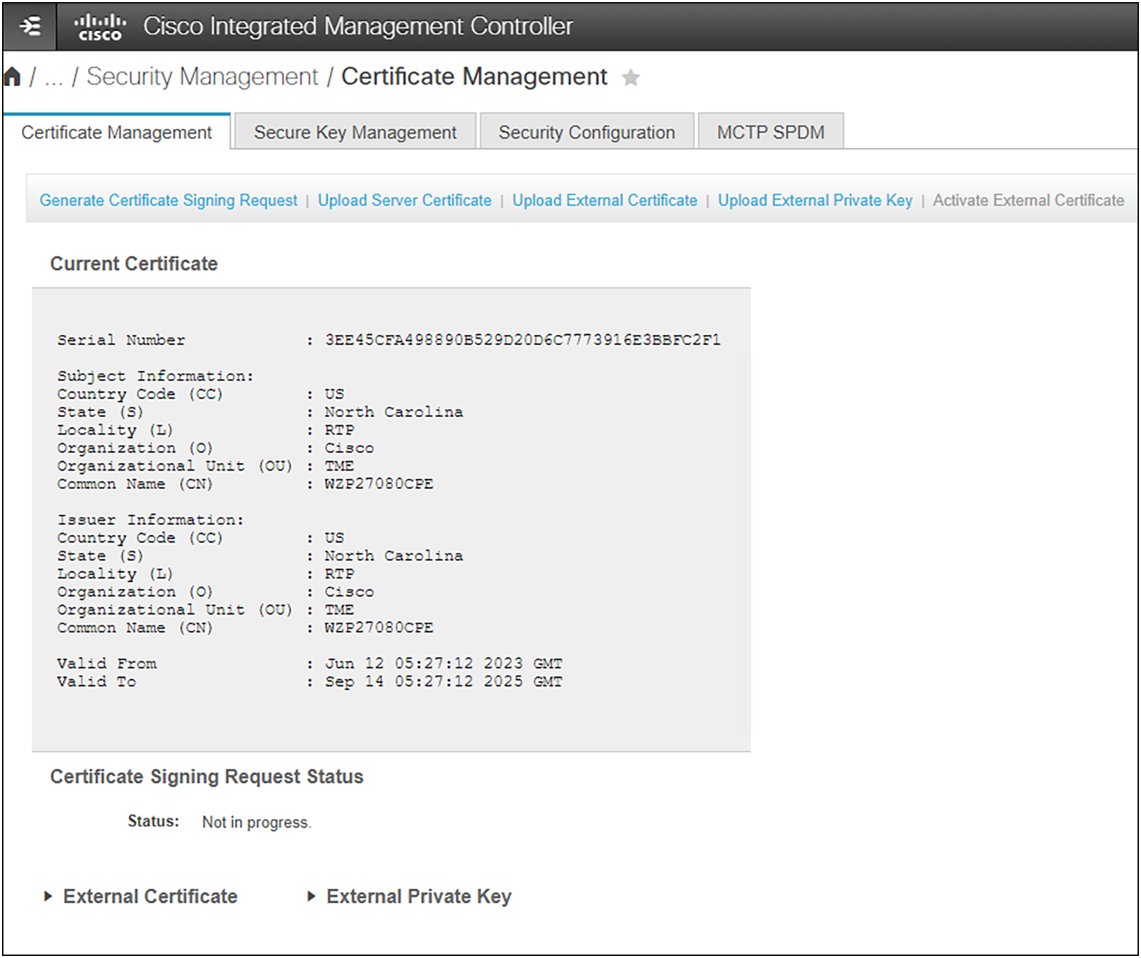
Setting up system certificates in CIMC.
Key management is also a core function for Self-Encrypting Drives (SEDs). SED keys can be managed either locally or remotely with a third-party key-management server such as CipherTrust. Local key management requires a security key (passphrase) to be entered into the system. Remote key management requires configuration of the Key Management Server (KMS) and the proper distribution of certificates and public and private keys.
In CIMC, you configure the SED key management under the Secure Key Management UI in the Security Management section.
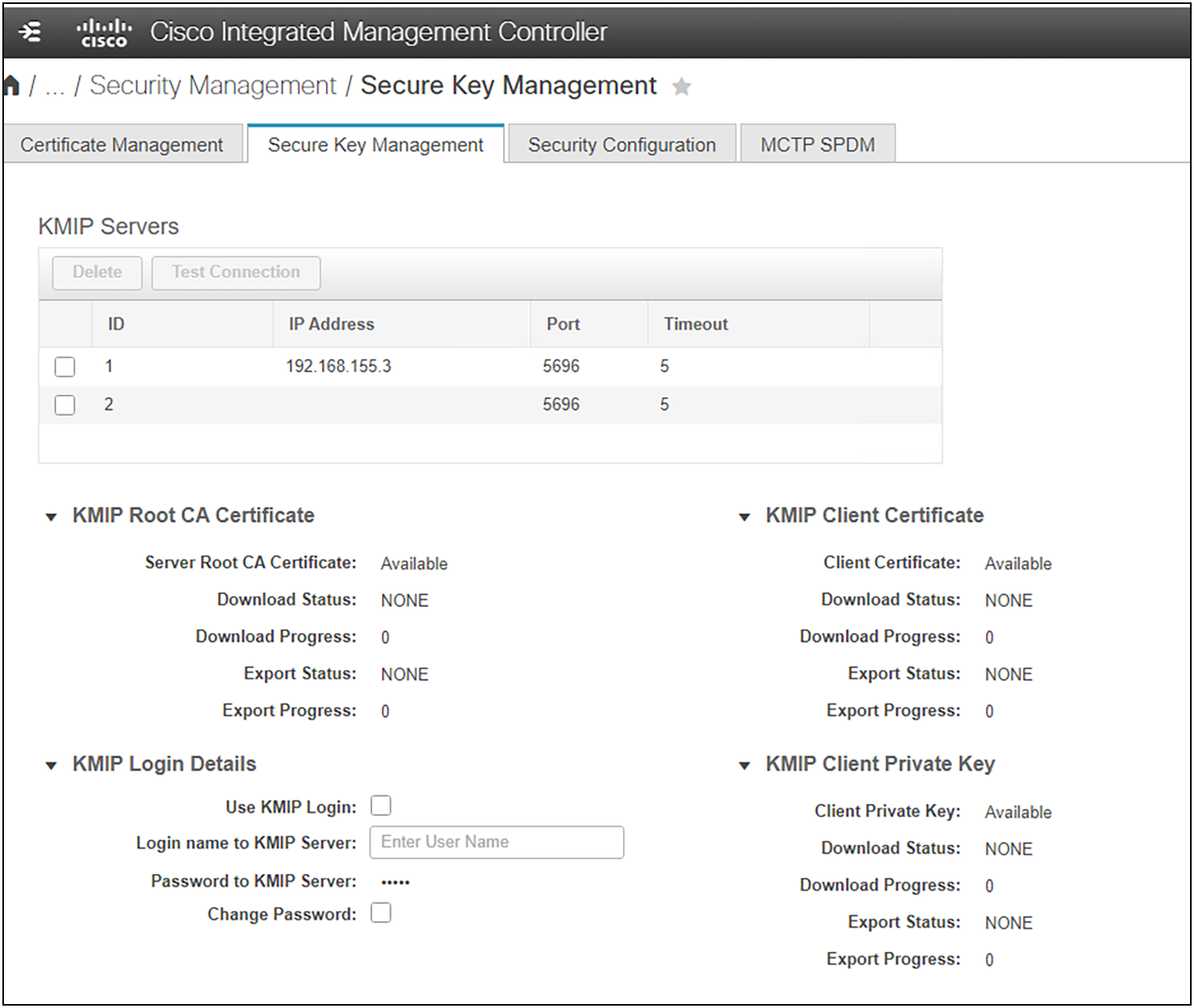
Configure key management for Self-Encrypting Drives (SEDs) in CIMC
Cisco Integrated Management Console
Cisco UCS servers in standalone mode are managed using the baseboard management console, also called the Cisco Integrated Management Console (CIMC). Cisco UCS C-Series rack-mount servers ship with CIMC firmware.
Automation without UCSM
CIMC is a separate management module built into the motherboard. A dedicated ARM-based processor, separate from the main server’s CPU, runs the CIMC firmware. The system ships with a running version of the CIMC firmware. You can update the CIMC firmware, but no initial installation is needed.
You can use a web-based GUI or SSH-based CLI or an XML-based API, or Redfish API to access, configure, administer, and monitor the server. Almost all tasks can be performed in any interface, and the results of tasks performed in one interface are displayed in another. However, you cannot do the following:
● Use CIMC GUI to invoke CIMC CLI
● View a command that has been invoked through CIMC CLI in CIMC GUI
● Generate CIMC CLI output from CIMC GUI
You can use CIMC to perform the following server management tasks:
● Power on, power off, power cycle, reset and shut down the server
● Toggle the locator LED
● Configuring BIOS settings
● Configure the server boot order
● View server properties and sensors
● Manage remote presence
● Create and manage local user accounts, and enable remote user authentication through active directory
● Configure network-related settings, including NIC properties, IPv4, VLANs, and network security
● Configure communication services, including HTTP, SSH, IPMI Over LAN, and SNMP
● Manage certificates
● Configure platform event filters
● Update CIMC firmware
● Monitor faults, alarms, and server status
● Set time zone and view local time
● Install and activate CIMC firmware
● Install and activate BIOS firmware
CIMC provisions servers and, as a result, exists below the operating system on a server; therefore, you cannot use it to provision or manage operating systems or applications on servers.
The CIMC CLI is a command-line management interface for Cisco UCS C-Series servers. You can launch the CIMC CLI and manage the server over the network by SSH or Telnet. By default, Telnet access is disabled.
A user of the CLI will be one of three roles: admin, user (can control, cannot configure), and read-only.
Cisco UCS IMC REST-based API
Representational State Transfer (REST) or RESTful web services allow you to provide interoperability between systems on the internet. Using REST-compliant web services, you can access and manipulate web resources using a uniform and predefined set of stateless operations. Cisco has developed REST API capabilities to configure Cisco UCS C-series servers using Redfish technology.
Redfish is an open industry standard specification and schema that specifies a RESTful interface and utilizes JSON and OData to help customers integrate solutions within their existing tool chains. Redfish is sponsored and controlled by Distributed Management Task Force, Inc. (DMTF), a peer-review standards body recognized throughout the industry.
Use the aaaLogin method to get a valid cookie. Use aaaRefresh to maintain the session and keep the cookie active. Use the aaaLogout method to terminate the session (also invalidates the cookie). A maximum of 256 sessions in Cisco UCS can be opened at any one time.
Securing communications
The first step in securing network communications with CIMC is to complete the NIC-addressing and properties configuration page. This is in the Network section under Networking in the navigation menu on the left.
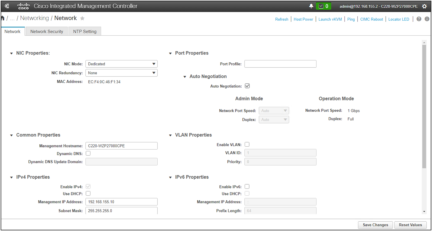
Setting general NIC properties
The next tab allows you to configure IP blocking and filtering policies. This allows you to restrict the addresses and/or networks that are allowed to connect, log in, and administer the server through CIMC.
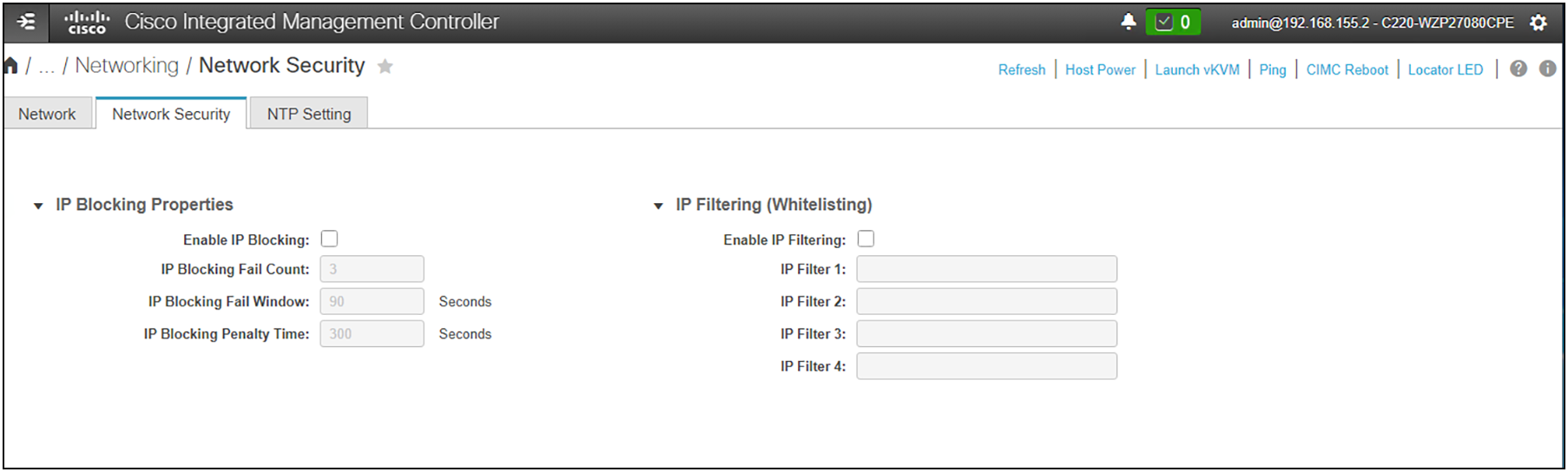
Enabling IP security through blocking and filtering
Once the basics of connectivity and filtering are configured, you should set the communication services protocol preferences. Here you can select and customize service ports and cryptographic ciphers as well as manage the availability of the XML and Redfish APIs.
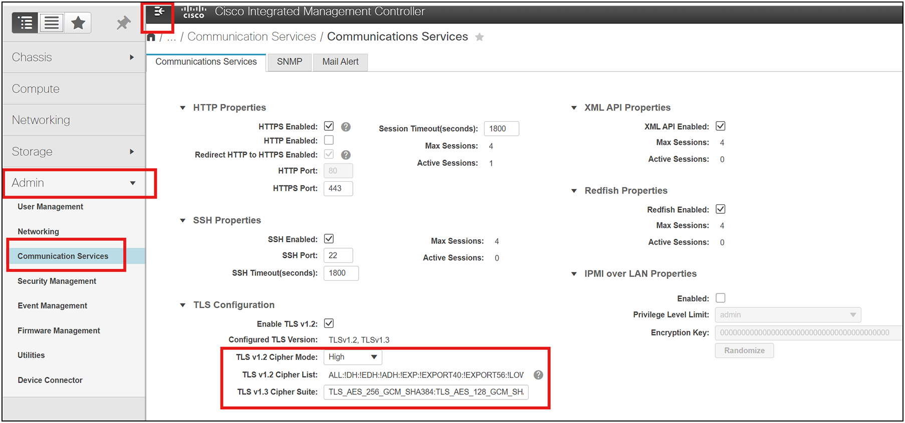
Selecting secure communication protocols
You should note that if you do not want to manually select ciphers, it is recommended to enable FIPS and then Common Criteria (CC) mode in the Security Configuration tab. FIPS must be enabled before Common Criteria, because it is a subset of the CC requirements. Enabling these will automatically set the system in compliance with strict federal secure communication standards and enable/disable cipher sets.
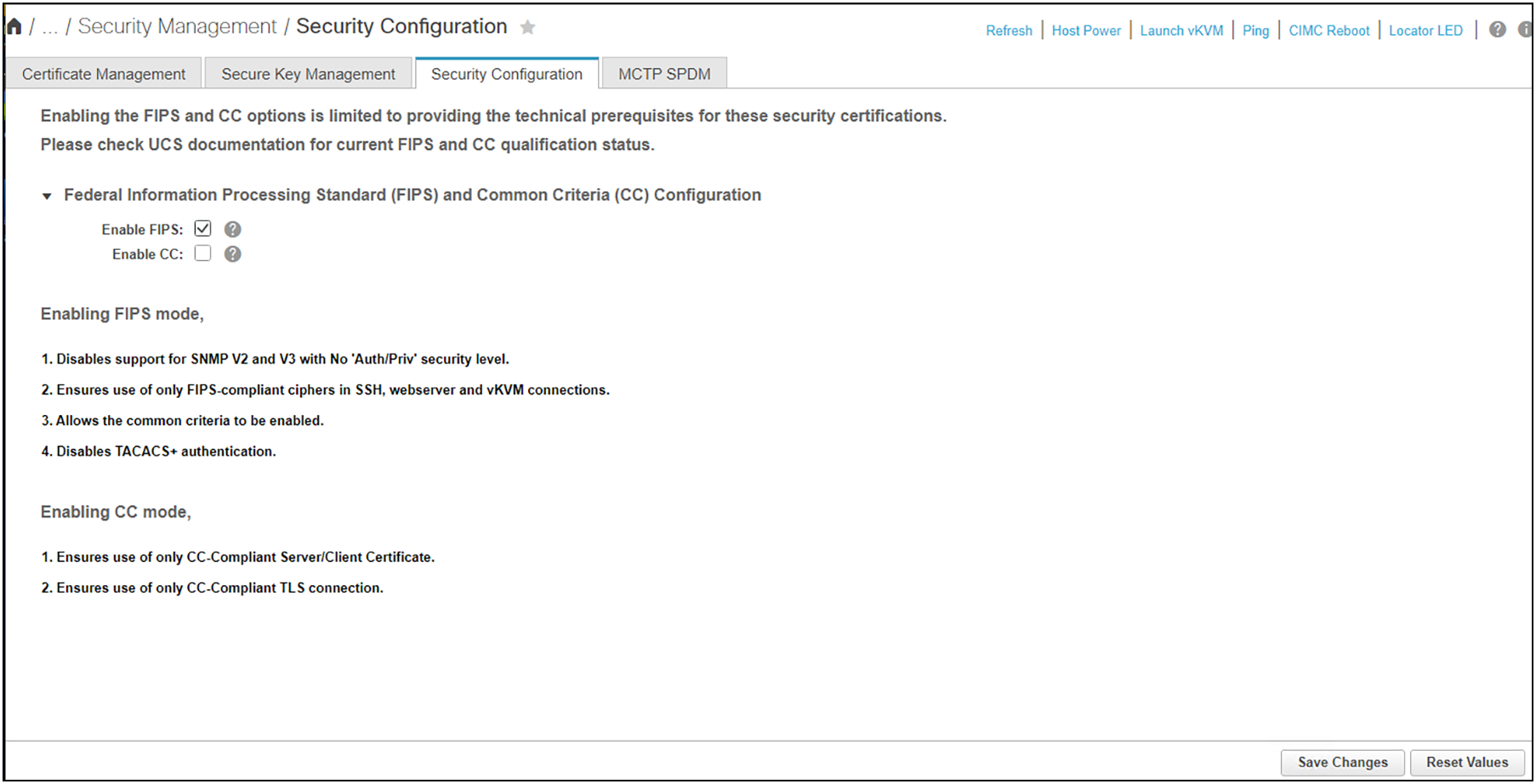
Enable FIPS and then CC mode for cipher selection and authentication protections
Finally, be sure to set accurate NTP server settings. This ensures that any authentication services you may be using (for example, LDAP with Active Directory) has the correct, nonexpired time stamps on challenge requests. Inaccurate times may invalidate authentication requests before you can even use them.
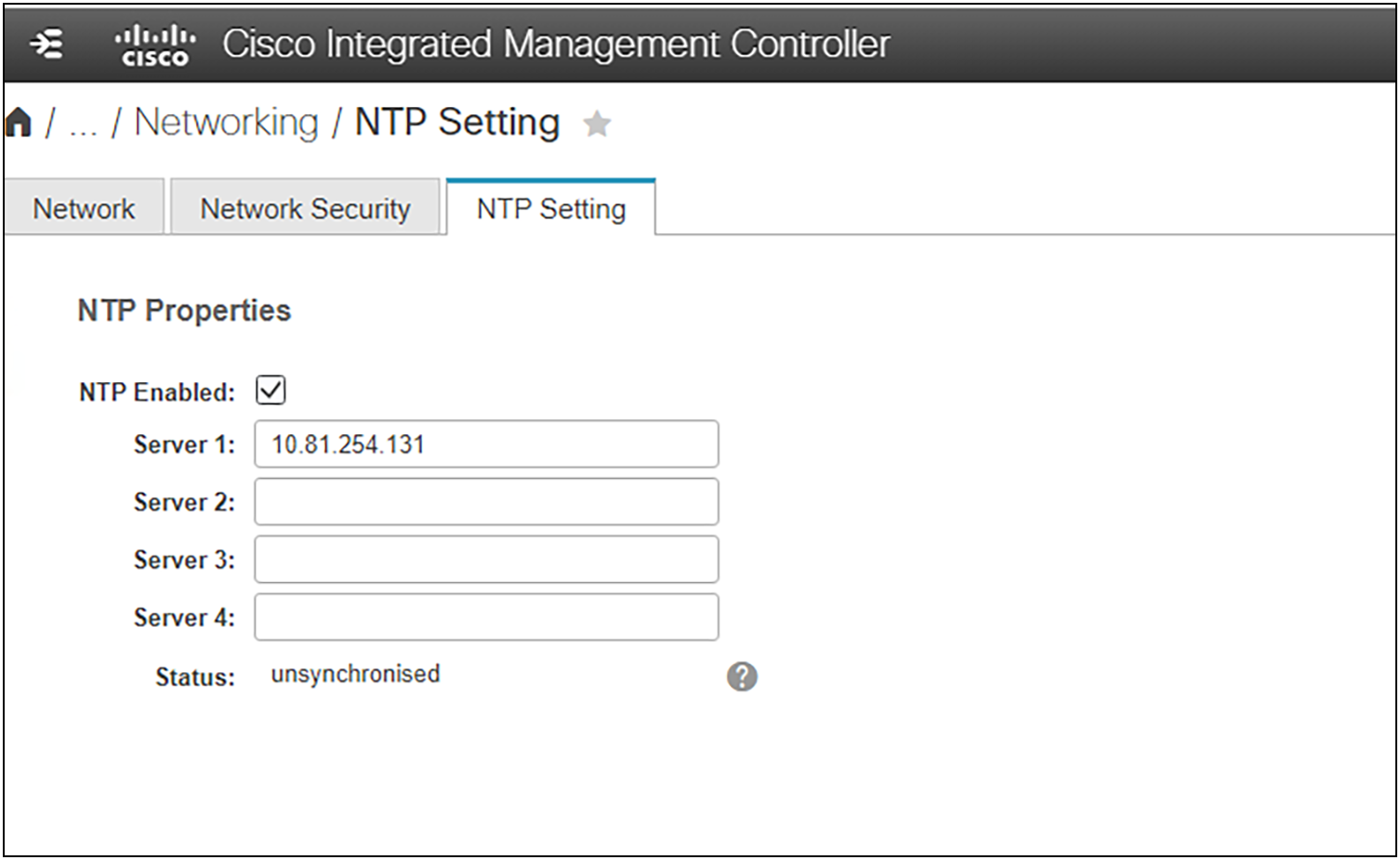
Setting NTP. This is critical for time-sensitive authentication mechanisms.
Viewing User Sessions
User sessions can be viewed and terminated (when not opened using Serial Over LAN [SOL]). The procedure below details the process.
| Step 1 |
In the Navigation pane, click the Admin menu. |
|
| Step 2 |
In the Admin menu, click User Management. |
|
| Step 3 |
In the User Management pane, click Session Management. |
|
| Step 4 |
In the Sessions pane, view the following information about current user sessions: |
|
| Name |
Description |
|
| Session ID column |
The unique identifier for the session |
|
| BMC Session ID |
The identifier for the BMC session |
|
| User Name column |
The username for the user |
|
| IP Address column |
The IP address from which the user accessed the server. If this is a serial connection, it displays N/A. |
|
| Session Type column |
The type of session the user chose to access the server. This can be one of the following:
●
webgui— indicates the user is connected to the server using the web UI
●
CLI— indicates the user is connected to the server using CLI
●
serial— indicates the user is connected to the server using the serial port
|
|
| Action column |
This column displays N/A when the SOL is enabled and Terminate when the SOL is disabled. You can terminate a session by clicking Terminate on the web UI. |
|
About CiscoSSH
CiscoSSH is a common module, based on Linux and enhanced by Cisco, that is derived from OpenSSH (and pkix-ssh). It enables Cisco products to achieve FIPS compliance when used with the CiscoSSL FIPS Object Module (FOM) or a FIPS-capable OpenSSL.
Most scanners that users run to scan for security vulnerabilities (CVEs) are not sophisticated enough to look at the backing code used in two-factor authentication. Typically, security scanners use version information to alert users to possible security issues. Since CiscoSSH is a fork of multiple open-source upstream code bases, these can be inaccurate. OpenSSH, for example, does not branch. OpenSSH has a single mainline branch, and new releases are derived from there. This means security patches are applied to the main branch and released as a new version. OpenSSH does not backport CVE fixes or security patches. However, the CiscoSSH team does backport CVE patches when possible.
What does this mean for security scanners? It means the scanner's reports are often incorrect when based solely on a version of OpenSSH. Please validate the CVE information with Cisco to see when and if a particular security patch has been implemented and released. Also, please note the “fixed” version information, because it is likely to be different from what the security scanner reports.
Middlebox compatibility mode
During development of the TLSv1.3 standard, it became apparent that, in some cases, even if a client and server both support TLSv1.3, connections could sometimes still fail. This is because middleboxes on the network between the two peers do not understand the new protocol and prevent the connection from taking place. In order to work around this problem, the TLSv1.3 specification introduced “middlebox compatibility mode.” This made a few optional changes to the protocol to make it appear more like TLSv1.2 so that middleboxes would let it through.
Middlebox compatibility mode makes the TLSv1.3 handshake flow look more like a TLSv1.2 handshake. This is accomplished by filling in legacy fields in handshake messages and by sending a TLSv1.2 handshake message eliminated from the pure TLSv1.3 implementation. See the information on Middlebox compatibility mode here: Middlebox compatibility mode.
These changes are largely superficial in nature but do include sending some small but unnecessary messages. OpenSSL has middlebox compatibility mode on by default, so most users should not need to worry about this. However, applications may choose to switch it off by calling the function SSL_CTX_clear_options() and passing SSL_OP_ENABLE_MIDDLEBOX_COMPAT as an argument.
If the remote peer is not using middlebox compatibility mode and there are problematic middleboxes on the network path, then this could cause spurious connection failures.
OpenSSL/CiscoSSL supports middlebox compatibility, but UCSM and CIMC provide no means to disable it. Keeping this option enabled prevents communication problems with applications that do not use the TLS 1.3 protocol per se and rely on some of these TLS 1.2 fields to exist in order to function. This does not break TLS 1.3.
It is important to note that UCSM and CIMC do not use OpenSSL; they use CiscoSSL. Similar to CiscoSSH, the CiscoSSL module is developed by Cisco in-house, based on OpenSSL. See the “About CiscoSSH” section, above, for details.
User authentication
There are three primary user authentication methods for CIMC: local user, LDAP, and TACACS+. Secure LDAP is the recommended method for user authentication for the following reasons:
● Improved security: secure LDAP authentication helps prevent unauthorized access by using encrypted communications.
● Easy management: LDAP allows for centralized management of user credentials and authorization.
● Robust RBAC: LDAP provides granular user controls.
● Scalability: LDAP supports dynamic group authorization, allowing for efficient management of large numbers of users.
● Integration: CIMC supports both LDAP and Microsoft Active Directory, enabling seamless integration with existing directory services.
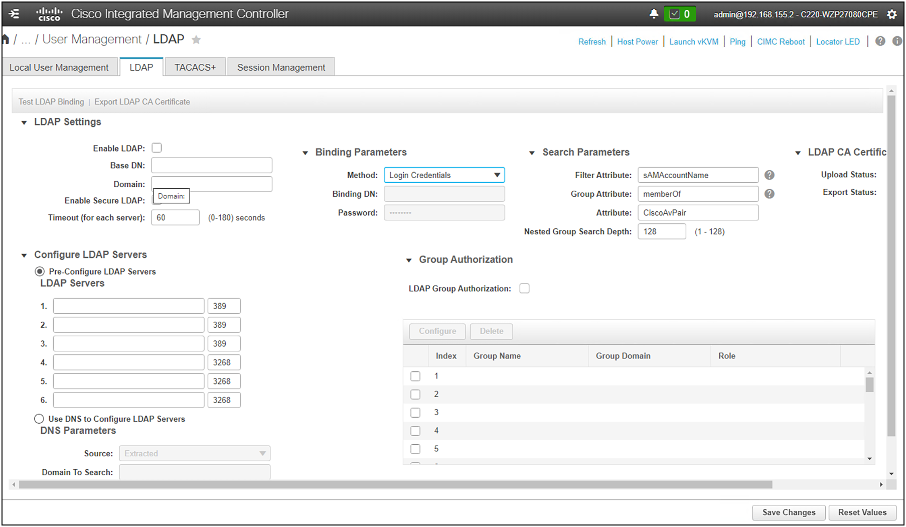
LDAP configuration
If you have more than one authentication method deployed with your server(s), you can select authentication precedence. By assigning authentication priority, you can ensure that one method is tried before another. For example, if are running secure LDAP and have local user authentication enabled, you can prioritize LDAP over local user authentication. The system will attempt to authenticate users through LDAP first, then fall back to local users if the service is unavailable.
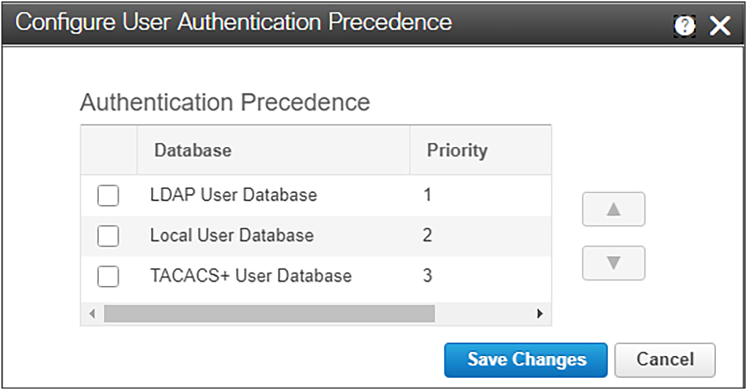
Authentication precedence when more than one mechanism is configured
Server system monitoring is crucial for security because it provides real-time visibility into the performance, health, and activities of servers within an IT infrastructure. Monitoring helps identify and respond to potential security threats, vulnerabilities, and irregularities, contributing to a proactive and effective security posture. Effective monitoring provides the following:
● Early detection of anomalies
◦ Detects abnormal patterns or behaviors on servers, which may indicate a security incident. Early detection allows for a quicker response to potential threats.
● Identification of security incidents
◦ Identifies security incidents such as unauthorized access, malware infections, or suspicious network activities
● Visibility into system health
◦ Provides insights into the overall health and performance of servers. A sudden drop in performance or unexpected system behavior may indicate a security compromise or the presence of malicious activities.
● Alerts and notifications
◦ Generates alerts and notifications when predefined thresholds or security policies are breached
● Resource utilization monitoring
◦ Unusual spikes in CPU, memory, or network usage may indicate a security incident, such as a denial-of-service attack or a compromised system engaging in malicious activities.
● Log analysis for security events
◦ Analyzes server logs for security-related events. This includes authentication attempts, access logs, and error messages that may reveal signs of unauthorized access or other security incidents.
● User activity monitoring
◦ Monitoring user activities on servers helps in detecting suspicious behavior, such as unauthorized access or privileged users performing unexpected actions.
● Compliance and auditing
◦ Server monitoring helps provide the necessary data for audits. It verifies that security policies are enforced and that systems are in compliance with industry or organizational standards.
● Incident response and forensics
◦ In the event of a security incident, monitoring data serves as valuable forensic evidence. It helps security teams understand the nature of the incident, trace its origins, and implement corrective measures to prevent future occurrences.
● Patch and update management
◦ Monitoring systems can track the status of server patching and updates. Ensuring that servers are up to date on security patches is essential for protecting against known vulnerabilities.
● Capacity planning for security resilience
◦ Monitoring assists in capacity planning, allowing organizations to anticipate resource demands and ensuring that servers are equipped to handle security-related loads, such as increased traffic during a DDoS attack.
By actively monitoring server systems, organizations can enhance their ability to prevent, detect, and respond to security threats effectively. It is a foundational element of a comprehensive security strategy, providing the insights needed to maintain a secure and resilient IT environment.
Standalone Cisco UCS C-Series servers monitoring background
Monitoring support for our standalone Cisco UCS C-Series servers has evolved with each release. We have documented the internals of our monitoring subsystem in the graphic in Figure 25.
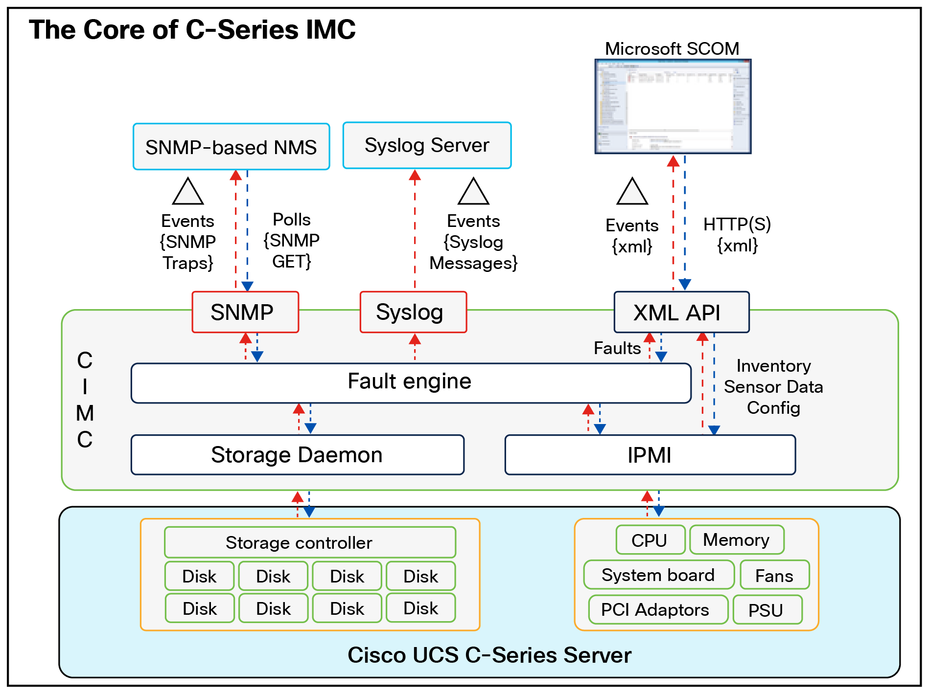
IMC monitoring engine.
Faults: SNMP and mail alerts
The standalone Cisco C-Series servers’ fault engine has become a central repository and clearinghouse for fault data as it is passed along to monitoring endpoints. The fault engine acts as a master repository for events within the system and initiates alerts (SNMP traps, syslog messages, XML API events, etc.); it can also be queried through SNMP (GETs) or the XML API. This durability of fault information provides users a mechanism to not only receive fault data but also use these interfaces to query system health data.
Within the system, the fault engine regularly polls components’ health status in the form of sensor data using IPMI and the storage daemon, and these values are compared to threshold reference points. If a sensor value is outside one of the threshold values, an entry is created in the fault engine, and notifications are sent as appropriate. As discussed earlier, multiple notification types are supported, including SNMP (traps and informs), syslog (messages) and XML API (event subscription); fault queries are also supported through SNMP GET and XML API queries. Cisco has developed a number of integrations for third-party management solutions that leverage queries of the fault-engine data to drive notifications in these management tools. The fault engine retains faults until they are mitigated or until the IMC is rebooted.
Standalone Cisco UCS C-Series faults
Each fault represents a failure in the Cisco UCS instance or an alarm threshold that has been raised. During the lifecycle of a fault, it can change from one state or severity to another.
Each fault includes information about the operational state of the affected object at the time the fault was raised. If the fault is transitional and the failure is resolved, then the object transitions to a functional state. A fault remains until the fault is cleared and deleted.
The faults in Cisco UCS are stateful, and a fault raised in a Cisco UCS instance transitions through more than one state during its lifecycle. In addition, only one instance of a given fault can exist on each object. If the same fault occurs a second time, the Cisco UCS increases the number of occurrences by one.
A fault has the following lifecycle:
● A condition occurs in the system and the Cisco UCS raises a fault in the active state.
● If a fault is alleviated within a short period of time, known as a flap interval, the fault severity remains at its original active value, but the fault enters a soaking state, which indicates that the condition that raised the fault has cleared, but the system is waiting to see whether the fault condition reoccurs.
● If the condition reoccurs during the flap interval, the fault enters a flapping state. Flapping occurs when a fault is raised and cleared several times in rapid succession. If the condition does not reoccur during the flap interval, the fault is cleared.
● Once cleared, the fault enters a retention interval. This interval ensures that the fault reaches the attention of an administrator even if the condition that caused the fault has been alleviated; it also ensures that the fault is not deleted prematurely. The retention interval retains the cleared fault for the length of time specified in the fault collection policy.
● If the condition reoccurs during a retention interval, the fault returns to the active state. If the condition does not reoccur, the fault is deleted.
Table 3. Fault severities for Cisco UCS Manager and standalone Cisco UCS C-Series servers.
| Severity |
Description |
| Cleared |
A notification that the condition that caused the fault has been resolved, and the fault has been cleared. |
| Condition |
An informational message about a condition, possibly independently insignificant. |
| Critical |
A service-affecting condition that requires immediate corrective action. For example, this severity could indicate that the managed object is out of service and its capability must be restored. |
| Info |
A basic notification or informational message, possibly independently insignificant. |
| Major |
A service-affecting condition that requires urgent corrective action. For example, this severity could indicate a severe degradation in the capability of the managed object and that its full capability must be restored. |
| Minor |
A non-service-affecting fault condition that requires corrective action to prevent a more serious fault from occurring. For example, this severity could indicate that the detected alarm condition is not currently degrading the capacity of the managed object. |
| Warning |
A potential or impending service-affecting fault that current]y has no significant effects in the system. Action should be taken to further diagnose, if necessary, and correct the problem to prevent it from becoming a more serious service-affecting fault. |
Table 4. Types of faults for Cisco UCS Manager and standalone Cisco UCS C-Series servers
| Type |
Description |
| FSM |
An FSM task has failed to complete successfully, or the Cisco UCS Manager is retrying one of the stages of the FSM. |
| Equipment |
The Cisco UCS Manager has detected that a physical component is inoperable or has another functional issue. |
| Server |
The Cisco UCS Manager is unable to complete a server task, such as associating a service profile with a server. |
| Configuration |
The Cisco UCS Manager is unable to successfully configure a component. |
| Environment |
The Cisco UCS Manager has detected a power problem, thermal problem, voltage problem, or a loss of CMOS settings. |
| Management |
The Cisco UCS Manager has detected a serious management issue, such as one of the following:
● Critical services could not be started.
● The primary switch could not be identified.
● Components in the instance include incompatible firmware versions.
|
| Connectivity |
The Cisco UCS Manager has detected a connectivity problem, such as an unreachable adapter. |
| Network |
The Cisco UCS Manager has detected a network issue, such as a link down. |
| Operational |
Cisco UCS Manager has detected an operational problem, such as a log capacity issue or a failed server discovery. |
SNMP
All Cisco UCS Manager and Cisco UCS standalone C-Series server faults are available with SNMP using the cucsFaultTable table and the CISCO-UNIFIED-COMPUTING-FAULT-MIB. The table contains one entry for every fault instance. Each entry has variables to indicate the nature of a problem, such as its severity and type. The same object is used to model all Cisco UCS fault types, including equipment problems, FSM failures, configuration or environmental issues, and connectivity issues. The cucsFaultTable table includes all active faults (those that have been raised and need user attention), and all faults that have been cleared but not yet deleted because of the retention interval.
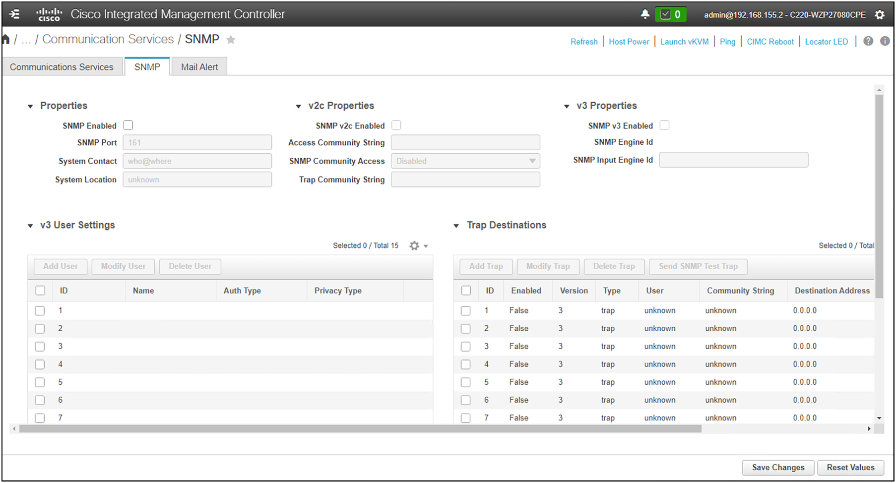
SNMP configuration
Cisco MIBs and instructions are available at the following:
GitHub - cisco/cisco-mibs: Various SNMP MIBs from Cisco
Table 5. Important OIDs (object identifiers)
| Trap |
Description |
| cucsFaultActiveNotif The OID for this SNMP trap is |
This notification is generated by a Cisco UCS instance whenever a fault is raised. |
| cucsFaultClear otif The OID for this SNMP trap is |
This notification is generated by a Cisco UCS instance whenever a fault is cleared. |
Table 6. Fault attributes (variable bindings).
| Attribute |
Description |
| Fault Instance ID (Table Index) |
A unique integer that identifies the fault |
| Affected Object DN |
The distinguished name of the mutable object that has the fault. |
| Affected Object OID |
The Object Identifier (OID) of the mutable object that has the fault. |
| Creation Time |
The time that the fault was created. |
| Last Modification |
The time when any of the attributes were modified. |
| Code |
A code that provides information specific to the nature of the fault. |
| Type |
The fault type. |
| Cause |
The probable cause of the fault. |
| Severity |
The severity of the fault. |
| Occurrence |
The number of times that a fault has occurred since it was created. |
| Description |
A human readable string that contains all information related to the fault. |
Mail alerts
Mail alerts are a convenient way to stay immediately up to date on system events. Enabling these alerts provides the following benefits:
● Allows you to choose the minimum severity level for receiving email alerts
● Supports email-based notification of server faults using Simple Mail Transfer Protocol (SMTP)
● Can send alerts for different severity levels (condition, warning, minor, major, critical)
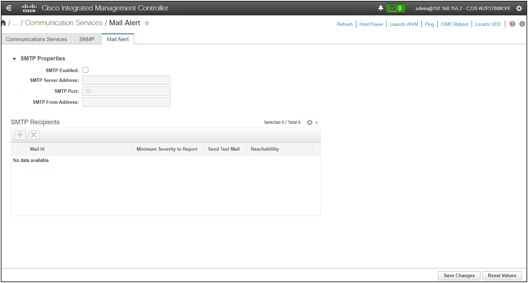
Configuring mail alerts through SMTP
System events and audit records
To gain an understanding of existing, emerging, and historic events that are related to security incidents, an organization should have a unified strategy for event logging and correlation. This strategy must leverage logging from all network devices and use prepackaged and customizable correlation capabilities. Cisco UCS has a syslog capability that allows aggregation of logs at a centralized log server.
After centralized logging is implemented, a structured approach must be developed to analyze logs and track incidents. Based on the needs of the organization, this approach can range from a simple diligent review of log data to an advanced rule-based analysis.
The Cisco UCS audit log has a maximum of 10,000 entries. It utilizes a circular, FIFO-logging design, so the oldest entries will drop off as new entries are created. If you are at the 10,000-entry limit, you can rotate the logs on your centralized server, or you can export the log file as .csv from the GUI, or you can, for example, issue commands through PowerShell to also pull the logs.
For the sake of consolidation and to make forensic analysis easier, it is recommended to configure a remote syslog server for your system(s). This provides a single point of log aggregation to make data mining and event tracking simpler. When you configure remote syslog, be sure to select the “secure” checkbox to ensure that your log pushes are encrypted.
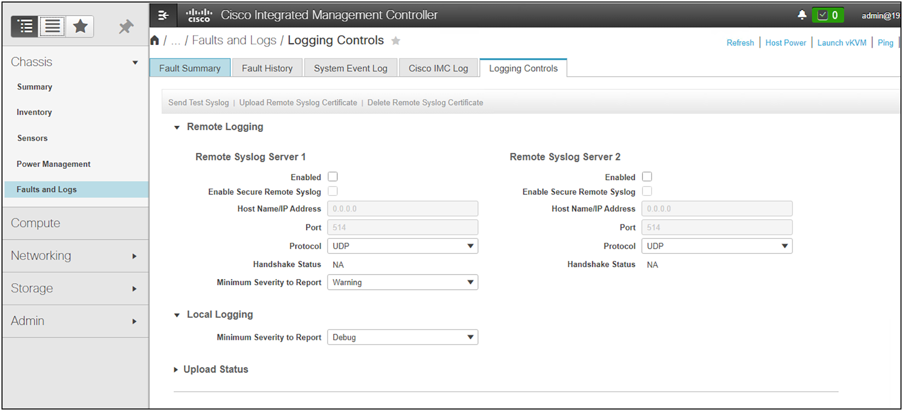
Setting up remote logging
Figure 29 shows the CIMC Log, which displays an audit record of system interaction and user activity. Various filters can be applied to the entry list to help narrow down items of interest.
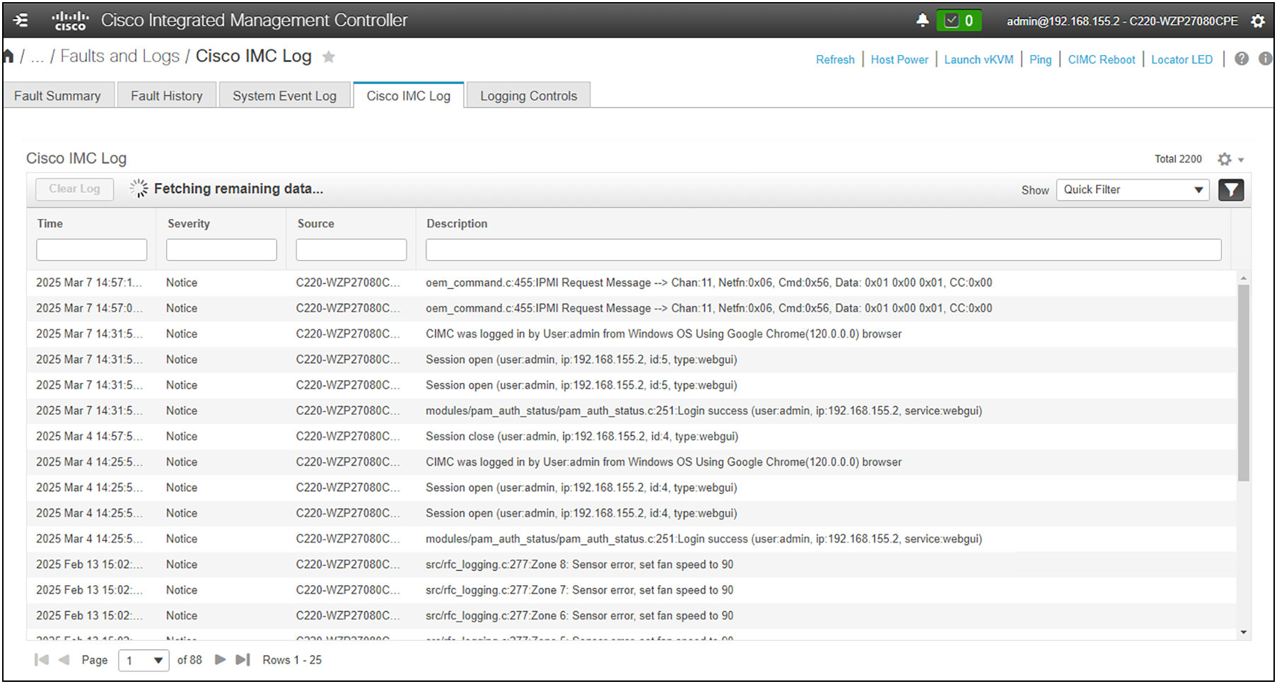
Audit records in the CIMC log
The figure below shows a typical system event log. The event log displays system faults of various severity. See the faults section in this paper for a description of the various types of logged incidents.
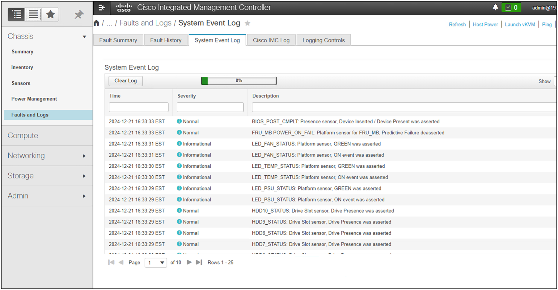
System event logging
Next, we will examine in the secure Cisco UCS posture for application operation. It is crucial that the system be able to ensure that applications can run in a fenced and protected compute regime. To this end, confidential computing is used, in hardware, to ensure isolated, encrypted, and protected execution.
Confidential computing
Confidential computing is a cloud-computing technology that isolates sensitive data in a protected CPU enclave during processing. The contents of the enclave—the data being processed and the techniques used to process it—are accessible only to authorized programming code and are invisible and unknowable to anything or anyone else, including the cloud provider.
A confidential computing secure enclave refers to a protected and isolated environment within a computing system where sensitive data or operations can be securely processed or stored. This secure enclave ensures that the data within it is protected from unauthorized access, even from other parts of the system or privileged software layers.
The concept of secure enclaves is primarily focused on maintaining the confidentiality, integrity, and privacy of sensitive information, especially when dealing with critical data or executing sensitive operations. These enclaves use hardware-based security mechanisms to create isolated and trusted spaces within the system's memory or processing units, offering a high level of protection against various types of attacks, including those attempting to access or manipulate the enclave's contents.
As company leaders rely more and more on public- and hybrid-cloud services, data privacy in the cloud is imperative. The primary goal of confidential computing is to provide greater assurance to leaders that their data in the cloud is protected and confidential, and to encourage them to move more of their sensitive data and computing workloads to public-cloud services.
For years, cloud providers have offered encryption services to help protect data at rest (in storage and databases) and data in transit (moving over a network connection). Confidential computing eliminates the remaining data-security vulnerability by protecting data in use — that is, during processing or runtime.
How confidential computing works
Applications process data, and to do this, they interface with a computer’s memory. Before an application can process (encrypted) data, it has to go through decryption in memory. Because the data is, for a moment, unencrypted, it is left exposed. It can be accessed, encryption-free, right before, during, and right after it has been processed. This leaves it exposed to such threats as memory dump attacks, which involve capturing and using Random Access Memory (RAM) put on a storage drive in the event of an unrecoverable error.
The attacker triggers this error as part of the attack, forcing the data to be exposed. Data is also exposed to root user compromises, which occur when the wrong person gains access to admin privileges and can therefore access data before, during, and after it has been processed.
Confidential computing fixes this issue by using a hardware-based architecture referred to as a Trusted Execution Environment (TEE). This is a secure coprocessor inside a CPU. Embedded encryption keys are used to secure the TEE. To make sure the TEEs are only accessible to the application code authorized for it, the coprocessor uses attestation mechanisms that are embedded within the application. If the system comes under attack by malware or unauthorized code as it tries to access the encryption keys, the TEE will deny the attempt at access and cancel the computation.
This allows sensitive data to stay protected while in memory. When the application tells the TEE to decrypt it, the data is released for processing. While the data is decrypted and being processed by the computer, it is invisible to everything and everyone else. This includes the cloud provider, other computer resources, hypervisors, virtual machines, and even the operating system.
Intel and AMD offer different technologies and approaches to achieve confidential computing secure enclaves within their respective processor architectures. Below is a comparison between Intel's technologies (SGX, TDX, and TME) and AMD's features (SEV and SME) in terms of their approaches, functionalities, and key characteristics.
Intel's technologies
Intel SGX (Software Guard Extensions) creates isolated secure enclaves within the CPU's memory, allowing applications to protect sensitive code and data. This enables developers to create isolated execution environments for applications, protecting data and code even from higher-privileged software layers. It provides memory encryption, secure execution, remote attestation, and isolation.
Intel TDX (Total Memory Encryption and Intel Trusted Execution Technology [Intel TXT]) focuses on enhancing security in virtualized environments by providing memory encryption and secure execution environments for virtual machines. It provides total memory encryption, secure boot processes, and hardware-based isolation to protect against attacks in virtualized environments. TDX protects VMs from unauthorized access and tampering, ensures secure migrations, and provides a trusted execution environment.
Intel TME (Total Memory Encryption) encrypts system memory to safeguard against unauthorized access, ensuring data confidentiality even if an attacker gains physical access to the memory. It protects system memory contents through encryption, ensuring data confidentiality and integrity. Intel TME aims to prevent data breaches and unauthorized access to memory contents.
AMD's technologies
AMD SEV (Secure Encrypted Virtualization) focuses on enhancing security in virtualized environments by providing hardware-based memory encryption for VMs. It offers memory encryption for each VM, isolating them from each other and the hypervisor, protecting against attacks in cloud environments. AMD SEV provides memory encryption, isolation, and facilitates secure VM migrations between physical hosts.
AMD SME (Secure Memory Encryption) encrypts the system's memory, protecting against unauthorized access and physical attacks by encrypting memory contents. It encrypts system memory contents transparently without requiring specific software modifications, protecting against memory snooping attacks. AMD SME protects memory contents through encryption, enhancing security against physical attacks.
Comparing the two, both Intel and AMD technologies aim to provide hardware-based security mechanisms to protect sensitive data and create secure enclaves. Intel SGX and AMD SEV focus on creating isolated execution environments for applications or virtual machines, whereas Intel TME and AMD SME concentrate on encrypting system memory to protect against unauthorized access.
Intel TDX is tailored more for virtualized environments, offering features for VM security, while AMD SEV is similarly focused on enhancing security in virtualized environments. Each technology has its unique characteristics, such as Intel SGX's focus on secure execution or AMD SEV's capabilities for secure VM migrations.
Overall, both Intel and AMD technologies contribute significantly to confidential computing by offering hardware-based security features, encryption mechanisms, and isolation to protect against various threats and attacks targeting sensitive data and applications. The choice between these technologies often depends on specific use cases, system requirements, and compatibility with the existing infrastructure.
Why use confidential computing?
In summary, confidential computing is critically important in server operations for the following reasons:
● To protect sensitive data, even while in use — and to extend the benefits of cloud computing to sensitive workloads. When used together with data encryption at rest and in transit with exclusive control of keys, confidential computing eliminates the single largest barrier to moving sensitive or highly regulated data sets and application workloads from an inflexible, expensive on-premises IT infrastructure to a more flexible and modern public-cloud platform.
● To protect intellectual property. Confidential computing isn't just for data protection. The TEE can also be used to protect proprietary business logic, analytics functions, machine learning algorithms, or entire applications.
● To collaborate securely with partners on new cloud solutions. For example, one company's team can combine its sensitive data with another company's proprietary calculations to create new solutions - without either company sharing any data or intellectual property that it doesn't want to share.
● To eliminate concerns when choosing cloud providers. Confidential computing lets a company leader choose the cloud-computing services that best meet the organization's technical and business requirements, without worrying about storing and processing customer data, proprietary technology, and other sensitive assets. This approach also helps alleviate any additional competitive concerns if the cloud provider also provides competing business services.
● To protect data processed at the edge. Edge computing is a distributed computing framework that brings enterprise applications closer to data sources such as IoT devices or local edge servers. When this framework is used as part of distributed cloud patterns, the data and application at edge nodes can be protected with confidential computing.
Confidential Computing Consortium
In 2019, a group of CPU manufacturers, cloud providers and software companies — Alibaba, AMD, Baidu, Fortanix, Google, IBM/Red Hat, Intel, Microsoft, Oracle, Swisscom, Tencent, and VMware — formed the Confidential Computing Consortium (CCC) under the auspices of The Linux Foundation. Cisco is a member of the consortium.
The CCC's goals are to define industry-wide standards for confidential computing and to promote the development of open-source confidential computing tools. Two of the Consortium's first open-source projects, Open Enclave SDK and Red Hat Enarx, help developers build applications that run without modification across TEE platforms.
However, some of today's most widely used confidential computing technologies were introduced by member companies before the formation of the Consortium. For example, Intel SGX (Software Guard Extensions) technology, which enables TEEs on the Intel Xeon® CPU platform, has been available since 2016; in 2018 IBM made confidential computing capabilities generally available with its IBM Cloud Hyper Protect Virtual Servers and IBM Cloud Data Shield products.
Secure data delivery and storage
The third and final pillar we will examine is the secure storage and delivery of data. This deals with encryption, key management, and data ingress/egress isolation. Traditional ciphers used in data encryption are nearing their functional end-of-life due to the encroaching capabilities of quantum computing. It is becoming increasingly important to consider and utilize post-quantum cryptography as part of a holistic approach securing data. To this end, Cisco announced membership in the Post-Quantum Cryptography Alliance in February of 2024. The goal is to guide and implement quantum-resistant ciphers in the industry and across Cisco products.
Encryption and key management
Encryption and remote key management play critical roles in ensuring secure data delivery, particularly in scenarios where sensitive information is transmitted or stored. These security measures contribute to protecting data confidentiality, integrity, and authenticity.
Encryption is primarily employed to ensure the confidentiality of data during transmission or while stored on a system. Cisco UCS supports hardware-based encrypted drives (SEDs) and can maintain a local key or be configured to securely use a remote Key Management Server (KMS). This is encryption for data at rest (DARE). Data in transit can be encrypted in many ways and Cisco UCS has a robust ecosystem to take advantage of on-wire encryption solutions based on Cisco products. This can be accomplished in hardware (for example, on point-to-point or perimeter network devices) or by using “Cisco on Cisco” with the myriad virtual solutions that can run directly in a containerized Cisco UCS or hypervisor-based deployment. By encrypting data at both ends—during transmission and storage—organizations ensure that sensitive information remains secure throughout its lifecycle.
Key management is an important aspect of an encryption deployment. Remote key management involves securely storing encryption keys separately from the encrypted data. Keys are often considered to be as sensitive as the data they encrypt. By managing keys remotely and securely, organizations prevent a single point of failure and reduce the risk of unauthorized access to both data and keys.
Regularly rotating and updating encryption keys is a security best practice. Remote key management systems facilitate the secure rotation and distribution of new keys. This helps ensure that even if a key is compromised, the window of vulnerability is limited, and older keys are no longer in use.
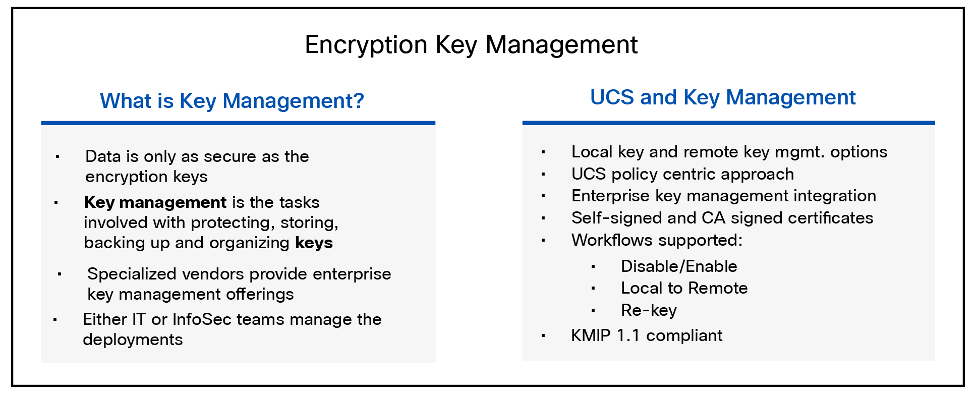
Cisco UCS key management features
Self-Encrypting Drives (SEDs)
Data-at-rest encryption on a Cisco UCS server can happen in software for VMs (for example, using VMcrypt) or by the operating system (for example, Microsoft BitLocker). This can also be accomplished using hardware. To that end, self-encrypting drives (SEDs) were developed and have many advantages. SEDs have a negligible impact on performance speed and latency. The encryption process is completely integrated into the drive, so there is no need for other system components to step in and perform any heavy lifting. SEDs are independent of the operating system, so even if a hacker attacks a computer, it is nearly impossible to access the SED (and the encryption keys stored within) when the computer is turned off.
In a Cisco UCS server, SEDs can utilize a local key (security key) or a remote key management solution. Remote key management is the recommended method since it doesn’t rely on stored or “remembered” pass phrases. The key management software optimizes the SED’s decryption and encryption functions, and key management, relieving the user of any active SED administration. Lastly, SEDs are inexpensive to deploy and maintain. SEDs encrypt the moment they come off the assembly line. Management software does the rest, ensuring that SEDs do their job without the need for human intervention.
Self-Encrypting Drives (SEDs) have special hardware that encrypts incoming data and decrypts outgoing data in real-time. The data on the disk is always encrypted in the disk and stored in the encrypted form. The encrypted data is always decrypted on the way out of the disk. A media encryption key controls this encryption and decryption. This key is never stored in the processor or memory. Cisco UCS Manager supports SED security policies on Cisco UCS C-Series servers, B-Series M5 servers, and S-Series servers.
SEDs must be locked by providing a security key. The security key, which is also known as a key-encryption key or an authentication passphrase, is used to encrypt the media encryption key. If the disk is not locked, no key is required to fetch the data.
Cisco UCS Manager enables you to configure security keys locally or remotely. When you configure the key locally, you must remember the key. If you forget the key, it cannot be retrieved, and the data is lost. You can configure the key remotely by using a key management server (also known as KMIP server). This method addresses the issues related to safe-keeping and retrieval of the keys in the local management.
The encryption and decryption for SEDs is done through the hardware. Thus, it does not affect the overall system performance. SEDs reduce the disk retirement and redeployment costs through instantaneous cryptographic erasure. Cryptographic erasure is done by changing the media encryption key. When the media encryption key of a disk is changed, the data on the disk cannot be decrypted, and is immediately rendered unusable. With Cisco UCS Manager Release 3.1(3), SEDs offer disk-theft protection for C-Series and S-Series servers.
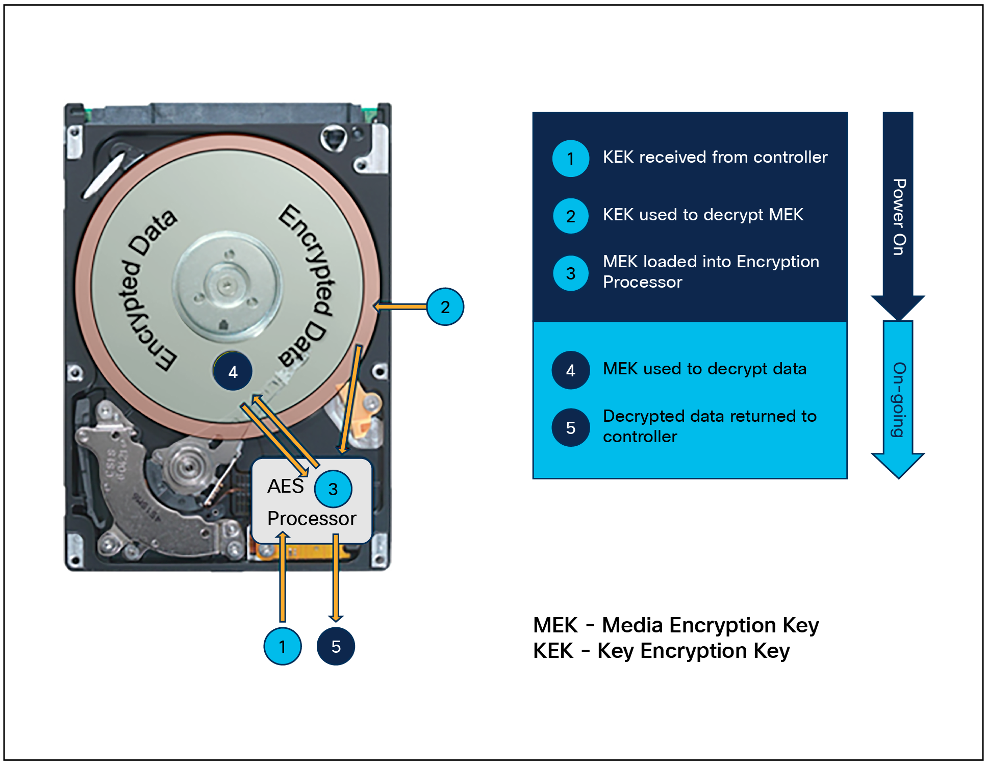
Anatomy of a self-encrypting drive
Instant secure erase drives
Drive Secure Erase is a function used to permanently delete data from storage devices such as Solid State Drives (SSDs) and Hard Disk Drives (HDDs). It overwrites the data on the drive with random new data, making it impossible to recover the original content by using data recovery software methods. Instant Secure Erase (ISE) is a superset of non-crypto-based secure-erase commands; it utilizes encryption to make data unreadable. ISE contains secure-erase commands but also adds a "crypto" erase command. This command can be utilized by both hard disks and solid-state drives if available. With ISE, each disk creates a cipher key that is used to decrypt/encrypt data as it is being read or written. When the crypto command is accessed, the cipher key is destroyed and all data on the disk is unable to be read. Because there is no need to overwrite the data, ISE only takes a few milliseconds to make the disk unreadable compared to other sanitization methods, which can take several hours, depending on the number of passes and the size of the disk. Instant secure erase is also supported by NIST (under cryptographic erase) and is usually coupled with FIPS (Federal Information Processing Standard) certification.
While instant secure erase uses cryptographic techniques to securely erase data, it does not offer data encryption to protect data at rest. SEDs are required for this (see the previous section).
Decommissioning
Securely decommissioning a server is a critical process to ensure that sensitive data is properly handled, and the server is retired in a way that minimizes the risk of data breaches or unauthorized access. Failing to decommission a server securely can lead to data exposure, legal and regulatory issues, and potential harm to an organization's reputation. This section discusses the importance and methods for securely decommissioning a server and its data.
Decommissioning a system or components of a system, specifically drives, requires special consideration in many circumstances. It is not sufficient to simply remove a drive or rotate a system out of production without sanitization. There are third-party applications that will run NIST-approved sanitization routines on plain text drives or encrypted drives. The Commission Regulation (EU) 2019/424 requires that data be securely disposed of. Secure data disposal is accomplished by using commonly available tools that erase the data from the various/drives, memory, and storage in the Cisco UCS servers and reset them to factory settings. You must be familiar with what devices are present in your Cisco UCS server and run the appropriate tools for secure data deletion. In some cases, you may need to run multiple tools.
Proper decommissioning reduces the risk of data breaches. If data is not securely wiped, deleted, or destroyed, it may be accessible to unauthorized individuals who can exploit it for malicious purposes.
Secure decommissioning is essential for compliance with data protection and privacy regulations. Many regulations, such as GDPR or HIPAA, require organizations to safeguard data, even during disposal. It also serves to protect an organization’s intellectual property.
Additional procedural steps can be taken as well. These include physical destruction and environmentally responsible recycling of components where appropriate. If this is not possible because the systems will be reused, other things can be done such as disabling and removing all user accounts and resetting server configurations.
Secure decommissioning is a comprehensive process that involves technical, procedural, and organizational measures. By following these methods, organizations can minimize the risks associated with retiring servers and ensure that sensitive data is handled responsibly and securely.
Data sanitization in UCSM, CIMC, and IMM
Beginning with release 4.2(3d), CIMC supports a data sanitization feature. Using the data sanitization process, CIMC erases all sensitive data, thus making extraction or recovery of customer data impossible. As CIMC progresses through the erasure process, the status report is updated. You can check the status and progress of the data sanitization process for each individual device-erasure from the report and identify and rectify any issues, if required.
The erasure process for data sanitization is performed in the following order on the server components:
1. Storage
2. VIC
3. BIOS
4. CIMC
You can choose to either perform data sanitization on all the server components or select only VIC and storage components for data sanitization.
CIMC reboots when data sanitization is completed and generates a report.
See the first version release notes here: https://www.cisco.com/c/en/us/td/docs/unified_computing/ucs/release/notes/b_release-notes-for-cisco-ucs-rack-server-software-release-4_2_3.html
This is also referenced in the “Decommissioning” section of the Cisco Compute Security Overview White Paper: Cisco Compute Security Overview White Paper - Cisco
Note that this process is NIST 800-88 compliant. Also note that it is only applicable to drives that support the built-in tools.
We can ensure that our server environments are as secure as possible when we combine the inherent security features of the platform described in this document with such common-sense security practices as the following:
● Maintain physical security
● Keep server OS and firmware patched and updated to mitigate new threats
● Disable functions that are not required
● Maintain application security with RBAC, patching, and firewalls
● Store and deliver the data securely with encryption in hardware on the server and on the wire through ecosystem design
For additional information, see the following resources:
Cisco Trustworthy Technologies
Audit log entries and retention
Cisco UCS Secure Data Deletion
Post-Quantum Cryptography Alliance
Multifactor Authentication with UCSM
Additional Cisco monitoring resources (cited in this document):
● Cisco UCS standalone C-Series MIB reference guide
● Cisco UCS C-Series servers fault reference guide
● Monitoring Cisco UCS Manager with Syslog
● Cisco UCS Manager and C-Series’ Tech Talk available here
The tables below list the incoming and outgoing TCP and UDP ports used in Cisco UCS for management access.
Table 7. Incoming ports
| Port |
Interface |
Protocol |
Traffic type |
Usage |
| 23 |
CLI |
Telnet |
TCP |
CIMC CLI access |
| 22 |
CLI |
SSH |
TCP |
CIMC CLI access |
| 443 |
Static HTML |
HTTPS |
TCP |
CIMC UI Access |
| 80 |
Static HTML |
HTTP |
TCP |
Client download |
| 23 |
Serial-over-LAN |
Telnet |
TCP |
COM1 port access on a specified server |
| 22 |
Serial-over-LAN |
SSH |
TCP |
COM1 port access on a specified server |
| 161 |
SNMP |
SNMP |
UDP |
SNMP MIBs exposed for monitoring |
| 623 |
IPMI-over-LAN |
RMCP |
UDP |
IPMI access to BMCs |
| 2068 |
KVM |
HTTPS |
TCP |
Data path for the BMCs |
| 5988 |
CIMC XML |
HTTP |
TCP |
Send CIMC messages over HTTP |
| 743 |
KVM |
HTTP |
TCP |
CIMC web service / direct KVM |
Table 8. Outgoing ports
| Port |
Service |
Protocol |
Traffic type |
Usage |
| 1812 |
AAA |
RADIUS |
UDP |
AAA server authentication requests |
| 1813 |
AAA |
RADIUS |
UDP |
AAA server authentication requests |
| 49 |
AAA |
TACACS |
TCP |
AAA server authentication requests |
| 389 |
AAA |
LDAP |
UDP |
AAA LDAP server authentication requests |
| 123 |
Time sync |
NTP |
UDP |
Synchronize the time with global time servers |
| 162 |
SNMP traps |
SNMP |
UDP |
Send traps to a remote network management system |
| 25 |
Call home |
SMTP |
TCP |
Email-based and web-based notifications for critical system events |
| 514 |
Syslog |
SYSLOG |
UDP |
Syslog messages generated by Cisco UCS |
| 53 |
Name resolution |
DNS |
UDP |
DNS queries |
| 69 |
TFTP |
TFTP |
UDP |
File transfers |
| 115 |
SFTP |
SFTP |
TCP |
File transfers |
| 20-21 |
FTP |
FTP |
TCP |
File transfers |
| 21 |
SCP |
SCP |
TCP |
File transfers |
Appendix B – Post quantum cryptography terms
AIK – Attestation Identity Key. The Trusted Platform Module (TPM) can be used to create cryptographic public/private key pairs in such a way that the private key can never be revealed or used outside the TPM (that is, the key is non-migratable). This type of key can be used to guarantee that a certain cryptographic operation occurred in the TPM of a particular computer by virtue of the fact that any operation that uses the private key of such a key pair must occur inside that specific TPM.
It can also be useful to be able to cryptographically prove such a property of a key, so that proof of any use of the private key must have occurred inside that TPM.
An Attestation Identity Key is used to provide such a cryptographic proof by signing the properties of the non-migratable key and providing the properties and signature to the CA for verification. Since the signature is created using the AIK private key, which can only be used in the TPM that created it, the CA can trust that the attested key is truly non-migratable and cannot be used outside that TPM.
CA – Certificate Authority, a trusted certificate signature provider.
CC – Common Criteria is an international standard for computer security certification. It has various evaluation levels called EALs. Most organizations typically certify to EAL 2.
Cisco SKS – Cisco Session Key Services, basically proprietary SKIP
CNSA – Commercial National Security Algorithm (Suite) is a set of cryptographic algorithms promoted by the National Security Agency as a replacement for NSA Suite B Cryptography algorithms.
CSfC - Commercial Solution for Classified certifications
DH – Diffie Hellman key exchange algorithm.
EAP-TLS - Extensible Authentication Protocol–Transport Layer Security (EAP-TLS) is an IETF open standard defined in RFC 5216. More colloquially, EAP-TLS is the authentication protocol most commonly deployed on WPA2-Enterprise networks to enable the use of X.509 digital certificates for authentication.
EAP-TLS is considered the gold standard for network authentication security, but despite being universally recognized as ultra-secure, it’s still not widely implemented.
ECC - Elliptic-curve cryptography is an approach to public-key cryptography based on the algebraic structure of elliptic curves.
ECDH - Elliptic-curve Diffie–Hellman is a key agreement protocol that allows two parties, each having an elliptic-curve public–private key pair, to establish a shared secret over an insecure channel.
HSS - Hierarchical Signature System.
IETF - Internet Engineering Task Force, founded in 1986, is the premier Standards Development Organization (SDO) for the Internet.
IKE - IKE (Internet Key Exchange) is a protocol used in IPsec (Internet Protocol Security) for ensuring secure, authenticated key exchange and establishing Security Associations (SAs). IKE plays a crucial role in setting up the cryptographic parameters for securing IP communications.
IKE automates the process of generating, exchanging, and managing cryptographic keys required for IPsec, and also negotiates the IPsec Security Associations (SAs) parameters.
Kyber - a Key Encapsulation Mechanism (KEM) designed to be resistant to quantum decryption attacks. It is used to establish a shared secret between two communicating parties without an attacker in the transmission system being able to decrypt it. This is an asymmetric cryptosystem.
LDWM – Lamport, Diffie, Winternitz, and Merkle – a special hashing scheme developed for signatures that is considered quantum resistant.
LMS - Leighton-Micali Signature, a stateful hash-based algorithm and its multi-tree variants used for HSS.
MACSEC – MAC address security. MACsec typically relies on PPK.
NDcPP - Network Device Collaborative Protection Profile
OTN SEC – Optical Transport Network security
QKD - Quantum key distribution is a secure communication method that implements a cryptographic protocol involving components of quantum mechanics. It enables two parties to produce a shared random secret key known only to them, which then can be used to encrypt and decrypt messages. The process of quantum key distribution is not to be confused with quantum cryptography, as it is the best-known example of a quantum-cryptographic task.
PPK – Pre-placed Key (symmetric encryption key, pre-positioned in a cryptographic unit).
PQC – Post Quantum Cryptography
SHA – Secure Hash Algorithm
Shim – the shim is the pre-bootloader that runs on UEFI systems, meant to be a bit of code signed by Microsoft, that embeds our (Cisco’s) own certificate (which signs our grub binaries), so that it can load the "real" bootloader: GRUB.
SKIP - SKIP (Simple Key-Management for Internet Protocol) is a protocol for sharing encryption keys. It generates platform-independent encryption keys for specific sender-receiver pairs. The skip cipher is a transposition cipher that reorders letters in a message. In SKIP, the master key is hashed to produce the key used for IP packet-based encryption and authentication.
SUDI - Secure Unique Device Identifier is an IEEE 802.1AR-compliant secure device identity in an X.509v3 certificate which maintains the product identifier and serial number. The SUDI can be used for asymmetric key operations such as encryption, decryption, signing, and verifying that allow passage of the data to be operated upon.
TPM – Trusted Platform Module. An immutable hardware key store.
XMSS - eXtended Merkle Signature Scheme, a stateful hash-based algorithm and its multi-tree variants used for HSS.
Appendix C – USB OS install boot procedure
Media requirements
Because UEFI is more restrictive than legacy BIOS, there are specific requirements for your USB drive and BIOS settings to ensure that the drive is recognized. In a hardened posture, the USB ports should be disabled. This procedure shows you how to enable them for OS installation. Be sure to disable them again once the OS install is complete. Note that you may need to add Cisco drivers downloaded from CCO to the boot image to complete the OS installation (for example, mass storage drivers).
USB drive requirements for UEFI
For the BIOS to "see" the USB drive as a UEFI bootable device:
● File system: The USB drive must be formatted as FAT32. UEFI firmware typically cannot read NTFS or exFAT partitions for booting.
● Partition scheme: It is recommended to use GPT (GUID Partition Table) rather than MBR.
● Boot files: The drive must contain the \EFI\BOOT\BOOTX64.EFI file (this is standard for most modern OS installers, such as Windows Server, RHEL, or VMware).
USB enablement requirements
1. Enabling physical USB Ports (BIOS)
a. If the USB ports were disabled for security reasons, you must re-enable them in the BIOS.
2. Restart the server and press F2 when the Cisco logo appears to enter the BIOS Setup.
3. Navigate to the Advanced tab.
4. Select USB Configuration.
5. Ensure USB Stack is set to [Enabled].
6. Check USB Port Configuration to ensure individual ports (Front, Rear, Internal) are set to [Enabled].
7. Press F10 to save and exit.
Important Note: Smart Access USB must be set to “Host” mode.
On M7 servers, the front-panel USB port can be toggled between the Host OS and the BMC (CIMC).
If your USB drive is not being detected by the BIOS, ensure that Smart Access USB is set to "Host" mode in the CIMC settings or BIOS. You can check this in CIMC under Compute > BIOS > Advanced > USB Configuration.
Procedure requirements
To boot from a USB drive for OS installation on a Cisco UCS C220 M7 Rack Server, you can use either a physical USB drive or the "Virtual Media" feature through the Cisco Integrated Management Controller (CIMC).
Method 1: Using a physical USB drive (one-time boot)
This is the fastest method if you have a physical bootable USB drive plugged into the server.
1. Insert the USB drive into one of the USB ports (front or rear).
2. Power on or restart the server.
3. Watch the screen during the POST (power-on self-test) process. When the Cisco splash screen appears, press F6 to enter the Boot Menu.
4. A list of bootable devices will appear. Select your USB drive (it may appear as "USB Device," "Generic Flash Disk," or by the manufacturer's name).
5. Press Enter to begin the installation.
Method 2: Using CIMC Virtual Media (recommended)
This method allows you to "mount" an ISO file from your laptop or workstation as if it were a physical USB/DVD drive.
1. Log in to the CIMC Web UI using the server's management IP.
2. Launch the KVM Console (click the "Launch KVM" button).
3. In the KVM window, click on the Virtual Media tab and select Activate Virtual Devices.
4. Click Map CD/DVD (or Map Removable Disk) and browse to select your OS ISO file.
5. Once mapped, restart the server from the KVM (Power > Reset System).
6. Press F6 during boot and select Cisco Virtual CD/DVD to boot from the ISO.
Method 3: Changing the permanent boot order (BIOS)
If you want the server to always check the USB port first:
1. Press F2 during boot to enter the BIOS Setup.
2. Navigate to the Boot Options tab.
3. Select Configure Boot Order.
4. Move USB Device or Virtual Media to the top of the list.
5. Press F10 to save and exit.
Appendix D – Trust Anchors and Trusted Platform Modules
Below is a clear, side-by-side explanation of Trust Anchors vs. Trusted Platform Modules (TPMs), what each one does, and how they work together in secure boot, including OS verification. The trust anchor enforces what is allowed to run, while the TPM measures what actually ran and protects secrets based on that measured state. Together they form a complete secure boot and OS verification system.
1. High-level comparison
| Aspect |
Trust Anchor |
TPM (Trusted Platform Module) |
| What it is |
A root of trust (keys + immutable code) |
A secure cryptographic processor |
| Primary role |
Decides what is allowed to run |
Records, protects, and enforces trust decisions |
| Executes code? |
Yes (initial verification code) |
No (policy + crypto only) |
| Can block boot? |
Yes (secure boot enforcement) |
Indirectly, yes (by withholding secrets) |
| Stores secrets? |
Yes (usually public keys) |
Yes (private keys, sealed data) |
| Measures boot state? |
No (by itself) |
Yes (PCRs) |
| Performs attestation? |
No |
Yes |
| Required for secure boot? |
Yes |
No (but strongly recommended) |
2. Trust Anchor: what it does
Definition
A trust anchor is the starting point of trust: something the system assumes is correct and secure.
What it contains
● Immutable verification code (ROM or protected flash)
● One or more public keys
● Policy for verifying firmware
Core responsibilities
● Verifies the next stage before executing it
● Enforces secure boot (allows or denies execution)
● Anchors firmware updates to signed images
Examples of trust anchors
● CPU ROM (hardware root of trust)
● OEM public key embedded in UEFI
● Platform security controller
3. Trusted Platform Module (TPM): what it does
Definition
A TPM is a tamper-resistant cryptographic engine that:
● Measures system state
● Protects secrets
● Enforces security policy based on measurements
Core responsibilities
TPM does not decide what runs—it only reacts to what ran.
● Measures each boot stage (hashing)
● Stores measurements in Platform Configuration Registers (PCRs)
● Seals/unseals secrets based on system state
● Performs attestation (proves system integrity)
4. How they work together during secure boot
Boot flow with both present
[Trust Anchor]
↓ verifies
Firmware
↓ verifies
Bootloader
↓ verifies
OS kernel
Meanwhile:
[TPM]
← measures each step
← records hashes in PCRs
5. Secure boot enforcement (Trust Anchor)
The trust anchor enforces secure boot (this is a prevention mechanism):
● Each stage is digitally signed.
● Signature is verified using trust anchor keys.
● If verification fails:
◦ Execution is blocked.
◦ Recovery mode is entered.
Example:
● UEFI verifies bootloader.
● Bootloader verifies OS kernel.
6. Measured boot and policy enforcement (TPM)
The TPM measures what actually ran (this is a detection + consequence mechanism):
● Each stage’s hash is extended into PCRs.
● PCR values represent the full boot history.
The TPM then:
● Releases secrets only if PCRs match expected values.
● Refuses if firmware or OS was modified.
7. Operating system verification
Trust Anchor side (verification)
● UEFI verifies:
◦ Bootloader signature
◦ Kernel signature
● Ensures that only approved OS code runs
TPM side (measurement and sealing)
● OS boot components are measured.
● Disk encryption keys (for example, BitLocker/LUKS) are sealed to PCRs.
● If OS changes unexpectedly:
◦ TPM will not release keys.
◦ OS cannot access encrypted storage.
8. Why both are needed
Trust Anchor alone
● Prevents unsigned code
◦ Cannot prove system state later
◦ No protection for secrets after boot
TPM alone
● Records system state
◦ Cannot stop malicious code from executing
Together, Trust Anchor and TPM
● Prevent execution of unauthorized code
● Detect tampering
● Protect secrets
● Enable remote attestation
9. Common misconception
“TPM provides secure boot”
● Secure boot is enforced by the Trust Anchor.
● TPM supports secure boot with measurement and policy.
Appendix E – Microchip Adaptec tri-mode disk controller details
Adaptec tri-mode disk controllers are enterprise storage controller cards (HBAs or RAID adapters) made by Microchip Technology under the Adaptec name using Knox-based technologies. Their defining feature is “tri-mode” connectivity, meaning a single controller can manage three different storage interface types simultaneously:
● SAS (serial attached SCSI)
● SATA (serial ATA)
● NVMe (PCIe-based storage)
Traditional controllers supported either:
● SAS/SATA or
● NVMe (PCIe)
Tri-mode controllers unify them by using:
● PCIe lanes for NVMe drives
● SAS protocol for SAS/SATA drives
● A shared physical backplane that can route either protocol
Result: You can plug different drive types into the same system without changing controllers.
Microchip tri-mode (Knox-based) controllers and local/remote key behavior for self-encrypting drives (SED)
Note: If you decide not to cache the SED key on the controller to protect from wandering servers, then any power cycle will be BIOS-interrupted and require a password to access the disks attached to the controller.
Q: Since Knox controllers don’t cache the key encryption key (KEK) by default, if we are in local key (manual key with passphrase) mode, do we need to enter the passphrase on reboot?
A: In LKMS, if the controller password is set, users MUST provide a controller password on reboot in order to let the firmware decrypt the encrypted master key saved in NVRAM to unlock the drive(s).
Q: In local key mode with IMM, is the KEK stored anywhere in Intersight or just generated as needed with the passphrase?
A: KEKs are generated as needed by the controller firmware.
From the Microchip controller documentation:
8.3.4.4 Unlocking Controller
When Controller Password is set in local key management mode, data on the encrypted devices will be offline during system boot. The controller password must be entered to unlock the controller and bring the encrypted devices online. After three wrong attempts, the controller password will be locked out for some time. If controller password is set along with remote key management mode and on any of the subsequent reboot if controller detects that the key management server is unavailable, then unlock option is provided in the UEFI HII menu. Controller can only unlock encrypted devices if the key management server is made available or a valid controller password is entered.
1. Boot to system BIOS setup utility and select the controller to enter the HII configuration utility.
2. From the main menu, select Configure Controller Settings > Self-Encryption Drive (SED) Based Encryption Setup.
3. Select Unlock Controller.
4. Enter controller password, then select Submit.
Note: In local key management mode, it is recommended to supply the password, before performing any operations such as removing or adding the drives. Without the password, the controller will not be able to unlock the drive to perform the RAID operations such as rebuild, background parity initialization, and consistency check operations.
7.2.4.4 SED Keys Management Overview
MCHP controllers do not cache the SED Key (KEK). Instead, the KEK (essentially the SED unlock PIN) is derived by hashing a Master Key, which is:
● Provided by the user in Local KMS (LKMS) mode.
● Provided by a KMS server in External KMS (EKMS) mode.
This KEK is used to unlock each drive's Media Encryption Key (MEK).
● LKMS:
◦ Controller password disabled
◦ Master key is stored in NVRAM as plain text. Master key hashed->generate SED key every time.
◦ Master Key is encrypted and stored in NVRAM. Master key decrypted->hashed->Generate SED key every time when needed.
◦ Controller password enabled.
◦ Controller password is used to encrypt the master key and stored in NVRAM. Master key decrypted->hashed->Generate SED key every time when needed.
● EKMS:
◦ Controller password disabled
◦ Controller gets Master key from KMS server through EFI KMS protocol. Master key hashed -> generate SED key every time. No KMS communication. SED drives remain data locked.
◦ Controller password enabled (controller firmware encrypt the master key from KMS server and stores in NVRAM).
◦ As long as the KMS connection is successful, same above.
◦ If KMS connection is failing, this is where the controller password option is used as a back-up option for user to access data.
◦ The encrypted master key stored in controller NVRAM will be used to unlock all the SEDs as long as user provided a controller password during POST.
RMA scenarios:
Case 1: Server replacement
● Drives and original controller moved to new server with same configuration.
● Controller boots, detects MCHP-owned SEDs, and unlocks automatically.
● If controller password was enabled, it must be entered.
Case 2: Controller replacement
● New controller detects MCHP SEDs, but:
◦ Without encryption: Drives remain locked unless user imports.
◦ With encryption (Master Key B on new controller):
● Volume import prompts user for original Master Key A to unlock SEDs.