Planning and Designing Networks with the Cisco WAE Portfolio White Paper
Available Languages
Bias-Free Language
The documentation set for this product strives to use bias-free language. For the purposes of this documentation set, bias-free is defined as language that does not imply discrimination based on age, disability, gender, racial identity, ethnic identity, sexual orientation, socioeconomic status, and intersectionality. Exceptions may be present in the documentation due to language that is hardcoded in the user interfaces of the product software, language used based on RFP documentation, or language that is used by a referenced third-party product. Learn more about how Cisco is using Inclusive Language.
The Cisco® WAE portfolio, which consists of the WAE Design, WAE Live, and WAE Collector products, delivers the network manageability required for simplifying processes and for delivering cost-efficient, reliable services. Each of these tightly integrated products simultaneously supports planning, engineering, and operational tasks. This paper describes the portfolio and outlines key use cases for planners and designers.
The Cisco WAE portfolio helps enable service providers to achieve and maintain operational excellence by bringing manageability to their networks. This means operating and growing networks efficiently, having the ability to scale operations, and providing services without disruption. These goals are essential to the success of telecommunications providers, whether competing for customers based on cost or based on differentiated services.
Companies differ in their emphasis. For instance, many Internet Service Providers (ISPs) rely mainly on increasing capacity to avoid congestion. In contrast, traditional telecommunication providers often emphasize design and analysis to ensure resiliency, while some service providers consciously forego resiliency and work around congestion operationally.
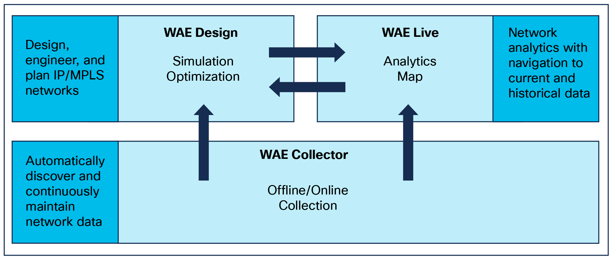
The Cisco WAE portfolio works independently and collectively to meet cross-functional needs (Figure 1). Cisco WAE Live typically (though not exclusively) focuses on the operational scenarios; conversely, the planning and architecture or engineering scenarios typically feature a combination of Cisco WAE Design and WAE Collector.
● Cisco WAE Design is the market-leading integrated system for design, engineering, and planning of IP/MPLS networks
● Cisco WAE Live rapidly delivers in-depth network analytics with efficient navigation to both current and historical data for making critical business and technical decisions
● Cisco WAE Collector automatically gathers and continuously maintains information on infrastructure elements, topology, operational state, and traffic statistics for network planning and analytics
Key Purpose of Each WAE Product
Usage in cross-functional environments
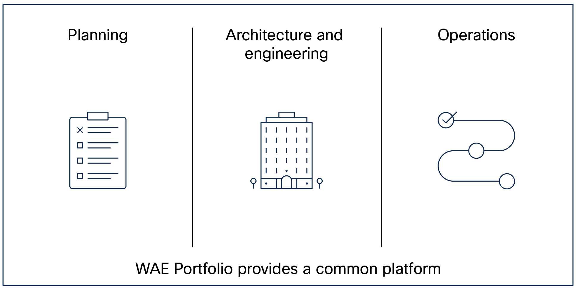
An underlying principle of the WAE portfolio is that many cross-functional activities would be more efficiently performed using a single common platform (Figure 2). The groups that benefit from the WAE portfolio - the planning, design, and operations groups - have complementary goals to ensure that networks remain robust and cost-effective to maintain, and that service agreements are maintained along with profitability.
Not everyone neatly divides responsibilities. Rather, there is often an overlap, with groups having common traffic management goals that are achieved through different means.
● The planning group ensures there is sufficient capacity to avoid congestion and to handle both current and expected traffic growth. Key questions that a planner asks are, “When and where will my network run out of capacity? What will be the impact of adding a new service or customer to my network?”
● The engineering group designs the network and routing to ensure robustness and service delivery, even during failures, in the most economical manner. A typical concern for the architect or engineer is, “Where is my network most vulnerable to failure, and how can I mitigate it?”
● The operations group ensures any congestion is immediately mitigated. Operations staff ask questions such as, “What did the network look like before a failure or congestion? At what rate was bandwidth utilization increasing over the past day, week, month, or year?”
The WAE Portfolio Reaches Across Functional Boundaries
Within planning groups, key areas of concern are growth planning, what-if analysis for topology changes and networks, and testing the impact of new services or customers. Both Cisco WAE Design and WAE Live can be used for this analysis.
Simulating the impact of traffic growth
Network planners must ensure that usage growth is accounted for cost effectively within the risk goals of their company. As such, a planning group often receives or is charged with generating traffic projections based on growth rates so as to determine the right level of build out for accommodating network growth. Predicting growth rates is a difficult, but required facet of success. Scaling network traffic and calculating the network impact is nearly impossible without advanced tools.
Cisco WAE Design helps planners to create growth plans based on measured or simulated traffic. The estimates can be manually entered, for example, based on knowledge of new services being introduced. For simulated traffic (called demands), options exist to group these demands to create aggregations (demand groupings) that meet explicit needs. For instance, planners could aggregate the traffic sourced from a specific site or the traffic destined for a particular autonomous system AS.
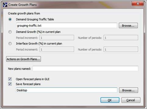
Traffic Scale Based on Demand Groupings
After creating these growth plans, planners can analyze the new plans using the Simulation Analysis tool, and then use the GUI to make further modifications to meet capacity requirements.
Note: Traffic can also be imported into a Cisco WAE Design growth plan tool from a Cisco WAE Live trending report; this can be very useful for determining future needs such as site-to-site traffic trends per class of service.
In Figure 4, WAE Design uses traffic growth projections and runs analysis on both single circuits and Shared-Risk Link Groups (SRLGs) on the network. This allows network planners to determine the effects of worst-case failures, such as where congestion will occur, as well as determine where there is heightened risk of failures. Planners can also analyze the impact of metric changes or circuit additions.
The Return on Investment (ROI) comes from the ability to defer upgrade costs until they are absolutely necessary and to maintain peak staff efficiency.
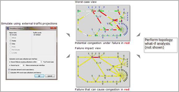
Simulating and Analyzing Worst-Case Failures and Failure Impact
Impact analysis of topology changes or network upgrades
A frequent question in the planning process is how to test the value of a minor change that may obviate the need for a larger one. For instance, rather than a huge upgrade, a planner may consider whether adding a single link between two sites can mitigate congestion over part of the network.
The complete impact of a network upgrade might not be obvious, even to the best engineers, without rigorous evaluation of changing traffic within the network. Ensuring that an upgrade meets requirements without a negative impact is imperative to ensuring that the upgrades are effective uses of capital.
Being able to emulate and predict the impact of these changes promotes Service Level Agreement (SLA) adherence and staff efficiency. Making a topology change could impact traffic flows, congestion, and latency, so knowing the effect such changes would have is valuable for operators, planners, and designers alike, and is critical for those with penalty clauses in customer SLAs.
In the following scenario (Figure 5), the link between Chicago (CHI) and Detroit (DET) is congested, as indicated by the red interface.
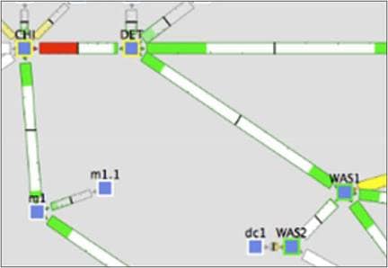
Congestion Between Chicago and Detroit
Using WAE Design (Figure 6), a planner emulates the addition of the new circuit and specifies parameters (such as capacity and metrics) for it.
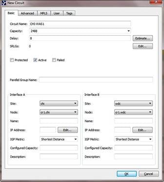
Adding a New Circuit and Its Parameters Is Simple
In this case, viewing the resultant traffic (Figure 7) in this part of the network indicates that the congestion is relieved.
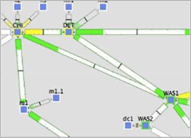
Congestion Relieved as a Result of New Circuit
If congestion had not been relieved, a larger circuit or different metric could have been analyzed with a simple change to the circuit properties in the GUI. As such, Cisco WAE Design allows a rigorous evaluation of the proposed changes without having to perform trial-and-error maintenance in a live network.
Another area in which SLAs can be enforced is with respect to quality of service (QoS). For instance, worst-case analysis can consider QoS parameters, such as interface queue policies, weight, and police limit thresholds.
Impact of a new customer or service
Another role for the planning department is to determine if more capacity is needed to handle new services or customers. In the example shown in Figure 8, the sales department has inquired whether the network can support a new 4-Gbps customer (or service) originating in San Francisco.
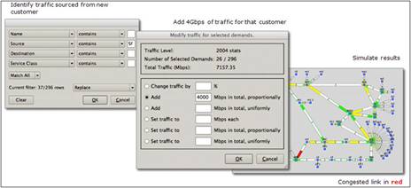
Using WAE Design to Gauge the Impact of a New Customer or Service
WAE Design can be used to reduce the evaluation time to accurately investigate the impact from hours to minutes. First, a planner identifies the traffic for the new customer, and modifies the traffic totals for those demands, and then simulates the results to identify congested links. The planner can also determine whether it is possible to mitigate the congestion by changing metrics or by performing MPLS traffic engineering operations. These exercises help determine if a new circuit is needed.
Similarly, a planner can insert a representative traffic matrix for the new customer or service, and then add new traffic to the network model before simulating the results of these changes (Figure 9).
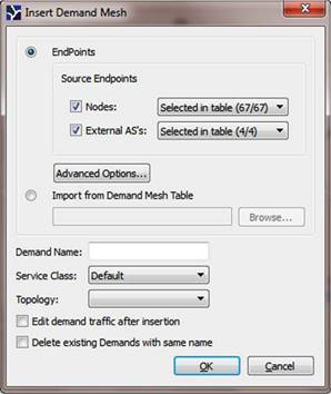
Adding New Demands to the Network Model
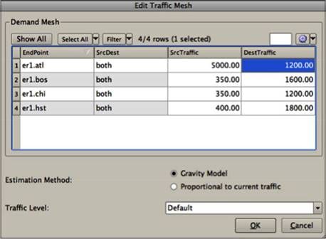
New traffic can then be added to these demands for the simulation. Here, the Cisco-patented Demand Deduction[1] can provide extremely accurate simulations if measured traffic is available. Otherwise, Cisco WAE Design offers both manual and automated methods of simulating demand traffic.
Finally, the simulation is run (Figure 11) to analyze the impact to resiliency and capacity of the network. Since adding new customer demands could impact existing route traffic through congestion, planning methods that use this feature help ensure SLA adherence.
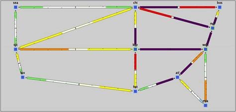
Simulation to Analyze Impact of New Demands
Coordinating peering: planning and operations
Service provider peering[2] is becoming increasingly complex. Peering arrangements between service providers are a necessity on the Internet. They can reduce costs for transit services and increase resiliency and capacity for all parties involved. However, peering relationships must be monitored closely to ensure that they are fair, and commensurate with the original agreement.
Cisco WAE Live allows operators to closely monitor peering on multiple dimensions. In the example given here, there are both planning and operational elements. As shown in Figure 12 a peering interface displaying a disparity (and congestion due to too much traffic coming into the network) can be investigated to view the traffic in both directions. Thus, operators can monitor the high-level health of peering connections across sites, and can quickly navigate to specific interfaces to analyze issues.
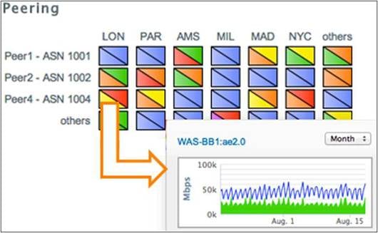
Select a Peering Interface to Immediately Determine Ingress and Egress Traffic
Analytics are immediately available with WAE Live, listing the to/from traffic data. This can enable operators to identify and analyze issues with interfaces and nodes, such as changes to their capacities or routing metrics. For instance (Figure 13), operators can project individual peering interface growth and plan which interfaces will need to be upgraded and when.
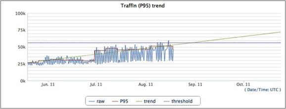
Trends for Incoming Traffic on a Peering Interface
This planning is further augmented by the ability to report periodically (Figure 14) on aggregated traffic coming in and out of peering interfaces. These results can be used as the basis for ongoing peering negotiations.
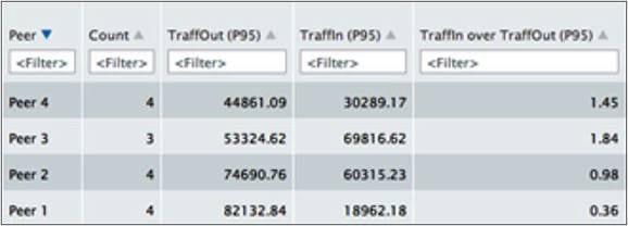
Report on Total Traffic at Peering Locations
Architecture and engineering usage scenarios
The engineering group needs to ensure that the network is robust and that service delivery can be assured - even during failures - in the most economical manner possible. There are several techniques used by this group; a key one is to load balance traffic.
Balancing traffic using MPLS traffic engineering
Load balancing allows for careful management of traffic levels to ensure protection in the event of failure. In some circumstances it can be used to offload traffic from expensive or poorly protected routes onto cheaper or more robust ones. Savings come from being able to delay investment in additional bandwidth, and being able to more efficiently use the bandwidth reserved for maintaining service in the event of network failures. Finally, there are savings from staffing efficiencies in calculating routing and bandwidth requirements.
In Figure 15, there are a total of three intercontinental circuits from North America to Europe: one from Boston to London and two from Washington, DC to Amsterdam.
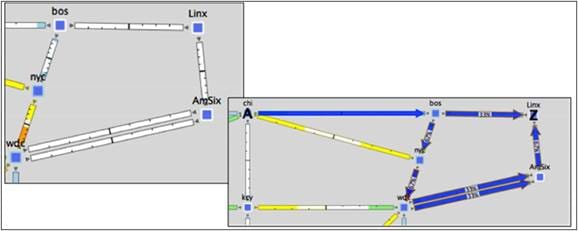
Evaluating Three Intercontinental Circuits (North America to Europe)
An architect might wonder whether there is value in load balancing the MPLS Labeled Switch Paths (LSPs) over these three expensive links, and whether a different placement of LSPs would be more efficient.
In this example, an architect can determine whether all of the affected links run within acceptable fill ranges. It appears that the local and remote terrestrial links would likely take the brunt of traffic impact, but having these links saturated is more cost-effective and less risky than congestion over transoceanic links.
Effectively balancing network traffic over expensive links is often more complex than anything that can be accomplished with Interior Gateway Protocol (IGP) metrics. The operational goal is to increase the utilization of these circuits to the highest possible level, while also maintaining very accurate traffic balancing, even under failure conditions.
The steps below can be used to understand this approach, but this is not the only option to distribute traffic across a set of network links. The recommended steps assume a network with minimal MPLS, but with the ability to construct explicit LSPs with load sharing.
First, architects should identify the set of nodes on each end of the set of costly links. Next, they would build explicit LSPs from each device on each side of the Atlantic to its adjacent node on the other side using all possible transoceanic links. Figure 16 shows three separate paths from Washington DC to Amsterdam. It then shows that LSPs are built between Bos (Boston) and Linx (London Internet Exchange).
Build Explicit LSPs and Place over All Available Paths
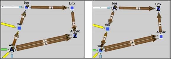
Following this change, an architect can determine whether load sharing is occurring over these LSPs and whether there is an even distribution of traffic over all links. Figure 17 shows load balancing over the northern path.
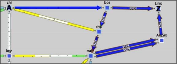
Load Balancing over the Northern Path
By load balancing over both paths and watching the resulting flows, you can analyze the impact to the terrestrial and the transoceanic circuits to ensure that no new capacity issues have been created. Figure 18 shows load balancing over the southern path.
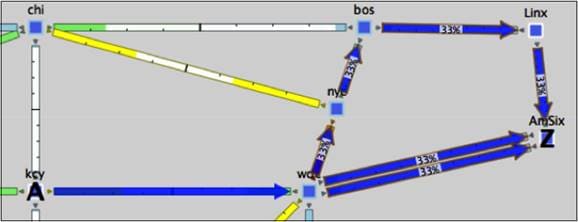
Load Balancing over the Southern Path
Strategic traffic engineering (IGP Metrics)
The engineering group is often faced with the question of whether it is possible to delay a capacity build-out in order to defer capital costs. Often, service level agreements need to be assured with costs kept to a minimum. Figure 19 shows some options you can explore using WAE Design.
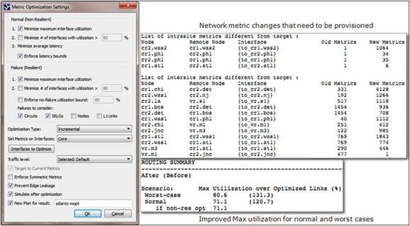
Metric Optimization for Strategic Traffic Engineering
Using the Metric Optimization tool, an engineer selects the option to minimize maximum link utilization while enforcing latency bounds and ensuring availability for circuits and shared risk link groups (SRLGs). WAE Design generates a report of the metric changes that need provisioning to meet these requirements, and shows the maximum utilization that would result for both normal and worst-case failures with these changes. SLAs are assured, and the optimizations result in capital savings.
Building and running a large-scale network requires a series of activities to be performed; these activities are typically divided into planning (months to years), engineering (weeks to months) and operations (tactical on an ongoing basis). These activities are most efficiently performed using a common infrastructure. The Cisco WAE portfolio is the foundational platform to support planning, engineering, and operations.
To learn more about the Cisco WAE portfolio of products visit http://www.cisco.com.
For information about other key features of the WAE Portfolio, contact your representative.