Wi-Fi 7 and the Growing Future of Wireless Design Guide
Available Languages
Bias-Free Language
The documentation set for this product strives to use bias-free language. For the purposes of this documentation set, bias-free is defined as language that does not imply discrimination based on age, disability, gender, racial identity, ethnic identity, sexual orientation, socioeconomic status, and intersectionality. Exceptions may be present in the documentation due to language that is hardcoded in the user interfaces of the product software, language used based on RFP documentation, or language that is used by a referenced third-party product. Learn more about how Cisco is using Inclusive Language.
With the release of Wi-Fi 7, the industry is making steady progress toward being the wireless transport of choice for indoor enterprise coverage. Building on the advancements introduced by Wi-Fi 6 and Wi-Fi 6E, Wi-Fi 7 (802.11be per IEEE) marks a significant upgrade. Wi-Fi 6 Introduced Orthogonal Frequency-Division Multiple Access (OFDMA) and multi-user access, delivering a major leap in airtime efficiency compared to Wi-Fi 5 and earlier OFDM modulation. Wi-Fi 6E expanded on that foundation by adding support for the 6 GHz band—the first spectrum to maintain full backward compatibility with previous Wi-Fi versions—enabling even greater efficiency. Now, Wi-Fi 7 takes these innovations further, unlocking new levels of performance and efficiency.
Much has already been written in blogs and release articles about the “speeds and feeds” of Wi-Fi 7. These performance boosts ultimately mean less waiting and more capacity. But beyond the headline speed increases, Wi-Fi 7 introduces several nuanced enhancements that significantly improve its ability to support the growing diversity and density of today’s smart spaces.
Let’s break down the key advancements—and how they translate into actionable benefits for your environment:
● 4096 Quadrature Amplitude Modulation (QAM): Increases modulation density by 20%
● 320 MHz Channel Width: Doubles the data capacity compared to Wi-Fi 5 and Wi-Fi 6.
● Multi-Link Operation (MLO): Allows clients to use multiple radio bands simultaneously, multiplying airtime opportunities.
● Multiple Resource Unit (MRU): Improves allocation efficiency, minimizing wasted spectrum.
● Preamble Puncturing: Helps avoid interference by selectively ignoring parts of a channel.
● Enhanced Quality-of-Service (QoS): Enables deterministic handling of priority traffic for better performance in latency-sensitive applications.
Higher Data Rates with 4096 QAM
Wi-Fi 7 introduces 4096 QAM, which increases the maximum number of data bits encoded per symbol. Wi-Fi 6’s QAM1024 had 10 bits to Wi-Fi 7’s 12. This translates to a 20% increase in the amount of data that can be sent in a single symbol over the air. In Wi-Fi, both the carrier bandwidth and transmission duration are fixed. One way to transmit more data within this fixed space is by making each data element smaller. That’s exactly what happens with 4096-QAM—more bits are packed into each radio symbol by reducing the size of individual data bits.
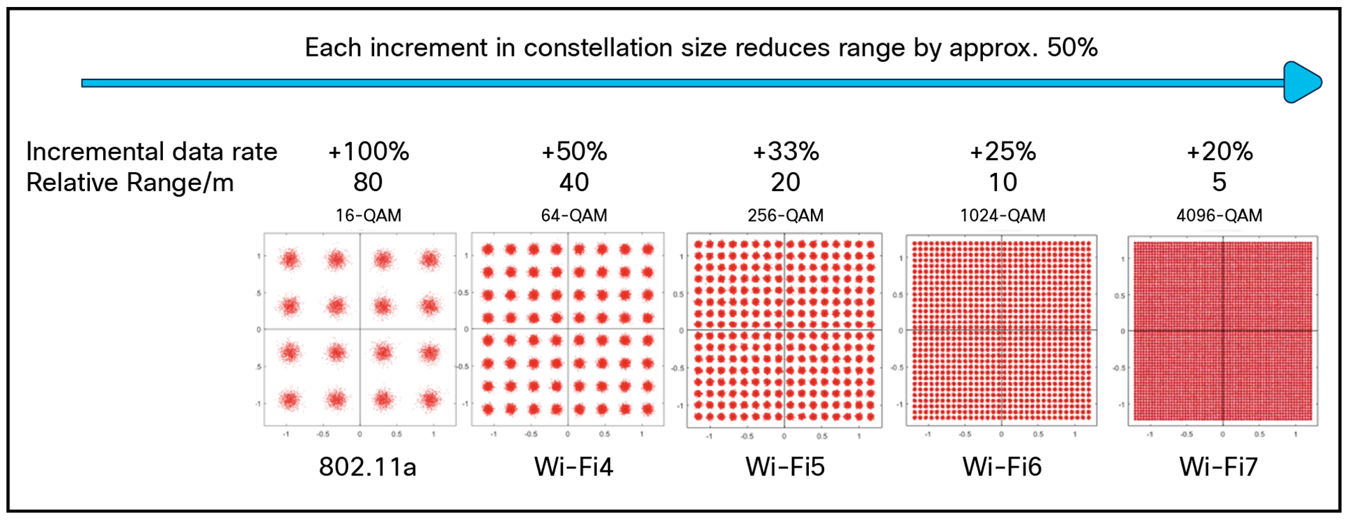
Increasing QAM rates in Wi-Fi specifications
As the data bit density increases within the symbol, differences between individual bits get smaller. The Signal-to-Noise Ratio (SNR) required to accurately demodulate the message goes up as well, to > 43 db. This means that the clients closest to the access point (AP) will benefit the most. The range reduction of Modulation and Coding Scheme (MCS) 12/13 is consistent with QAM density increases in the past. Only another Wi-Fi 7 radio can support MCS 12/13 today. This matters because every client that can get MCS 12/13 connections will get on and off the air 20% faster than every other client in the cell, leaving more airtime for everyone else. That starts paying dividends with the first Wi-Fi 7 client added and stacks up with each additional one.
With Wi-Fi 7, the maximum channel width increases from 160 MHz (in Wi-Fi 5/6) to 320 MHz, effectively doubling potential throughput. This added bandwidth also enables twice as many Resource Units (RUs), allowing for more efficient scheduling and improved overall performance.
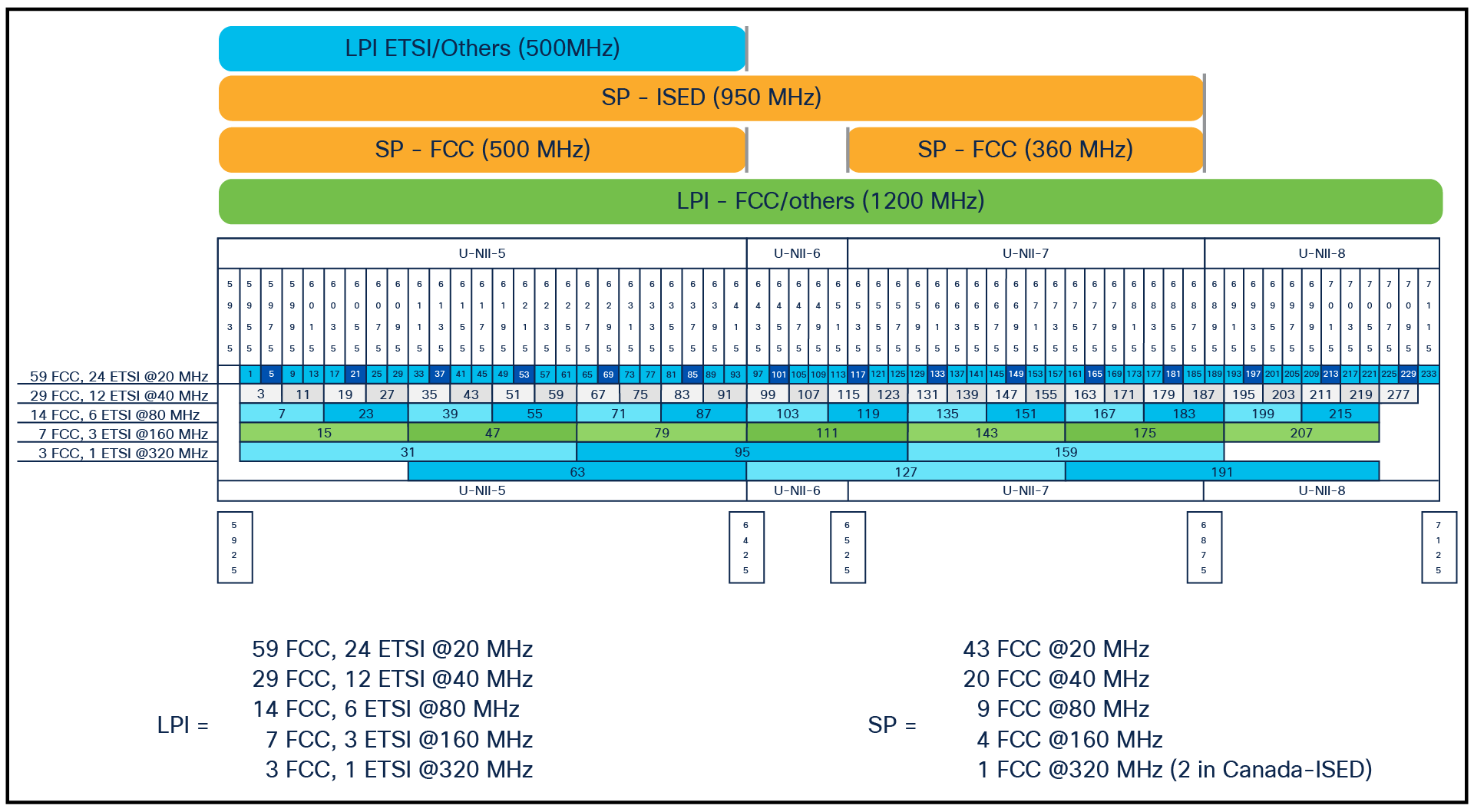
Channel plan for Wi-Fi in 6 GHz through Wi-Fi 7
Wi-Fi 6E and 6-GHz spectrum created the possibility for a practical 320-MHz-wide channel width. A wider channel is a multiplier for data; a 320-MHz channel has twice the capacity of a 160-MHz channel. Channel bonding comes at a cost of increased noise floor. For Wi-Fi 6E in the US, Canada, and other countries, this is taken care of by adding 3 dB to the maximum Effective Isotropic Radiated Power (EIRP) on every channel when doubling the channel up to 320 MHz. In regions where there is a fixed maximum Power Spectral Density (PSD), this has to be accounted for in the design.
Depending on the region of the world, there can be as few as one 320-MHz channel. At the most there are three available in a 1200-MHz allotment. The use of three channels here has the same implications as it did in 2.4 GHz, with the advantage that 6 GHz does not propagate as far as 2.4 GHz. In a dense-capacity network, it can lead to high channel reuse rates, co-channel interference, and poor performance. Some care must be taken in the design.
Are 320-MHz channels practical now? Time will tell—especially if spectrum availability can keep up with demand. However, with the advancements in Wi-Fi 6E and Wi-Fi 7, there’s never been a better time in Wi-Fi history to take advantage of wider channels.
Note: A qualified assessment should be undertaken before making design and deployment changes. Mishandling the channel plan can result in diminished performance. Cisco’s Dynamic Bandwidth Selection is capable of evaluating the opportunities in real time and assigning wider channel widths where they can be supported.
Multi-Link Operation is a fundamental sea change in Wi-Fi. As revolutionary as OFDMA was to Wi-Fi 6 with its multiuser PHY, MLO will change the way we think about Wi-Fi. In previous generations of Wi-Fi, a client device was permitted to associate and pass data in only one band (2.4, 5, or 6 GHz). MLO permits the distribution of traffic across multiple bands, which increases transfer speeds and reduces latency while providing improved reliability and efficiency.
It does this through the access point Multi-Link Device (AP MLD), which manages the access requests and sessions coming in from the non-AP MLD (client) devices.
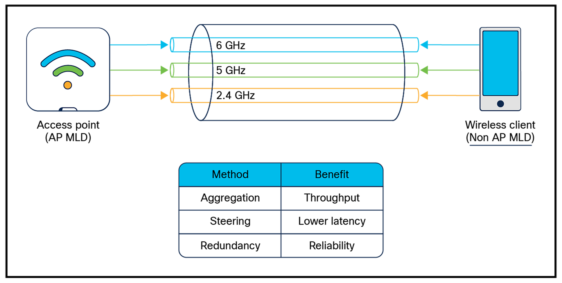
AP to non-AP MLDs
MLO provides multiple benefits to latency-sensitive applications such as augmented reality/virtual reality (AP/VR), where even a modest increase in latency can cause user discomfort. Wi-Fi 7 client devices come in all configurations, from single to multiple (two and three) radios per device.
Regardless of configuration, Wi-Fi 7 MLO includes modes of operation designed to deliver benefits across all device types.
Wi-Fi 7 Multi-Link Operation (MLO) Modes:
● Multi-Link Single Radio (MLSR): The client can switch between bands seamlessly but can transmit or receive on only one band at a time.
● Enhanced Multi-Link Single Radio (EMLSR): Allows transmission on only one band at a time, but a 2-spatial stream client can receive on two different bands simultaneously.
● Multi-Link Multi Radio (MLMR): Includes two modes of operation:
◦ Simultaneous Transmit and Receive (STR): The client can independently transmit and receive on two separate bands at the same time.
◦ Non-Simultaneous Transmit and Receive (nSTR): The client can transmit or receive on both radios, but not simultaneously. (Note: This mode is not included in Wi-Fi 7 certification.)
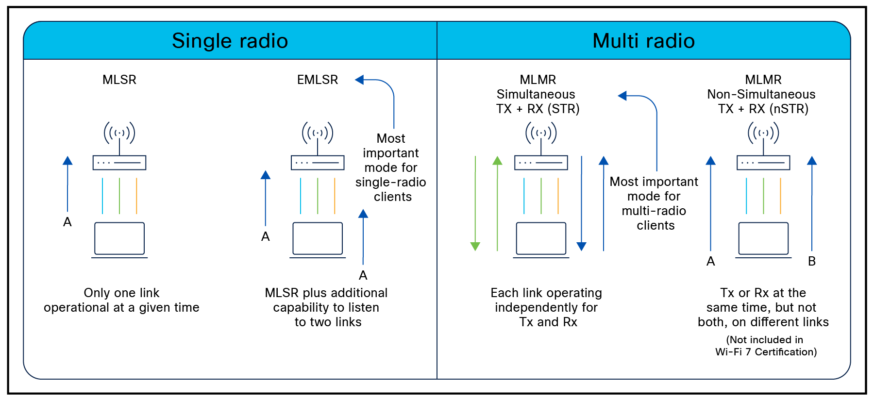
Modes of operation for MLO in today’s client base
Note: Not all clients are created equal. RF isolation between 5- and 6-GHz radios will determine the operational capabilities. For instance, a client supporting MLMR-STR may do so as 2.4 and 5 GHz or as 2.4 and 6 GHz but may not allow 5 and 6 GHz because of internal interference.
When Wi-Fi 6 introduced OFDMA modulation, the concept of the resource unit or RU and the ability to transport more than one user’s data in a single transmission period became available. RUs are made up of different numbers of the subcarrier frequencies that make up the Wi-Fi channel. A 20-MHz Wi-Fi channel contains various RU sizes from 26 to 242 tones or subcarriers. These can be mixed and matched to fit the user’s data needs and maximize the efficiency of each Transmit Opportunity (TxOp). In Wi-Fi 6, a single user can occupy only a single RU (26 to 996) during any TxOp. If any RUs are left empty because no data will fit them, they are padded to prevent sending them empty. That’s wasteful.
MRU enables Wi-Fi 7 to assign more than one RU per user. Removing the Wi-Fi 6 limitation of a single user per RU allows better efficiency and reduces wasted RUs by permitting the scheduler to fill all RUs with user data instead of null characters. Figure 5 shows the Wi-Fi 7 frame accommodating the additional RU 242 for the same user as the RU 484. In Wi-Fi 6, the remaining 242 would have been forced to ride on the next frame, delaying that data’s arrival.
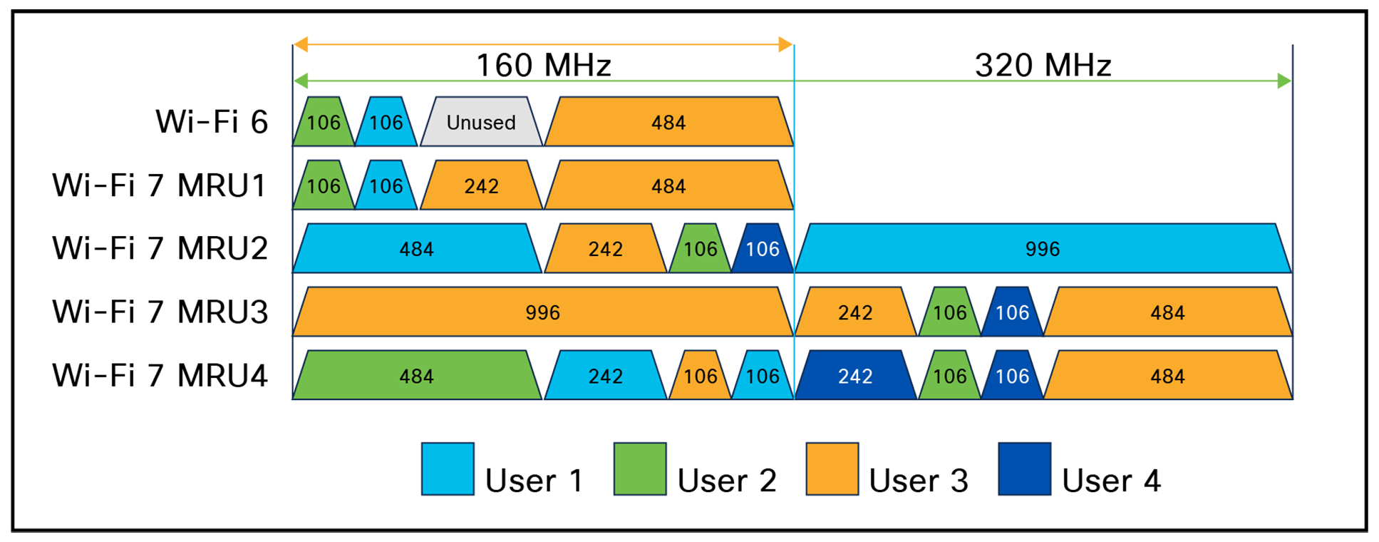
Efficiency gains in user RSU mapping in Wi-Fi 7 MRU compared to Wi-Fi 6
MRU is another iteration of the work Wi-Fi 6 and OFDMA started. It improves the efficiency of the scheduler to allow more user data and further reduce waste. Higher-spectrum efficiency means faster speeds and more deterministic latency over a wide range of user loads.
With the introduction of the 6-GHz band and Wi-Fi 6E, Wi-Fi gained enough spectrum to practically operate some of the wider channel options that were impractical in 5 GHz. However, the probability of encountering interference is proportional to the channel width. This makes finding a large chunk of noise-free spectrum more difficult. Wi-Fi 7 introduces “preamble puncturing,” which allows a device to selectively ignore a problematic portion of a channel—effectively removing it from use without impacting the rest of the transmission. Previously this required pruning the channel at the interference point and could leave a lot of spectrum on the table. Preamble puncturing greatly improves the chance of deploying wider channels reliably.
For all Wi-Fi 7 deployments, puncturing resolution is fixed at 20 MHz and is supported on channel widths of 80 MHz and above. In the 6 GHz band, puncturing is a mandatory requirement, while in the 5 GHz band, it remains optional.
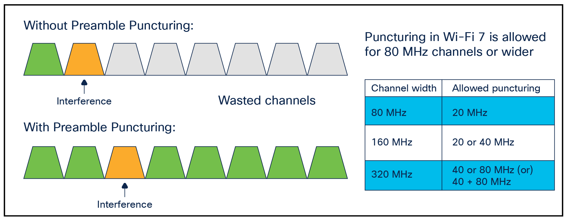
Preamble puncturing example, showing the preservation of 100 MHz of spectrum
In Wi-Fi 6, Target Wake Time (TWT) was introduced as a new power-saving mode, extending the work that was previously done in 802.11ah for devices with low traffic volumes (such as IoT devices). TWT provides two ways that a station (STA) can coordinate a time to wake up and transmit data to the AP. This allows a STA to save power and “sleep” until it wakes up on schedule to transmit.
● Individual TWT: Allows the STA to negotiate with the AP for an agreed time slot.
● Broadcast TWT: Transmits a “trigger” on a regular schedule and allows any STA to sync on that schedule.
Individually negotiating with each client isn’t scalable in larger networks, while broadcast TWT—though effective—offers no mechanism to coordinate multiple stations or distribute them efficiently to maximize airtime opportunities.
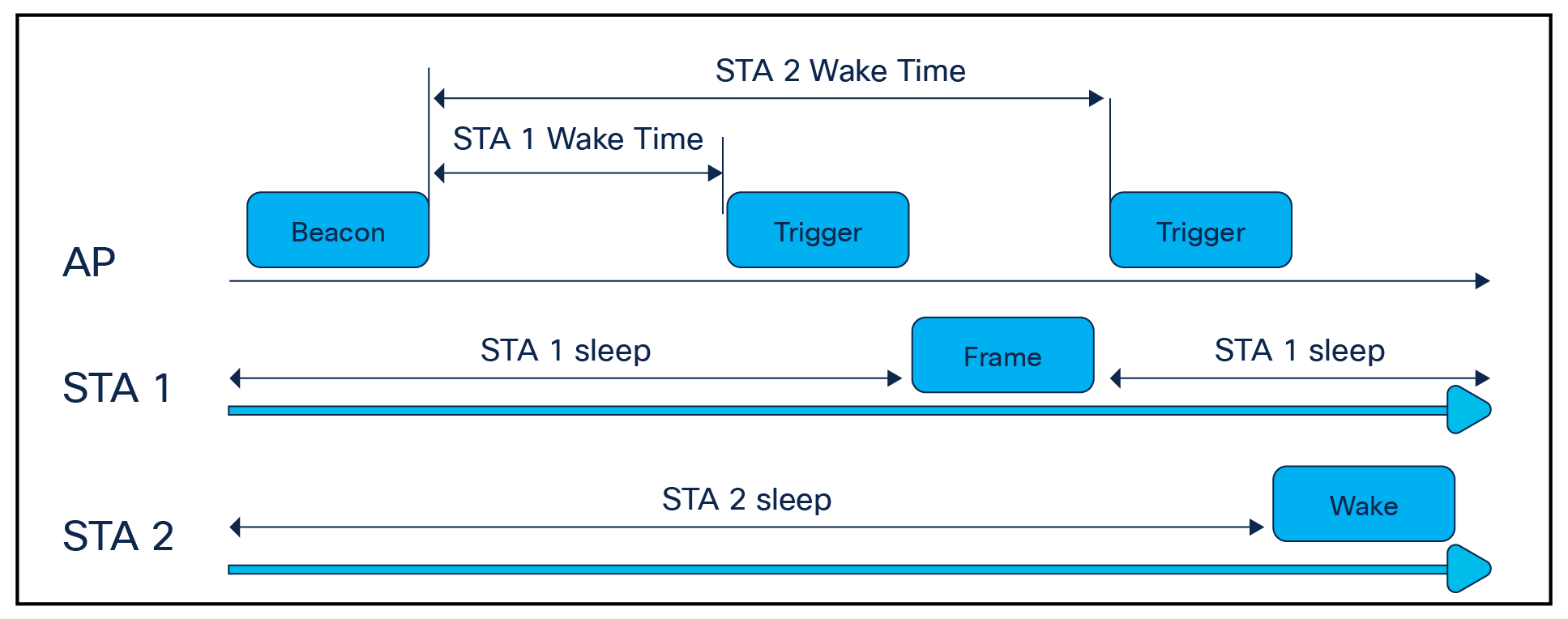
TWT operations
Wi-Fi 7 introduces Restricted TWT or R-TWT, which improves on the previous specification by defining a multilink TWT mechanism based on Wi-Fi 7 and MLO technology. R-TWT is for latency-sensitive traffic and allows APs to use improved channel access and resource reservations to protect such packets. This will provide more predictable latency and improved jitter while also reducing the worst-case latency experienced when the channel is crowded.
Efficiency and Performance Enhancements
Wi-Fi 7 Efficiency Enhancements
Wi-Fi 7, like most recent protocol releases, builds on previous enhancements, driving more efficiency. Consolidating some of the unused features from earlier releases reduces the variables a radio has to deal with while driving more function into existing protocol structures. For instance, Wi-Fi 6 defined four new physical layer Protocol Data Unit (PPDU) types to accommodate the new capabilities built into the specification:
● HE SU PPDU – Designed for single-user packet transmissions.
● HE MU PPDU – Used for multi-user packet transmissions.
● HE TB PPDU – Supports trigger-based operations for uplink OFDMA and uplink/downlink
● MU-MIMO. The “trigger” frame includes resource allocations to synchronize simultaneous uplink transmissions from multiple users.
● HE ER SU PPDU – Optimized for Extended Range (ER) scenarios.
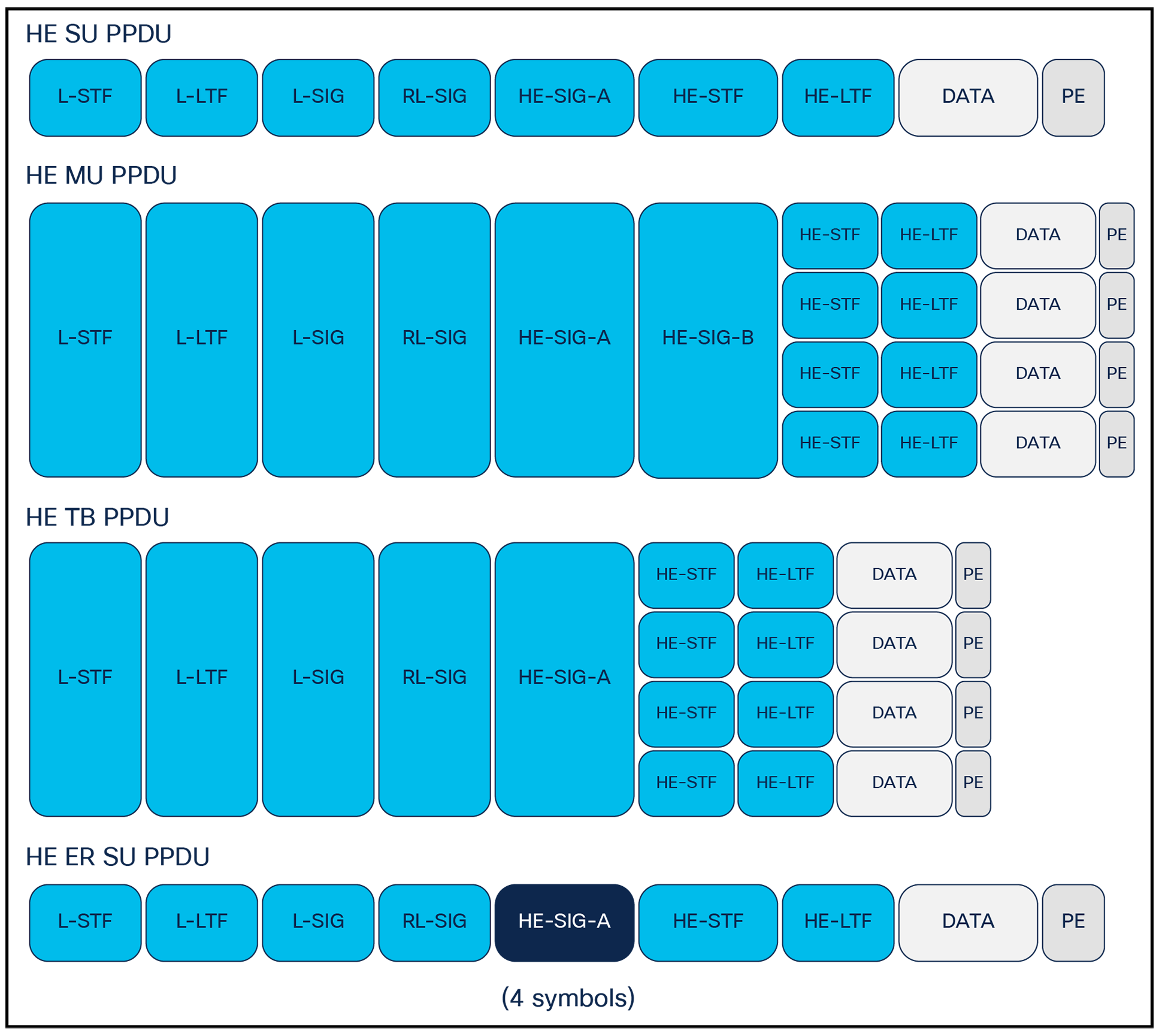
Wi-Fi 6 frame maps
Wi-Fi 7 consolidates some of these definitions by first combining both the HE SU and HE MU PPDU types into a single PPDU type called the EHT MU PPDU. The new PPDU type may be used for either SU or MU PPDUs. There is also a new Universal SIG field (U-SIG) defined to contain PHY version information that will provide forward compatibility with various new PPDU types in the future. The HE TB PPDU is also redefined in Wi-Fi 7 as the EHT TB PPDU, and the HE ER SU PPDU is dropped.
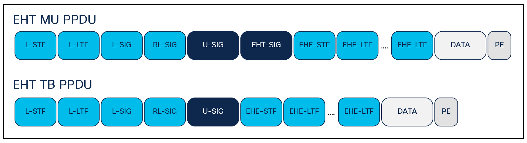
Wi-Fi 7 native frame types
Wi-Fi 7 builds on this structure by reducing the kinds of PPDUs down to two “variable” PPDU types. It also adds functionality to ensure “forward” compatibility. This reduces receiver complexity by limiting variations in PPDU types, while maintaining flexibility for upper-layer protocols to manage traffic effectively.
Designing Considerations for Wi-Fi 7
Do all these advances in spectrum (Wi-Fi 6E) and technologies (Wi-Fi 6/7) change how we fundamentally think about the network design? The answer is yes, if you are building a ground-up greenfield network that has only Wi-Fi 7 clients operating on it in an isolated space.
For the rest of us, not so much. Now this assumes that you have kept pace with growth and your maximum uplift is a well-tuned Wi-Fi 5 network. If the network has coverage and capacity issues today, simply replacing the APs with the latest specification is not likely to improve things much. The longer it’s been since the last proper evaluation and planning cycle, the more likely it is that you will need to ensure success. Problems with coverage and roaming generally will not improve with a new AP in the same place as the old. But the capacity will likely improve under the new one.
Many large enterprises report 30% of the client base are 6-GHz-capable today. Shifting clients to 6 GHz reduces the number of clients operating at 5 GHz and improves the experience for the remaining users. In todays networks client mixes are often as high as 60%/40% Wi-Fi 6/Wi-Fi 5 devices. As Wi-Fi 5 devices continue to age out completely, the capacity and reliability of Wi-Fi networks will only continue to improve as we expand into 6 GHz.
To fully take advantage of what Wi-Fi 7 and beyond have to offer, it’s important to align your deployment strategy with the evolving demands of modern networks. Here are the top five priorities to consider when planning for next-generation Wi-Fi deployments:
Deployment Priorities for Wi-Fi 7 and Beyond
1. 6 GHz
2. Switch port Power over Ethernet (PoE)
3. Switch port speeds
4. Location technologies/smart buildings, IoT
5. Access layer security and strategy
The most significant impact to current network designs is the introduction of the 6 GHz band. As an entirely new spectrum, it comes with new rules, unique propagation characteristics, and fresh opportunities. How you deploy 6 GHz today will influence how it evolves and scales in the future. Since the spectrum is still new, policies and best practices are still taking shape—making this the perfect time to consider who should have access and how that access will affect existing bands as more devices adopt 6 GHz.
Spectrum is an incredibly valuable resource. Major carriers have spent millions acquiring just 100 MHz of licensed spectrum—yet Wi-Fi 6E and Wi-Fi 7 unlock between 500 and 1200 MHz of unlicensed spectrum at no cost. That makes questions like What is our band policy? and What does coverage look like? all the more important. Will your current 5 GHz coverage model support a similar density of 6 GHz APs? How will this affect roaming and overall capacity?
Most enterprise spaces today have ubiquitous coverage established for Wi-Fi in both the 2.4- and 5-GHz spectrums. Typical access point (AP) density ranges from one AP per 1,000 to 2,000 square feet (92 to 185 square meters), with average spacing between APs of 36 to 50 feet (11 to 15 meters). If your environment doesn’t meet these standards, consider this the minimum baseline for modern enterprise Wi-Fi deployments.
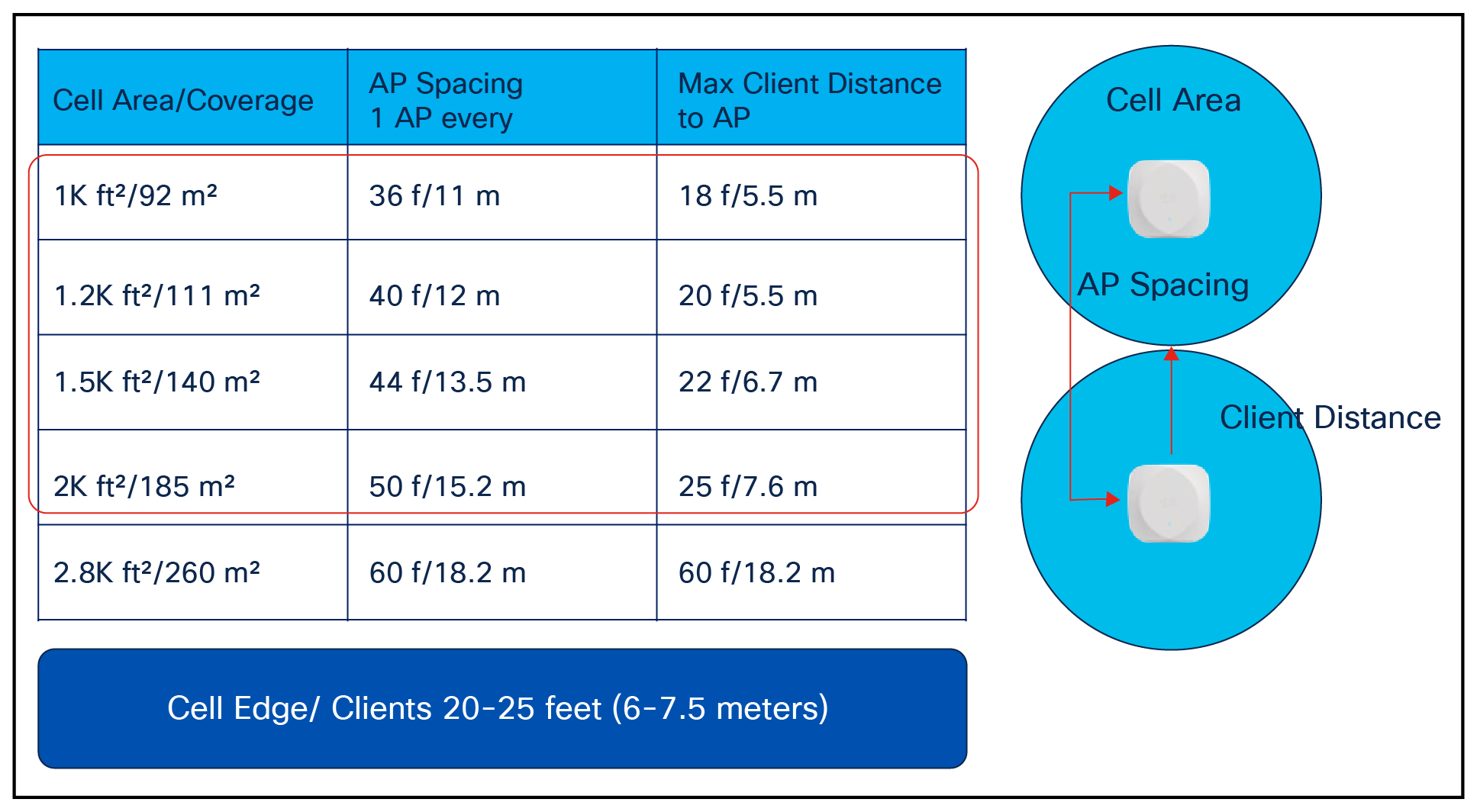
Average AP distance and coverage trends
The 6-GHz spectrum is not vastly different from the 5-GHz spectrum. In terms of the physics, 2.4 and 5 GHz are much farther apart than 5 and 6 GHz. 6 GHz is a higher frequency, and that means it doesn’t go as far or penetrate objects as well as a lower frequency will. The difference between 5 GHz and 6 GHz in free space path loss is ~2 dB. This means you will need 2 dB more power with 6 GHz to achieve the same distance, assuming all else stays equal. This also assumes free space or line-of-sight operations. It is advisable to maintain equitable cell sizes between 5- and 6-GHz interfaces on the tri-band APs, as this will best facilitate equitable roaming regardless of the current band of operations.
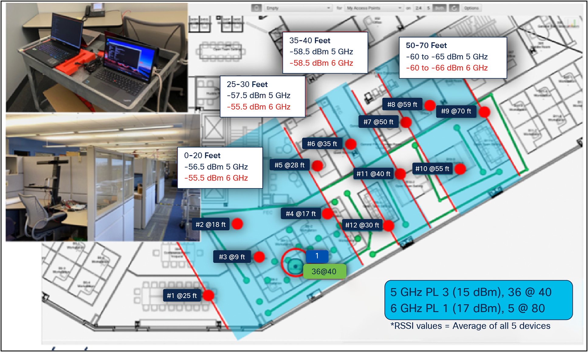
Comparing 5- and 6-GHz client reception at various locations across a carpeted (and cubed) office space using an AP with 2 dB more power in 6 GHz than in 5 GHz. Distance from the source is shown on each test point.
If coverage is being provided by an AP located behind a wall or other obstruction, it’s best to measure the signal strength to ensure adequate performance. Penetration power is variable and changes with the angle and the distance traveled through the object. At a minimum, use a predictive planner, conservative settings, and accurate maps to evaluate coverage requirements. If a proper design has never been done, or things have changed since it was done, do a measured passive survey and start with a good baseline to ensure success.
On average across Cisco’s data lake and regardless of market vertical, 80% of configurations report power levels between 11 and 15 dBm on their 5-GHz APs. Most carpeted office spaces are operating in the 2 to 8 dBm range for 5 GHz. So barring any obstructions, this means 80% of existing spaces can be adequately covered today, with perhaps 10% to 15% new APs needed in the worst cases.
In most cases, indoor deployments will be governed by Low Power Indoor or LPI rules. 6-GHz rules make restrictions on 6 GHz outdoors; it’s simply not allowed outdoors without Standard Power (SP) mode. Operating in SP mode requires an Automated Frequency Coordination (AFC) function that most have not implemented. This and other power- and antenna-intensive solutions like high ceilings (26+ feet, or 8+ meters), atriums, and warehousing will require different rules and more power. In the United States, the use of SP mode and the AFC were just permitted in 2024, with Canada set to follow shortly. SP mode allows for coverage outdoors, supports external antennas, and allows for higher power levels—ideal for use cases that require extended range or enhanced performance.
It is important to know the regulatory rules where the deployments are taking place. In all cases, the operator of the network is legally responsible for the outcomes. In the case of 6 GHz, the devices that could get interfered with are owned by people who will notice and can determine the source.
Power over Ethernet (PoE) is becoming increasingly important as its requirements continue to evolve. The newest APs support multiple technologies (Wi-Fi, sensors, USB, Ultra-Wideband [UWB] and IoT, Multigigabit) and they simply require more power. The original standard was 802.3at at a modest 15.4W, then 20W and 30W to support multiple-stream radios in three bands. And since the introduction of Wi-Fi 6E, it is best to plan for 802.3bt power or 60W ports. This provides ample power for the AP to function reliably, with enough headroom for additional demands. Today’s flagship access points may support up to 16 Wi-Fi radio streams, along with dedicated radios for monitoring and IoT, plus dual 10 Gbps Multigigabit Ethernet ports. Add to this the compute power and memory required to process and manage the dense data streams, and the power budget inevitably has to go up.
Most vendors offer modes to reduce the effective power requirements of the radios. This is intended to ease the transition by allowing more operational flexibility to accommodate differing implementation cycles. But consider that this reduction comes at the cost of performance. Most modern client devices come equipped with two spatial streams. Reducing the AP’s operating radios from four to two spatial streams not only halves the potential throughput but also eliminates the possibility of leveraging Multiuser Multiple Input, Multiple Output (MU-MIMO). Increasingly, however, the issue isn’t average throughput—it’s latency. Latency is load-dependent and increases as demand rises. With finite resources, more users mean longer wait times. To avoid performance issues, always design for peak demand—so you won’t be left explaining why the network struggles under pressure.
Switch port speeds matter. Switches do an amazing job of balancing the bursty nature of wired and wireless traffic while managing congestion surges within the fabric. Creative buffering and advanced algorithms provide a smooth and consistent feel to the increasingly demanding applications we use. It is even possible to overload the switch for periods of time and still get consistent results with many applications.
Increasingly, though, video conferencing is a major player on a daily basis across the industry, and these applications do not like buffering. Design limits of 50 ms or less latency and less than 30 ms jitter are the current best practices across the industry. For AR/VR applications, less than 10 ms latency is required to avoid user discomfort. At any given time, most adequately designed office networks can hit these kinds of latency numbers, but they need to do it sustainably. In other words, can performance be maintained when a district-wide meeting is taking place in the office, with employees watching both the live event and its simultaneous video stream?
From a technology perspective, available resources continue to expand rapidly. In just the past few years, we’ve seen the introduction of more spatial streams, higher data encoding densities (1024- and 4096-QAM), advanced techniques like MU-MIMO, R-TWT, and BSSID coloring, wider channels up to 320 MHz, and now the ability for clients to communicate with multiple radios simultaneously through Multi-Link Operation (MLO). On top of that, we now have access to an entirely new spectrum: 6 GHz.
All of these advancements make it relatively easy to exceed 1 Gbps, even with 2.4, 5, and 6 GHz radios operating simultaneously across four spatial streams and supporting 50 users. However, when devices hit their limits, it often manifests as brief pauses or “glitches”—and in more severe cases, video freezes or application failures.
The most capable Wi-Fi 7 APs can manage 10 Gbps over the air. Running a 1 Gbps port speed and disabling radios to save power is not going to give the newer, more capable clients what they need to operate efficiently, so it is unlikely that even with new APs and clients the congestion on the network will change much. Enabling 6 GHz will shift some users to 6 GHz and free up some 5-GHz airtime, but that will cost more power too.
Location Technologies, Smart Buildings, and IoT
Many of today’s APs support technologies other than Wi-Fi as well. The convenience of using the AP as the platform from which to manage and deploy other technologies increases its value in the infrastructure. Using the AP’s power and network interfaces avoids the need for additional cabling and secondary access systems, but this approach may not integrate well into your security strategy. Using the AP as the platform eliminates that concern and reduces the threat surface over multiple independent systems. While these advancements offer significant benefits, it’s important to design with the requirements of all technologies in mind. For example, if you operate a large IoT network, you’ll need to ensure consistent coverage in all areas where IoT devices are deployed—even in spaces without regular human presence. Similarly, for a Real-Time Location System (RTLS) using asset tags, 2.4 GHz coverage must be enabled throughout all tracked areas.
Many organizations are implementing smart buildings to better manage resource availability and provide a safer environment. One of the best examples of how this might influence design is indoor navigation to help visitors and employees find their way efficiently through facilities. Wi-Fi-based location has been around for a long time. However, the limitations of Wi-Fi navigation accuracy have driven other alternatives such as Bluetooth Low Energy (BLE), Ultra-Wide Band (UWB) and Fine Time Measurement (FTM). All of these technologies improve the accuracy and resolution between the signal sources in different ways. They all require different radios deployed in a fixed matrix to resolve where the client is in relation to the network. The AP, as a source of power and network access, has long been an attractive option for deploying these technologies.
Wi-Fi networks provide network access to end users and tend to be built for capacity around the areas where users congregate and spend most of the day. Transition areas like hallways, outer wall edges, corners, and lobbies all require less capacity and frequently are taken care of by extra energy that leaks into the area, since it rarely requires much capacity. However, these areas are important to navigation, and as such they need reference points in the right places to provide adequate accuracy where navigation is desired. The concept of a convex hull has often been used to described Wi-Fi location design. This concept just states that the best location accuracy occurs from somewhere inside of the “hull” that would result from a line wrapped around all of the APs in a given space.
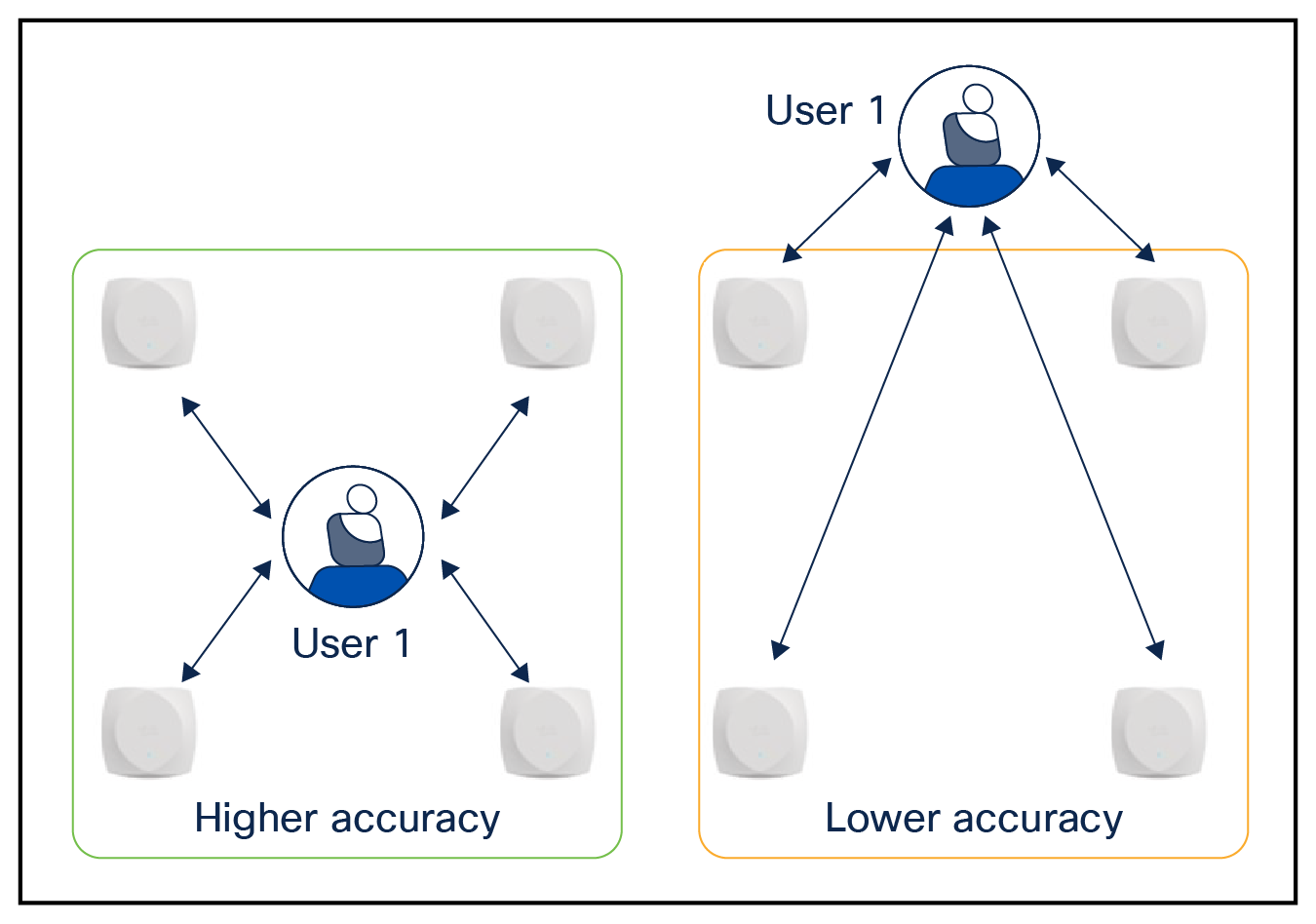
Providing more accurate location resolution using the convex hull concept
In order to provide accurate location resolution, all radio technologies require coverage that includes placement near the edges of walls and choke points (ingress and egress points) to provide context that covers the needs of the application. When looking at the needs of your network going forward, evaluate current network placements against the requirements. In most cases, moving some APs and perhaps adding a few at choke points will enable excellent resolution and coverage without interference.
Access Layer Security and Strategy
One thing that the newest Wi-Fi protocols take seriously is security. All things Wi-Fi 6E and beyond require the use of Wi-Fi Protected Access 3 (WPA3) at a minimum. WPA3 was originally released in 2018 and has been mandatory for all infrastructure devices carrying the Wi-Fi certified label since 2020. While WPA3 has been mandatory for all certified infrastructure devices since 2020, client adoption has lagged behind. Many devices still ship without WPA3 support, creating gaps in overall network security.
In most environments, there’s limited control over which client devices attempt to join the network at any given time. Some legacy technologies—such as the earliest version of WPA or Wired Equivalent Privacy (WEP)—are outdated and should no longer be permitted. However, many devices still rely on WPA2 and, while they may not support the latest standards, they remain functional and valuable and often need to be accommodated.
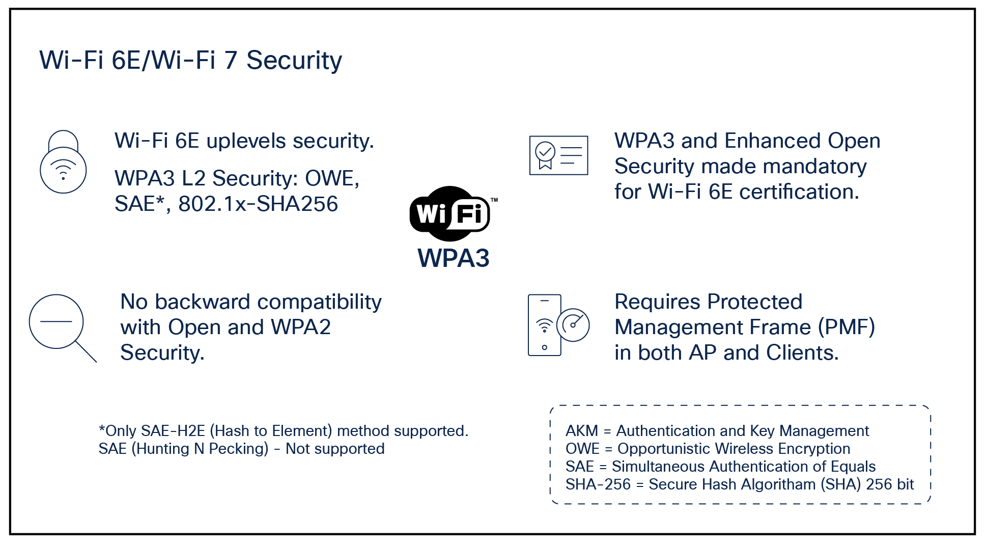
Wi-Fi 6E/Wi-Fi 7 access requirements
For network operators navigating mixed client environments—a common challenge—there are three main strategies to enable secure coexistence:
1. Go All In
Reconfigure the existing WLAN to require WPA3 on a single SSID, applying the policy across all three bands.
Pros: Simplifies the network and ensures full compliance.
Cons: Can be disruptive if the client base isn’t fully WPA3-ready. WPA3 also requires Protected Management Frames (PMF), and some devices may support WPA3 but still lack full Wi-Fi 6E compatibility.
2. Use Multiple SSIDs
Create a dedicated SSID with advanced security settings for newer clients that can fully leverage 6 GHz access, Multi-Link Operation (MLO), and 802.11be data rates, while keeping a separate SSID for legacy devices.
Pros: Enables advanced users to benefit from modern capabilities while freeing up airtime on 2.4 and 5 GHz for less efficient devices.
Cons: Increases network complexity and management overhead.
3. Use Transition Mode on a Single SSID
Configure one SSID with WPA2/WPA3 transition mode, supporting both modern and legacy clients. This includes Authentication and Key Management (AKM) settings such as 802.1X-SHA256 and 802.1X (SHA1) for enterprise networks, and Simultaneous Authentication of Equals (SAE) plus Pre-Shared Key (PSK) for personal networks. PMF should be set to optional.
Pros: Simplifies network management by reducing the number of SSIDs.
Cons: Some older clients may struggle with compatibility or misinterpret the mixed settings.
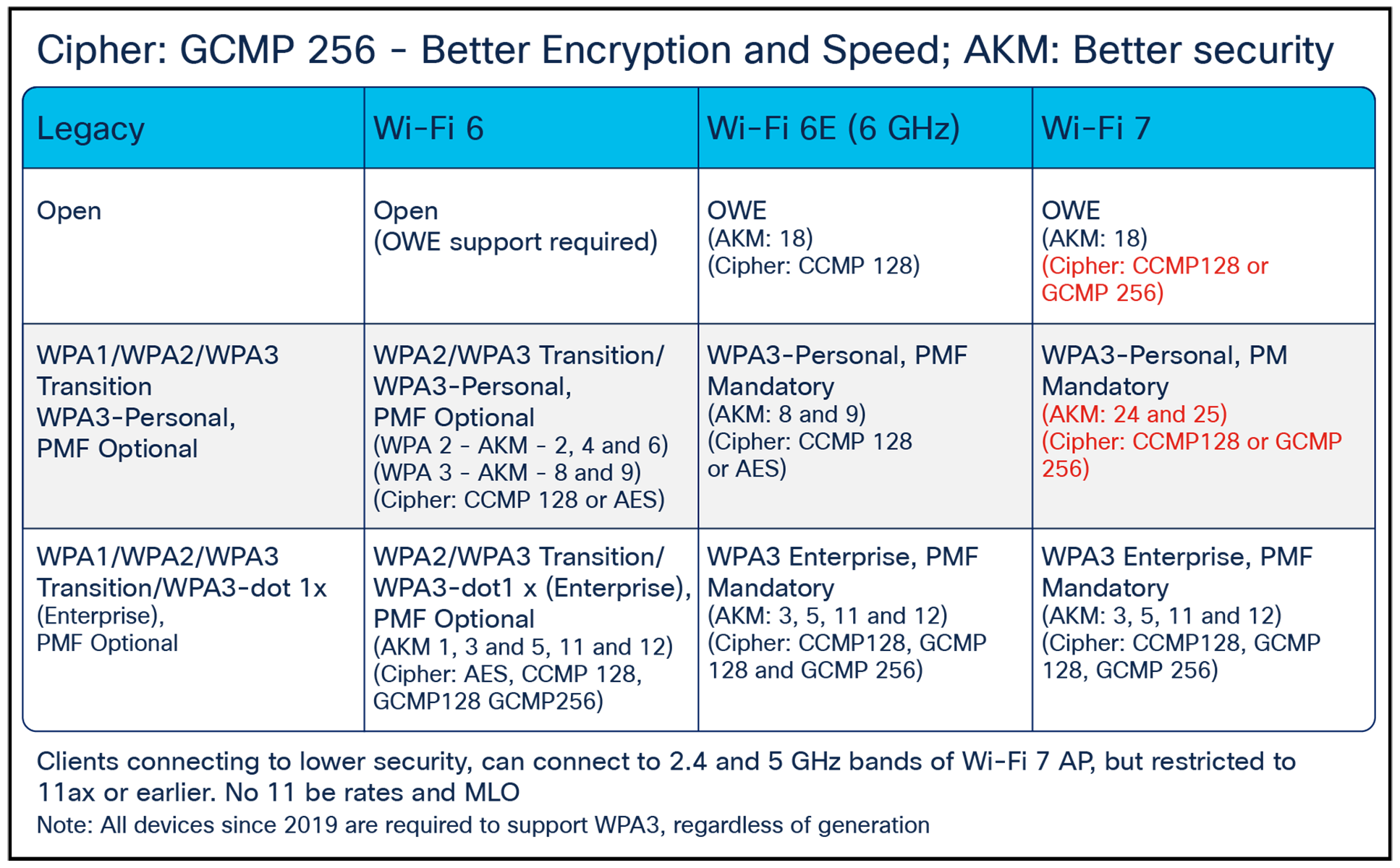
Wi-Fi standard and minimum security requirements comparing legacy with Wi-Fi 6 and beyond
Designing for the Future of Wi-Fi
As Wi-Fi continues to evolve with advancements like Wi-Fi 6E, Wi-Fi 7, and the expansion into the 6 GHz spectrum, network design and deployment strategies must also adapt. These new technologies bring powerful capabilities—from higher throughput and lower latency to greater efficiency and more intelligent resource allocation. However, unlocking their full potential requires thoughtful planning around spectrum use, infrastructure readiness, security policies, and client capabilities.
Whether you’re building a greenfield deployment or modernizing an existing network, success hinges on designing for peak performance, accommodating a range of client devices, and aligning your strategy with the demands of today’s increasingly connected environments. The future of Wi-Fi is here—make sure your network is ready to support it.