PoE for Industrial Automation: Power, Data and Control over a Single Cable Solution Brief
Available Languages
Bias-Free Language
The documentation set for this product strives to use bias-free language. For the purposes of this documentation set, bias-free is defined as language that does not imply discrimination based on age, disability, gender, racial identity, ethnic identity, sexual orientation, socioeconomic status, and intersectionality. Exceptions may be present in the documentation due to language that is hardcoded in the user interfaces of the product software, language used based on RFP documentation, or language that is used by a referenced third-party product. Learn more about how Cisco is using Inclusive Language.
It has been 20 years since the first Power over Ethernet (PoE) standard was ratified by IEEE. Called IEEE 802.3af, this first standard provides up to 15.4W of DC power per port. With this standardization, PoE quickly gained popularity, as it enabled a reduction in infrastructure costs, simpler installation, greater flexibility, and increased reliability. It also allowed organizations to better optimize power consumption by being able to use the network to control power to connected devices. The first implementations had narrow applicability, and IEEE has introduced newer standards over the years, with the latest, IEEE 802.3bt Type 4, also called 4-pair PoE (4PPoE) or PoE++, able to supply up to 90W per port.
After its initial deployment in enterprises, PoE is now becoming popular in the industrial sector, where devices frequently require higher wattage and better control, and where sustainability issues are front and center.
To take full advantage of PoE, and to facilitate its rollout on a large scale, organizations must properly plan its deployment, considering the right power sources, proper cabling, and network design. They also need to be able to monitor, manage, and troubleshoot promptly to help ensure uninterrupted operations.
This paper explains the basics of PoE, explores how the industrial sector can benefit from PoE technology, and describes the PoE capabilities that Cisco® industrial switches offer and the tools available for proper design, monitoring, and deployment.
PoE works by injecting low-voltage Direct Current (DC) power into an Ethernet cable, alongside the data signals. This power is then extracted at the receiving end by compatible PoE-enabled devices, which can use power supplied through the Ethernet cable to operate without requiring a separate power source.
In PoE nomenclature, Power Sourcing Equipment (PSE) refers to the entity that injects power into the Ethernet cable, and Powered Device (PD) refers to the device that consumes power.
Typically, the PSE is an Ethernet switch, but it can also be a special power injector that is distinct from the switch. In this document, we will assume that the PSE is an Ethernet switch.
An Ethernet cable contains multiple copper conductors. These conductors are twisted together to reduce interference from external sources. The most common type of Ethernet cable, known as twisted pair cable, consists of four pairs of twisted copper wires. The early PoE standard, IEEE 802.3af, uses two of the four pairs to deliver power, while the data transmission occurs over the remaining two pairs. Later standards use all four twisted pairs in an Ethernet cable for power transmission and can provide significantly higher power levels compared to previous PoE standards.
The benefits of PoE include simplified installation and deployment, as it eliminates the need for additional power outlets near devices. It also allows for easier scalability and flexibility in network infrastructure design, as devices can easily be added or relocated without the need to worry about power outlets. Additionally, PoE provides centralized power management and can enhance reliability and continuity of power delivery by providing backup power options for the source.
Sustainability
PoE can reduce costs and increase sustainability in several ways.
● PoE eliminates the need to run extra copper cabling and steel conduits to each device.
● PoE delivered through network equipment allows for easy monitoring and control of power consumption. Power can be shut off or reduced to nonessential devices when they are not in use.
● AC-DC conversion losses, which could add up to 20%, can be avoided by using PoE to power devices that natively run on DC.
● PoE delivered through ruggedized networking equipment helps reduce overall cooling costs.
Safety
PoE can also help make industrial operations safer. The factors that enhance safety include:
● PoE operates at a lower voltage, typically 48V, which is considered safe for handling by individuals, whereas traditional power cables can carry higher voltages, increasing the risk of electrical shock or electrical hazards if not handled properly.
● PoE reduces the risk of short circuits, exposed wires, or accidental contact with high-voltage wires that can occur when running separate power cables.
● PoE devices are designed to provide overload protection, which defends against excessive power consumption and potential damage to devices or cables.
● PoE switches and devices have built-in safeguards that monitor power usage and can shut down or limit power delivery if an overload is detected, protecting the connected equipment and reducing the risk of overheating or fire.
● PoE technology adheres to safety standards and procedures, ensuring that PoE-enabled devices, cables, and PSE meet specific safety regulations. Compliance with these standards helps ensure that PoE installations are safe and reliable.
AI and innovation
PoE acts as an enabler for Industrial AI by making it practical and affordable to deploy the distributed network of cameras, sensors, and other edge devices that provide the essential raw data feedstock for AI models to deliver insights, predictions, and automated actions. Without the deployment ease offered by PoE, gathering the necessary data across a large industrial facility would be a far more complex and costly endeavor.
PoE standards
IEEE has defined several PoE standards since the first standard, IEEE 802.3af, was ratified in June 2003. Table 1 shows the current IEEE standards and the maximum power they are rated for. Note that for 30W or higher, a 4-pair Ethernet cable is required, since all pairs are necessary to deliver the power.
Table 1. IEEE standards defining PoE
| IEEE PoE standard |
Description |
| IEEE 802.3af (PoE) |
● Supplies up to 15.4W of DC power
● Uses two of the four pairs in the Ethernet cable
|
| IEEE 802.3at (PoE+) |
● Supplies up to 30W of DC power
● Uses two of the four pairs in the Ethernet cable
● Backward compatible with IEEE 802.3af
|
| IEEE 802.3bt (PoE++ or 4PPoE) |
● Supplies up to 60W or 90W of DC power (depending on implementation)
● Uses four pairs in the Ethernet cable
|
Before the IEEE standards came into force, Cisco developed its own PoE standards. The Cisco Universal Power over Ethernet (Cisco UPOE®) standard, a precursor to IEEE 802.3bt, delivered up to 60W per port. The Cisco UPOE+ standard, delivering up to 90W per port, combined the IEEE 802.3bt standard with Cisco UPOE, which means that Cisco UPOE+ switches are in complete compliance with IEEE 802.3bt and all previous standards, such as IEEE 802.3af and IEEE 802.3at, as well as Cisco UPOE.
Figure 1 Illustrates the PoE standards and the typical devices that can be powered through each.
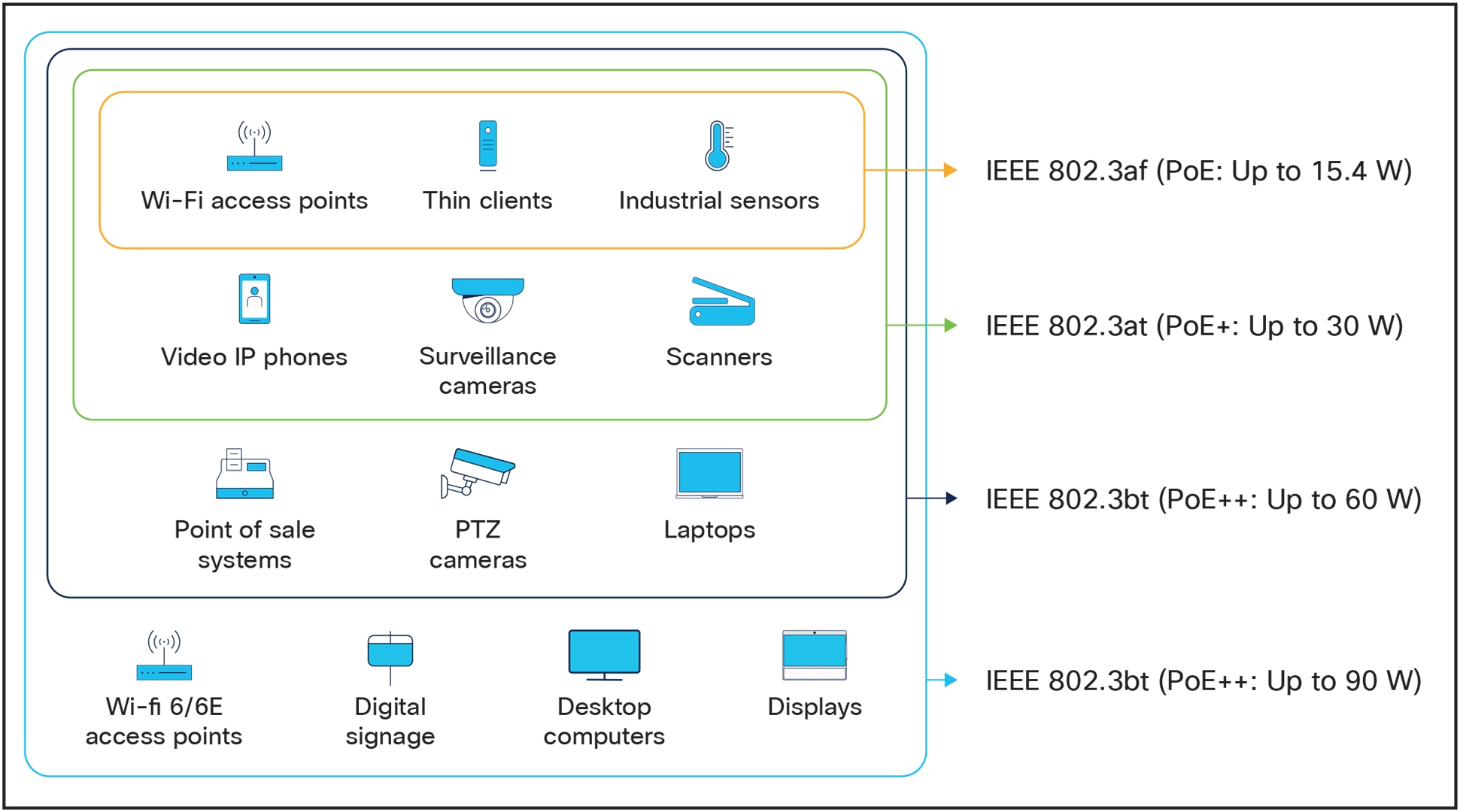
Typical PoE-powered devices
Power availability at powered devices
While the standards specify the nominal power delivered from the PSE, the actual power available at the PD may be less because of losses in transmission. Typically, in enterprise environments these losses are between 10% and 15%. For example, the net available power might be only 51W at the device when connected to a source capable of delivering 60W. These losses may be magnified in industrial environments, as discussed below. The power availability consideration must be part of an industrial network design.
Table 2. Maximum power available for PDs
| PoE standard |
Number of twisted pairs |
Maximum power from PSE |
Maximum power at PD1 |
| 802.3af (PoE) |
2 |
15.4W |
12.95W |
| 802.3at (PoE+) |
2 |
30W |
25.5W |
| 802.3bt (PoE++) |
4 |
60W |
51W |
| 802.3bt (PoE++) |
4 |
90W |
71W |
PoE in industrial environments
The advantages of PoE in enterprises are even more relevant to industrial use cases. In industrial environments, PoE brings more reliability and helps reduce downtime. It can also reduce the need to run high-voltage power cables, which increases operations safety.
However, it can be more challenging to provide PoE in harsh environments. Some of the unique requirements of industrial deployments are listed in Table 3.
Table 3. Industrial PoE deployment considerations
| Criteria |
Industrial requirements and considerations |
| Environment |
Industrial environments can be harsh, with extreme temperatures, moisture, dust, and vibrations. Both the PSE and PDs must be ruggedized and designed to withstand these conditions, and industrial-grade PoE switches are required. In addition, high temperatures can reduce power availability at PDs. If your setting has high ambient temperatures, consider this in your power budgeting calculations. |
| Power requirements |
Industrial devices often require higher power levels. For power-hungry devices such as industrial cameras or Wi-Fi 6/6E access points, higher-power PoE (PoE+) or even 4PPoE may be required. Industrial PoE-equipped switches must have larger power budgets and be able to power more devices through their ports. |
| Safety standards |
Industrial environments often have strict safety regulations and requirements. Ensuring that PoE equipment and installations meet these standards is crucial. Proper grounding, surge protection, and adherence to safety codes are essential to mitigate any potential risks. |
| Cable lengths |
PoE has distance limitations, typically up to 100 meters (328 feet) for standard Ethernet cables, beyond which the signal might degrade. In large industrial environments, where devices may be spread out over long distances, additional network infrastructure, such as repeaters or extra switches, may be needed to extend the reach of PoE, as power dissipation along the way can reduce the net power received by the PD. For best performance and reliability, Cat5e or higher-grade cables are recommended. |
| Interference and reliability |
Industrial environments often have electrical noise and interference from machinery, motors, or electromagnetic fields. This interference can affect the performance and reliability of PoE systems. To minimize interference and increase reliability, proper shielding and grounding techniques are essential. In addition, Ethernet cables should not be run near high-voltage lines or sources of high ElectroMagnetic Interference (EMI), as they can degrade data transmission. |
| Power management |
Industrial environments may have complex power requirements, with varying power demands and criticality levels. Ensuring proper power management and balancing power loads across different devices can be challenging. Advanced power management tools and techniques may be needed to optimize power distribution and avoid overloads. |
| Minimal power disruptions |
Industrial operations are very sensitive to power disruptions that could halt production lines, damage sensitive equipment, lead to data loss or corruption, pose safety risks, or affect product quality. Industrial PoE-equipped switches must be able to maintain a reliable power supply as much as possible to ensure efficiency, safety, and cost-effectiveness. |
| UPS backup |
Uninterruptible Power Supplies (UPS) can be deployed to provide backup power to PSEs in the event of catastrophic power failures. |
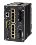
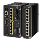
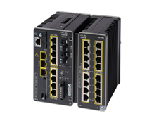
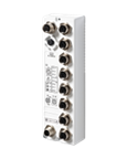
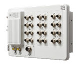
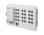
Cisco Industrial Ethernet portfolio
For over 20 years, Cisco has offered a comprehensive portfolio of industrial switches, routers, and wireless devices. Purpose-built for industrial use, these devices provide seamless communications for every industrial sector. Cisco industrial switches are resilient to minimize downtime, support communications protocols between control systems and machinery with minimum delay, and protect operations with visibility, data encryption, and network segmentation. The reader is directed to the data sheet for each switch for the exact specifications for that switch (see Table 4).
PoE support
Several of the Cisco Industrial Ethernet switches are designed to provide PoE to connected devices. There is variation in the supported standard, the number of ports available for PoE, and the total available power budget. Table 4 summarizes the switch characteristics.
Table 4. Cisco Industrial Ethernet switch models and PoE support
| Switch |
PoE (IEEE 803.3af) |
PoE+ (IEEE 802.3at) |
PoE++/4PPoE (IEEE 802.3bt) |
Total ports for PoE |
Total PoE power budget |
Redundant power supplies |
|
| DIN-rail switches |
|||||||
|
|
✓ |
✓ |
X |
Up to 8 ports |
Up to 180W |
✓ |
|
|
|
✓ |
✓ |
✓ |
Up to 8 ports |
Up to 240W |
✓ |
|
| DIN-rail switches |
|||||||
|
|
✓ |
✓ |
X |
8 ports |
Up to 240W |
✓ |
|
|
|
✓ |
✓ |
✓ |
Up to 24 ports |
Up to 480W |
✓ |
|
|
|
✓ |
✓ |
X |
Up to 24 ports |
Up to 480W |
✓ |
|
|
|
✓ |
✓ |
✓ |
Up to 24 ports |
Up to 480W |
✓ |
|
| IP67 switches |
|||||||
|
|
X |
X |
X |
– |
– |
✓ |
|
|
|
X |
X |
X |
– |
– |
✓ |
|
|
|
✓ |
✓ |
✓ |
Up to 14 ports |
Up to 240W |
✓ |
|
| Rack-mount switches |
|||||||
|
|
✓ |
✓ |
✓ |
Up to 24 ports |
Up to 720W |
✓ |
|

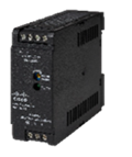
DIN-rail PSUs provide power to DIN-rail switches for switching functions as well as for PoE. You must use the power supply rated for the PoE power you need from the switch. Table 5 lists the available DIN-rail PSUs, IP67-rated PSUs, and rack-mount PSUs and their support for PoE.
Table 5. Industrial power supply units and PoE support
| Power supply unit |
Description |
PoE support |
|
| DIN-rail PSUs |
|||
|
|
PWR-IE50W-AC-L |
50W AC to DC power supply |
No |
|
|
PWR-IE50W-AC |
50W AC to DC or high DC to DC power supply |
No |
|
|
PWR-IE50W-AC-IEC |
50W AC to DC power supply with an IEC connector |
No |
|
|
PWR-IE65W-PC-AC |
65W AC to DC or high DC to DC power supply |
Yes |
|
|
PWR-IE65W-PC-DC |
65W low DC to DC power supply |
Yes |
|
|
PWR-IE170W-PC-AC |
170W AC to DC or high DC to DC power supply |
Yes |
|
|
PWR-IE170W-PC-DC |
170W low DC to DC power supply |
Yes |
|
|
PWR-IE240W-PCAC-L |
240W AC to DC power supply |
Yes |
|
|
PWR-IE480W-PCAC-L |
480W AC to DC power supply |
Yes |
| IP67-rated PSUs |
|||
|
|
PWR-IE160W-67-DC |
IP67 rated 160W DC to DC power supply |
Yes |
| Rack-mount PSUs |
|||
|
|
PWR-RGD-LOW-DC-H |
150W DC power supply |
Yes |
|
|
PWR-RGD-AC-DC-H |
150W AC or DC power supply |
Yes |
|
|
PWR-RGD-AC-DC-250 |
250W AC or DC power supply |
Yes |
|
|
PWR-RGD-AC-DC-400 |
400W AC or DC power supply |
Yes |

PoE capabilities in Cisco Catalyst Industrial Ethernet switches
Cisco Catalyst Industrial Ethernet (IE) switches combine durability, a range of PoE options, and immunity from electromagnetic interference to meet the specific needs of industrial environments. In addition, these switches feature advanced capabilities that work to minimize disruptions and maximize uptime.
Table 6. Advanced PoE capabilities in Cisco Catalyst IE switches
| Feature |
Description and benefits |
| Redundant power supplies |
Industrial operations strive to minimize interruptions to sustain productivity, reduce waste, increase efficiency, and maintain safety, among many other factors. Therefore, the power supply to PoE-powered devices needs to continue to the greatest extent feasible. To retain power in case of the failure of a single PSU, the PSE must have a redundant PSU. This redundancy can be further extended by having the PSUs themselves powered by different sources. If a single PSU cannot power the full load on the PSE, power prioritization techniques must be used. |
| Power prioritization |
Industrial PoE systems must prioritize devices that are critical for sustaining operations or for personnel safety in case of partial power loss. This could happen, for example, in the event of loss of a single PSU, in which case the available power from other units must be directed to the ports that connect those devices. |
| Perpetual PoE |
Perpetual PoE is a feature that ensures continuous power delivery to connected PoE devices, even during switch reboots. To avoid loss of power to critical devices, Catalyst IE switches can continue to supply power to those devices, even through a reboot cycle. This capability is crucial in maintaining the operation of critical devices without interruption. By providing a consistent power supply, Perpetual PoE minimizes downtime, enhances device reliability, and supports seamless network operations, making it especially valuable in environments where maintaining continuous device uptime is essential. |
| Fast PoE |
In industrial devices where power interruptions must be minimized and restored quickly in the event of failure, the PSE must be able to restore PoE to PDs as soon as it itself receives power, even before it has finished booting up. Fast PoE is a feature that enables quick power restoration to PoE-connected devices after a power interruption or network switch reboot. This capability significantly reduces the downtime for critical devices, ensuring that they resume operation almost immediately once power is restored. |
| PoE Boost |
The PoE Boost feature allows the switch to supply PoE even if the input voltage to the switch may be less than the 48V to 54V DC that is traditionally required for PoE delivery. These voltage requirements can be a barrier to entry for deployments where 48V or higher power is not available, or in tight spaces where real estate is limited and a larger power supply may not fit. In cases of redesigns and retrofits, the existing power voltages may not be sufficient for PoE and may require more expensive restructuring. The Catalyst IE3100 Rugged Series’ PoE Boost feature can deliver PoE power to endpoints when the input voltage is as little as 9.6V DC. PoE Boost allows customers to deploy PoE-powered devices in areas where it once was not possible. With PoE Boost, customers can build more robust Operational Technology (OT) networks using more versatile secondary power sources, have a more cost-effective entry point into PoE-based solutions, and avoid costly electrical redesigns in cabinets and spaces where PoE was not considered originally. |
Minimizing downtime of industrial devices is crucial for the success and effectiveness of Industrial AI applications because AI relies heavily on continuous, consistent, and high-quality data to function correctly and deliver valuable insights. By incorporating mechanisms in PoE that aim to minimize power supply interruptions to powered devices, Cisco industrial switches ensure the stable, rich data foundation that industrial AI needs to learn effectively, operate reliably in real-time, and deliver its intended value.
Choosing the right power supply for your powered devices
Your selection of the power supply unit determines the PoE power budget for powered devices. Make sure you budget for your current and planned PDs. Calculate the total power you will need by adding the maximum power requirement for each PD with the power required for the functioning of the PSE itself.
For example, let’s assume our PSE is the Catalyst IE-3300-8T2X with the IEM-3300-8P expansion module. In this case, the power required by the switch and expansion module, as documented in the Catalyst IE3300 Rugged Series data sheet, is 28 + 14 = 42W. Now assume that we want to connect four PDs that draw 30W each and two PDs that draw 7W each. The total power budget required will be (4 × 30) + (2 × 7) = 134W. Therefore, the minimum draw from the power supply will be 42 + 134 = 176W. In this example, we will need at least the PWR-IE240W-PCAC-L model PSU. You may also use the Cisco Power Calculator, a tool that helps you calculate power supply requirements for a specific PoE configuration.
Note that you may also need to account for the performance characteristics of power supplies in extreme environments. Please refer to the power supply data sheets for more information.
Deployment considerations for large-scale PoE
Large-scale PoE deployment can present several challenges. Some of these include:
● Power budget limitations: In large-scale deployments, where numerous devices are connected to the same network switch, the available power budget may become a constraint. This can have an impact on the number and types of devices that can be connected and may require careful planning and management.
● Distance limitations: In large-scale deployments, where devices are spread across a wide area, ensuring that each device receives sufficient power may require additional network infrastructure, such as intermediate switches or power injectors.
● Power management and monitoring: Managing and monitoring power consumption in large-scale PoE deployments can be challenging. It is important to ensure that each device is receiving adequate power and to be able to identify any power-related issues or failures quickly to avoid unplanned downtime.
● Heat dissipation and cooling: In large-scale deployments where numerous devices are concentrated in a confined space, managing heat dissipation and ensuring proper cooling become crucial to prevent overheating and device failures.
● Network design and scalability: Designing a network that can support many PoE devices requires careful consideration of the network architecture, capacity, and scalability. It may involve deploying multiple switches, dividing the network into logical segments, and ensuring proper network performance and reliability.
● Power backup and redundancy: In critical applications, it is important to have backup power solutions to ensure continuous operation in the event of a power outage. Implementing power backup systems, such as uninterruptible power supplies, and designing redundant power paths become important considerations in large-scale PoE deployments.
● Compatibility between PSE and PD: Before power transmission can start, PSE and PD must communicate to determine the PD’s power requirements. This negotiation determines if the two are compatible and if the PD can safely receive the power it requires. A successful negotiation prevents the PD from receiving too much or too little power, which could damage the device or cause it to malfunction.
● Power hazard prevention measures: Best practices to prevent electrical accidents must be followed. These practices include regularly inspecting electrical cords, avoiding electric circuit overloads, using surge protectors with built-in circuit breakers, and providing proper grounding to reduce the risk of electrical faults. These practices can help prevent damage to both PSE and PDs.
Although Cisco industrial switches clearly fulfill a lot of these requirements, you also need a central reporting and monitoring mechanism, without which you would need to poll each PoE-enabled switch, which can be time consuming and error prone.
Cisco Catalyst Center (formerly Cisco DNA Center) is a network management solution that provides real-time analytics for networks. In addition to other features, it provides a PoE Analytics dashboard. This dashboard provides information on all PoE equipment in the network, including each switch’s power budget, power usage, and remaining available power. Figure 2 shows the dashboard and the insights it can provide on PoE deployments. Table 7 describes the elements of this dashboard.
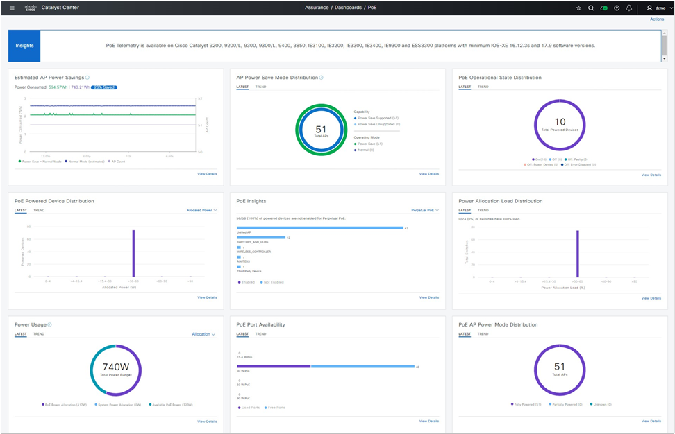
Cisco Catalyst Center PoE Analytics dashboard
Table 7. Elements of the Cisco Catalyst Center PoE Analytics dashboard
| Dashboard element |
Description |
| PoE Operational State Distribution |
Displays the number of PoE-capable devices in your network. This color-coded chart provides the count of devices based on whether they are being supplied with PoE or not. For each device that is not being supplied with PoE, it displays the reason why, so you can further analyze and troubleshoot power delivery issues. |
| PoE Powered Device Distribution |
In this chart, you can view the distribution of the devices currently using PoE for certain criteria, including allocated power and PD class. The chart enables you to drill down and answer questions like how many devices are consuming 90W of power. |
| PoE Insights |
This chart shows the percentage of the devices currently using PoE that are configured to support PoE technologies or comply with IEEE standards. With this analysis, you can view, for instance, how many devices are running Perpetual PoE. You can also turn on various PoE service levels within switches right from this dashboard. Availability of this information helps ensure that all critical PDs are protected and are functioning correctly or will retain power when the powering switch reboots. |
| Power Allocation Load Distribution |
In this chart, you can view the distribution of switches based on their power load for PoE, such as power load on the switching infrastructure for a certain site or building. It can help you identify switches with free ports and available power for placing new PDs. Further details about switches, such as their CPU usage, temperature, and power budget, can also be viewed. You can also use Catalyst Center’s ability to report, troubleshoot, and rectify any issues it finds with PoE delivery right from the dashboard. |
| Power Usage |
This chart shows you the total power consumption and allocated power by devices currently using PoE. With this information you can determine how much power budget you have available, in the system as a whole and in each PSE, so you can plan your deployment. |
| PoE Port Availability |
This chart provides details on the availability of switch ports based on their power load for PoE. This information can help in identifying PSEs that have free ports to which new PDs can be attached. |
| AP Power Save Mode Distribution |
This chart shows the number of Wi-Fi Access Points (APs) in Power Save mode vs. Normal mode. It also shows, out of the APs in normal mode, how many support Power Save mode. This information can help you save power by placing APs that may not be in use in Power Save mode. |
| AP Power Savings |
The information displayed shows how much power is being conserved by placing Wi-Fi APs in Power Save mode when not in use. |
| PoE AP Power Mode Distribution |
Shows the distribution of fully or partially powered Wi-Fi APs. This information can help you detect any gaps in Wi-Fi coverage due to PoE issues, troubleshoot, and restore coverage quickly. |
More details and troubleshooting information can be found in Cisco Catalyst Center’s Assurance screens using Device 360. For more information on this feature, please refer to the Cisco Catalyst Center documentation.
Overall, PoE is useful in industrial environments due to its simplicity, flexibility, cost savings, remote management capabilities, reliability, and safety features. But deploying it at scale requires proper planning, selection of appropriate equipment, and adherence to industry standards.
Check out the Cisco industrial switching portfolio, which offers a variety of PoE options suitable for deployment outdoors and in harsh environments. To quickly identify the right Cisco switch for your needs, use our switch selector.
For specific questions, please schedule a free, no obligation, consult with a Cisco industrial switching expert.