

Cisco C9550 Series Smart Switches
Fixed core and aggregation switches for AI-ready networks with integrated security and up to 400G uplinks.
Cisco C9610 Series Smart Switches
Powerful new modular smart switches for the core of the network, purpose-built to power, secure, and simplify the network for AI
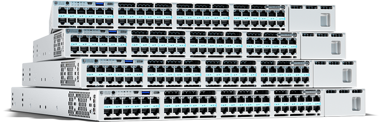
Cisco Catalyst 9500 Series Switches
Fixed switches for enterprise-class midsize and large campus-core networks
Cisco Catalyst 9600 Series Switches
Modular switches for enterprise-class midsize and large campus-core networks
Cisco Nexus 9000 Series Switches
Cloud-scale data center switches that are built for cloud connectivity and flexible design
Cisco Nexus 3550 Series
Ultra-low-latency platforms, switches, and components built for field-programmable gate array (FPGA) programming
Cisco Nexus 3000 Series Switches
Low-latency, high-density switches for general deployments and high-performance computing
Cisco MDS 9000 Series solutions
Storage area networking solutions built for optimized cloud, application, and big-data performance
Cisco N9300 Series Smart switches
Cisco smart switch with Cisco Hypershield is our platform play that integrates networking with security services.
Cisco embedded series
Ultracompact form factor designed for integrating into custom-built mission-critical devices
Cisco DIN rail industrial switches
Our DIN rail industrial switches deliver low-jitter, high-bandwidth connectivity with integrated security and Power over Ethernet (PoE). They also bridge the gap between OT and IT and enable the smooth operation of industrial AI applications.
Cisco IP66/IP67-rated industrial switches
Built for extreme environments, our IP66/IP67-rated industrial switches offer robust protection from dust and liquids, provide PoE, feature both fiber and copper ports, and are available in compact sizes for use in tight spaces.
Cisco rack-mount industrial switches
Our rack-mount industrial switches provide versatile connectivity with PoE, high-speed ports, stacking capabilities, and built-in security. These attributes make them ideal for access, distribution, or aggregation across diverse industrial deployments.
Cisco embedded industrial switches
Our compact cards simplify integration into your industrial machines and custom-built mission-critical devices.
Cisco Catalyst 9200CX Compact Switches
Optimized for smart buildings and fiber-to-the-office (FTTO) networks while offering enterprise-class security, management, and reliability
Cisco Meraki MS120 Series
Low power consumption, quiet acoustic design, and shallow rack depth options, enabling deployment flexibility in wiring closets as well as in offices and classrooms
Cisco Catalyst 1300 Series Managed Switches
Easy-to-manage, enterprise-grade switches that provide excellent performance and advanced security needed for small and medium-sized businesses at an affordable price
Cisco Catalyst 1200 Series Switches
Easy-to-manage, budget-friendly, enterprise-grade switches that provide the performance and security needed for the small and medium business network
Cisco Meraki MS130 Series
Versatile, cost-effective cloud-managed mGig switch designed to meet the diverse connectivity and security needs of branch and campus deployments.
Cisco Business 110 Series Switches
Affordable entry-level unmanaged switches with plug-and-play capability and Gigabit Ethernet for a seamless digital transformation.
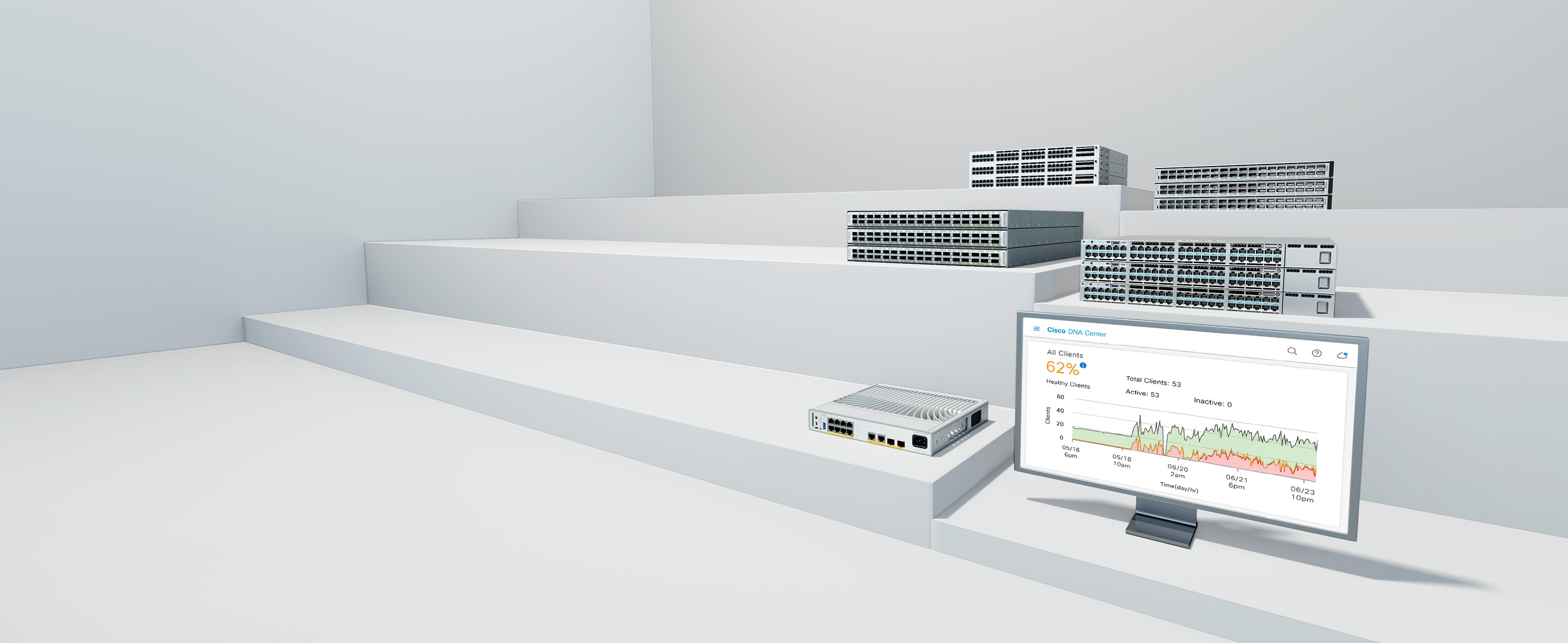
Cisco Catalyst Center
Get better performance and spend less time managing your network.
Cisco Meraki dashboard
Cloud monitoring for Catalyst switching is now available on the Meraki cloud management network platform.

Explore switching solutions
Get the guidance that you need
Cisco Success Tracks
Accelerate IT value
Optimize the value of your switching software for faster results, with digital insights and services expertise.
Lifecycle Services
Move your business forward
Build modern IT environments and accelerate agility with analytics-driven advisory services.