Cisco Unified Border Element (CUBE) Management and Manageability Specification
Available Languages
Table of Contents
1 Product/Feature......................................................................................................................... 3
1.1 Overview/Description............................................................................................................ 3
2 Embedded Management............................................................................................................ 5
2.1 CLI—Provisioning................................................................................................................... 5
2.1.1 Global CUBE CLI........................................................................................................... 6
2.1.2 SIP CLI......................................................................................................................... 7
2.1.3 H.323 CLI...................................................................................................................... 7
2.1.4 Dial-Peer CLI................................................................................................................ 8
2.1.5 Security Features CLI.................................................................................................... 8
2.2 CLI—Status............................................................................................................................ 9
2.2.1 SIP Trunk Status........................................................................................................... 9
2.2.2 Call Admission Control................................................................................................ 10
2.3 Protocol Monitoring............................................................................................................. 11
2.3.1 SIP Resource Availability............................................................................................. 11
2.4 SNMP Monitoring................................................................................................................ 12
2.4.1 Router and Interface Health....................................................................................... 12
2.4.2 SIP Trunk Status......................................................................................................... 13
2.4.3 Call Traffic Statistics.................................................................................................... 13
2.4.3.1 Real-Time Trunk Utilization............................................................................. 15
2.4.3.2 Historical Trunk Utilization.............................................................................. 17
2.4.3.3 Call Arrival Rate............................................................................................... 17
2.4.3.4 Call Success/Failure Statistics........................................................................... 17
2.4.3.5 Transcoding Session Capacity and DSP Utilization......................................... 20
2.4.3.6 MTP Session Capacity and DSP Utilization..................................................... 21
2.4.4 Licensing and Call Admission Control........................................................................... 22
2.4.5 Voice Quality MIBs..................................................................................................... 22
2.5 SNMP Traps......................................................................................................................... 23
2.6 Syslog Messages.................................................................................................................. 23
2.7 Embedded Event Manager (EEM)......................................................................................... 25
2.7.1 SIP Trunk Status......................................................................................................... 25
2.8 IP SLA.................................................................................................................................. 27
2.9 NetFlow............................................................................................................................... 27
3 Supported Management Applications....................................................................................... 29
4 Management Recommendations.............................................................................................. 31
4.1 Provisioning Recommendations............................................................................................ 31
4.1.1 Command Line (CLI)................................................................................................... 31
4.1.2 Graphical (GIU).......................................................................................................... 31
4.2 SIP Trunk Security Recommendations................................................................................... 33
4.2.1 Service Provider (SP) SIP Trunk Security...................................................................... 34
4.2.2 Toll Fraud Security...................................................................................................... 36
4.2.3 New Security Operation in Cisco IOS 15.1.2T................................................................ 36
4.3 Monitoring Recommendations............................................................................................. 37
4.4 Troubleshooting Recommendations..................................................................................... 38
4.4.1 General..................................................................................................................... 38
4.4.2 High-Traffic-Volume Troubleshooting (PCD)................................................................ 40
4.4.3 SIP Ladder Diagrams................................................................................................... 41
5 Glossary.................................................................................................................................. 43
6 How to buy............................................................................................................................... 44
7 References............................................................................................................................... 45
List of Tables
Table 1. Operations Phase and Management Capabilities........................................................................................... 5
Table 2. CISCO-PROCESS-MIB........................................................................................................................................ 13
Table 3. CISCO-MEMORY-POOL-MIB.............................................................................................................................. 13
Table 4. IF-MIB...................................................................................................................................................................... 13
Table 5. CISCO IOS MIBs that Contain Active Call Information.................................................................................. 14
Table 6. CISCO IOS MIBs that Contain Historical Call Information............................................................................ 14
Table 7. Real-Time Trunk Utilization: DIAL-CONTROL-MIB........................................................................................ 15
Table 8. Real-Time Trunk Utilization: CISCO-VOICE-DIAL-CONTROL-MIB............................................................. 15
Table 9. CISCO-VOICE-DIAL-CONTROL-MIB cvCallVolume Information............................................................... 16
Table 10. Historical Trunk Utilization MIB Information.................................................................................................... 17
Table 11. Call Arrival Rate MIB Information...................................................................................................................... 17
Table 12. Call Arrival Rate: CISCO-VOICE-DIAL-CONTROL-MIB................................................................................. 17
Table 13. Call Success/Failure MIB Information.............................................................................................................. 17
Table 14. CISCO-SIP-UA-MIB MIB Fields for 4xx, 5xx and 6xx SIP Responses........................................................ 18
Table 15. Transcoding Session Capacity and DSP Utilization MIB Information........................................................ 20
Table 16. Transcoding Session Capacity and DSP Utilization MIB Information........................................................ 21
Table 17. Voice Quality: CISCO-VOICE-DIAL-CONTROL-MIB...................................................................................... 23
Table 18. Voice Quality: RTTMON MIBs............................................................................................................................. 23
Table 19. Syslog Error Message Severity Levels............................................................................................................. 24
Table 20. Cisco IOS IP SLAs Operations and Applications............................................................................................ 27
Table 21. Supported Management Applications.............................................................................................................. 29
Table 22. Key “show” Commands on Cisco UBE............................................................................................................ 37
Table 23. Key “debug” Commands on Cisco UBE.......................................................................................................... 39
This Cisco Unified Border Element (Cisco UBE) Manageability Document contains information about the Simple Network Management Protocol (SNMP) MIBs, critical system log (syslog) messages and general Cisco IOS commands for monitoring and troubleshooting a Cisco UBE deployment. Cisco UBE is a Cisco IOS feature set supported on the Integrated Services Router (ISR) and Aggregation Services Routers (ASR) series platforms.
Cisco UBE is an integrated Cisco IOS enterprise session border controller (SBC) feature set facilitating simple and cost-effective connectivity between independent unified communications, voice over IP (VoIP), and video networks. Typical connectivity deployments where Cisco UBE is used include:
● Connect Cisco Unified Communication Manager (CUCM) enterprises to service provider SIP trunks
● Connect 3rd party IP-PBX enterprises to service provider SIP trunks
● Connect H.323 and SIP voice and video applications within the enterprise
● Connect H.323 video over the Internet into the enterprise
● Connect business-to-business TelePresence sessions between enterprises
Session border controllers (SBCs), such as Cisco UBE, offer unified communications network interoperability features such as:
● Session Management: Offers real-time session management at the network border, such as call admission control, dial-plan interpretation and routing, SLA monitoring, QoS policy marking, etc.
● Interworking: Offers feature to interconnect networks with different protocols or capabilities, such as H.323-SIP interworking, SIP normalization, DTMF type conversion, payload type conversion, IPv4-IPv6 interworking, transcoding and transrating, etc.
● Demarcation: Allows a single point of troubleshooting for SIP trunks and voice quality issues. Offers features such topology hiding, statistics and billing (call detail records, or CDR) at the border of the network.
● Security: Offers a security enforcement point at the network border through features such as SIP registration, SIP port protection, hostname validation, authentication and encryption features, etc.
Four aspects of Cisco UBE Manageability are addressed in this document:
1. Image, Configuration and License Management: General Cisco IOS router tools and methods are used for this. Cisco UBE licensing is in effect, but is only enforced for Gatekeeper configurations (as of 12.4.20T) and not yet for Cisco UBE configurations. When deploying any Unified Communications feature, including Cisco UBE, on and ISR G2 platform, the UC Technology Package is required. The licensing for this package is enforced.
See Cisco IOS Software Activation for more details.
2. Provisioning: General Cisco IOS router provisioning using the command line interface (CLI) is supported.
Support by management provisioning tools such as Cisco Configuration Professional (CCP). CCP 2.3 introduces support for Cisco UBE provisioning.
Cisco UBE provisioning includes the following elements:
● General router attributes
◦ Routing protocols, router interfaces, access lists, DNS connectivity, NTP (clock settings), QoS policies, SNMP connectivity, AAA/RADIUS connectivity, security features, etc.
● Global Cisco UBE attributes
◦ Turn on Cisco UBE as a router functions and specify the protocols that should be handled
◦ DSP hardware configuration and attributes (if present)
● SIP provisioning
◦ Global SIP parameters and attributes
◦ SIP header manipulation
◦ Dial-peers for SIP call sources and destinations
◦ SIP User Agent parameters and attributes
● H.323 provisioning
◦ Global H.323 parameters and attributes
◦ Dial-peers for H.323 call sources and destinations
● Dial-Plan provisioning
◦ Dial-peers, translation rules and digit manipulation features for interpreting the dial plan and routing calls as desired
3. Monitoring: General Cisco IOS router monitoring using CLI, syslog and SNMP are supported.
Cisco UBE supports most of the general Cisco IOS unified communications SNMP MIBs as well as several OIDs (object identifiers) developed specifically for Cisco UBE use cases.
Cisco UBE monitoring includes the following elements:
● Router Inventory and Health: CPU, memory, flash, modules, software image and release, etc.
● Interface Health: General IOS router interfaces, status and packet traffic statistics.
● SIP Trunk Status: Up or Down status of a SIP trunk to a service provider or application
● Call Traffic Statistics (Calls, Sessions, Capacity Planning, Errors):
◦ Trunk utilization and H.323/SIP Session Capacity
◦ Call arrival rate
◦ Call success/failure statistics
◦ SIP retries statistics
◦ Transcoding Session Capacity and DSP Utilization
◦ Media Termination Point (MTP) Session Capacity
● Licensing and Call Admission Control
● Resource Availability: Statistics and feedback to upstream call agents and load balancers
● Voice Quality: Statistics on packet loss, delay and jitter that can be calculated into metrics such as ICPIF, MOS and R-factor scores
● Billing: CDR, call patterns, toll fraud monitoring
4. Troubleshooting: General Cisco IOS router troubleshooting using CLI show and debug commands, as well as packet capture methods, are supported.
Cisco UBE supports most of the general Cisco IOS unified communications show and debug commands as well as several commands, and extensions to existing commands, developed specifically for Cisco UBE use cases, such as Per Call Debugging (PCD).
Table 1 provides an overview of Cisco UBE management capabilities that can be used during different operations phases.
Table 1. Operations Phase and Management Capabilities
| Operations Phase |
Management Capability |
| Staging/Configuration |
● Cisco IOS CLI
● Cisco Configuration Engine (CCE)
● Configuration examples at
www.cisco.com/go/interoperability > Cisco Unified Border Element/SIP Trunking Solutions
● Cisco Configuration Professional 2.3 or later
|
| Installation/Provisioning |
● Cisco IOS CLI
● Configuration examples at
www.cisco.com/go/interoperability > Cisco Unified Border Element/SIP Trunking Solutions
●
Cisco Configuration Professional (CCP) 2.3 or later
|
| Change Management/Archiving |
● Cisco IOS CLI
|
| Fault Monitoring/Management |
● Cisco IOS CLI
● Any SNMP-based management system
|
| Performance Monitoring/Management |
● Cisco IOS CLI (show and debug commands)
● Cisco UBE CDR
● Any SNMP-based management system
|
| Troubleshooting |
● Cisco IOS CLI (show and debug commands)
● Cisco IOS syslog
● Wireshark (open source application)
|
Key embedded management capabilities of the Cisco IOS router where Cisco UBE is deployed are covered in this section. This includes:
● CLI
● SNMP
● Syslog
● IP SLA
● EEM
● NetFlow
This section summarizes the key or common Cisco UBE CLI used to provision basic system functionality. Most specialized Cisco UBE features and deployments have additional CLI to turn on specific features. General Cisco IOS router configuration is assumed known and is not covered here.
Additional in-depth Cisco UBE configuration resources include:
● Cisco UBE IOS configuration is fully documented at: https://www.cisco.com/c/en/us/products/unified-communications/unified-border-element/index.html> Configure > Configuration Guides > Cisco Unified Border Element Configuration Guide.
● Cisco UBE IOS configuration is fully documented at: https://www.cisco.com/c/en/us/products/unified-communications/unified-border-element/index.html > Configure > Configuration Guides > Cisco Unified Border Element Configuration Guide.
● Cisco UBE CLI commands are documented as part of the general Cisco IOS command reference documentation on Cisco.com
● Cisco UBE configuration examples are given at https://www.cisco.com/c/en/us/products/unified-communications/unified-border-element/index.html > Configure > Configuration Guides > Configuration Examples and TechNotes
● Cisco UBE interoperability configuration guides with service provider SIP trunks and 3rd party IP-PBXs are given at www.cisco.com/go/interoperability > Cisco Unified Border Element (CUBE)/SIP Trunking Solutions
Note: Please refer to the general Cisco IOS command references on Cisco.com for a full explanation of command options and syntax, only abbreviated examples are given in the following sections.
Several attributes of CUBE are configured at the global level of the router. This includes generic capabilities, as well as global SIP and H.323 capabilities.
Basic routing, connectivity and access lists are required as pre-requisite router configuration for CUBE. Additional generic router capabilities such as DHCP, QoS or firewall are optional.
Enable CUBE (all platforms):
Cisco UBE is being deployed on a Cisco IOS router when one of the following commands is present:
voice service voip
allow-connections h323 to h323
allow-connections h323 to sip
allow-connections sip to h323
allow-connections sip to sip
Enable CUBE (required on ISR G2):
Cisco UBE is turned on for an ISR G2 platform with the following command:
voice service voip
mode border-element
Fax:
Fax configuration on Cisco UBE uses the same CLI as fax control commands for Cisco IOS PSTN gateways. This includes both global and dial-peer commands.
More information can be found in the Cisco IOS Fax, Modem, and Text Support over IP Configuration Guide.
Call Admission Control (CAC):
Cisco UBE supports global or interface-level CAC based on call count, CPU or memory use by using the following CLI:
call threshold global
call threshold interface
call treatment on
Cisco UBE can detect (and alter behavior) spikes in call arrival rate (useful for SIP DOS protection) by using the following CLI:
call spike
Cisco UBE supports destination-specific limits on call counts by using the following CLI:
dial-peer voice x voip
max-connection
Transcoding:
Cisco UBE can use DSPs to provide transcoding and transrating services. This configuration is covered in detail in the Cisco UBE configuration examples given at https://www.cisco.com/c/en/us/products/unified-communications/unified-border-element/index.html > Configure > Configuration Guides > Configuration Examples and TechNotes > Unified Border Element Transcoding Configuration Example.
Several SIP attributes of Cisco UBE are configured at the global level of the router and applies to all SIP communications. Many Cisco UBE features have both global and dial-peer CLI so that they can easily be turned on globally if the function is needed on all calls or turned on/off per call destination if more granular or policy control of call handling is needed.
voice service voip
sip
address-hiding
bind control
bind media
session transport
rel1xx
header-passing
midcall-signaling passthrough
sip-ua
authentication
credentials
registrar
sip-server
retry invite
retry register
timers connect
Several H.323 attributes of Cisco UBE are configured at the global level of the router and applies to all H.323 communications. Many Cisco UBE features have both global and dial-peer CLI so that they can easily be turned on globally if the function is needed on all calls or turned on/off per call destination if more granular or policy control of call handling is needed.
H.323-H.323:
voice service voip
no supplementary-service h450.2 ! Disable call transfer with H.450
no supplementary-service h450.3 ! Disable call forward with H.450
no supplementary-service h450.7
no supplementary-service h450.12 ! Hidden CLI
supplementary-service media-renegotiate ! Enables media renegotiation in case
! of Refer to ECS
supplementary-service ringback h225-info ! Enables Ringback
h323
emptycapability ! Enables supplementary services using ECS
h245 passthru tcsnonstd-passthru ! Interop with CUCM to pass-through
! non-standard parameters
h225 connect-passthrough ! Required for H323-H323 calls with CUCM
Additional commands for H.323-H.323:
voice service voip
address-hiding
allow-connections h323 to h323
Additional commands for H.323-SIP:
voice service voip
address-hiding
allow-connections h323 to sip
allow-connections sip to h323
Cisco UBE dial-plan interpretation and call routing is implemented using VoIP dial-peers and the configuration is very similar to that of a Cisco IOS PSTN gateway. Translation rules and digit manipulation features are supported on both deployments.
Please refer to the Cisco.com Cisco IOS Dial Peer Configuration on Voice Gateway Routers configuration guide for details of available dial plan implementation commands.
H.323 is the default protocol for a dial-peer in Cisco IOS. To enable SIP as the protocol, use the following command:
dial-peer voice x voip
session protocol sipv2
As of Cisco UBE 8.5 (IOS 15.1.2T), the source IP address used in SIP messaging can be controlled per dial-peer by using the following CLI:
dial-peer voice x voip
session protocol sipv2
voice-class sip bind control
voice-class sip bind media
Some Cisco UBE-specific security features, such as topology hiding and protocol stack protection (detecting malformed and rogue packets) are enabled and active by default. Many other features are not enabled by default and require CLI to mitigate against targeted attacks or security breaches. Like any other network and router device, Cisco UBE should be locked down against security attacks. Please see the later section on “Security Recommendations” for guidelines on feature to turn on.
SIP trunk status is an important element of CUBE monitoring. SIP Trunk status can be monitored by configuring an out-of-dialog (OOD) SIP Options PING as a keepalive mechanism on the dial-peer(s) pointing towards the SIP Trunk, using the CLI example below.
dial-peer voice 100 voip
destination-pattern .T
voice-class sip options-keepalive up-interval 100 down-interval 50 retry 6
session protocol sipv2
session target ipv4:x.x.x.x
When calls to the SIP trunk are successful, the dial-peer is in “active” state. If SIP PING timeouts occur, the dial-peer changes to “busyout” status. Calls to the dial-peer during “busyout” will be rejected immediately to the originator for call rerouting.
● CUBE 1.3 (Cisco IOS 15.0.1M) returns an unconfigurable SIP “404 Not Found” error code
● CUBE 1.4 (15.1.1T) or later allows a configurable SIP error code in the 400-699 range. The default is “503 Service Unavailable”
Dial-peer state changes are as follows:
● Dial-peer is marked as “active” when a valid response to an Options PING is received
● Dial-peer is marked as “busyout” when no response to an Options PING is received
● Dial-peer status changes from “active” to “busyout” when:
◦ A “503 Service Unavailable” response is received
◦ No response is received, i.e. request timeout (configurable number of retries)
◦ A “505 Version not supported” response is received
● Dial-peer status changes from “busyout” to “active” after a configurable number of consecutive positive responses (i.e. anything except 503, 505 and t/o)
● On router reboot, all dial-peers start in the “active” state
The CLI to configure a SIP OOD Options PING is:
voice service voip
sip
error-code-override options-keepalive failure 500
dial-peer voice 10 voip
voice-class sip error-code-override options-keepalive failure 500
The dial-peer status based on the SIP OOD Options PING can be displayed with the following “show” commands:
router# show dial-peer voice summary
AD PRE PASS OUT
TAG TYPE MIN OPER PREFIX DEST-PATTERN FER THRU SESS-TARGET STAT PORT KEEPALIVE
1 voip up up 1000 0 syst ipv4:x.x.x.10 active
2 voip up up 2000 0 syst ipv4:x.x.x.11 busyout
3 voip up up 3000 0 syst ipv4:x.x.x.12
router# show dial-peer voice | include options
voice class sip options-keepalive up-interval 100 down-interval 50 retry 6
voice class sip options-keepalive dial-peer action = active,
voice class sip options-keepalive up-interval 100 down-interval 50 retry 6
voice class sip options-keepalive dial-peer action = busyout,
In CUBE releases older than CUBE 1.3 (15.0.1M), or in addition to the layer 7 SIP monitoring described above, a layer 3 connectivity monitoring can be done using an ICMP ping. The following CLI can be used to enable this feature:
dial-peer voice 10 voip
destination-pattern .T
monitor probe icmp-ping x.x.x.x
session protocol sipv2
session target ipv4:x.x.x.x
Call rejections due to CAC threshold being met or exceeded can be seen by using the following show commands:
show call spike status
show call threshold status
show call admission statistics
show call treatment stats
Some statistics or traffic information are embedded within the SIP or H.323 call control protocol. These are covered in this section.
Statistics and feedback to upstream call agents and load balancers are provided by Cisco UBE so that these network elements can adjust their call routing and load balancing algorithms based on the load experienced by the session border controller (Cisco UBE). One such method is the Resource Availability Indicator (RAI), available in both H.323 and SIP.
2.3.1 SIP Resource Availability
RAI for SIP is implemented as of CUBE 8.5 (Cisco IOS release 15.1.2T). Cisco UBE resources that can be monitored using this method include:
● System
● CPU
● Memory
● DSP
The method uses an Out-of-Dialog SIP OPTIONS PING message Cisco UBE to the upstream call agent or load balancer. The SIP RAI notification can be initiated by any of these methods:
● Unsolicited (based on static Cisco UBE configuration)
◦ Periodically based on a timer configuration
◦ Notification when a threshold value (low/high water mark configuration) is crossed for a given resource
● Solicited (polled, or query/response)
◦ An SIP application can request RAI information
The following is a sample configuration for unsolicited (based on configuration) periodic RAI reporting.
voice class resource-group 1
resource cpu 1-min-avg
resource dsp
resource mem total-mem
periodic-report interval 30
!
sip-ua
rai target ipv4:9.13.40.83 resource-group 1
The following is a sample configuration for unsolicited (based on configuration) threshold-based RAI reporting.
voice class resource-group 2
resource cpu 1-min-avg threshold high 50 low 30
resource dsp threshold high 50 low 30
resource mem total-mem threshold high 50 low 30
!
sip-ua
rai target ipv4:9.13.40.83 resource-group 2
A SIP application can also poll for RAI status. In this case it sends an SIP OPTIONS PING to Cisco UBE which responds with the resource information on a 200-OK message. For this, the following configuration is needed:
An example of the configuration of the upstream entity to report the RAI to is as follows:
sip-ua
rai target ipv4:x.x.x.x resource-group x
Simple Network Management Protocol (SNMP) is based on the manager/agent model consisting of an SNMP manager, an SNMP agent, a database of management information, managed SNMP devices and the network protocol. The SNMP manager provides the interface between the human network manager and the management system. The SNMP agent provides the interface between the manager and the physical device being managed.
An SNMP-managed network consists of the following:
● Managed Device: A network node that contains an SNMP agent that resides on a managed network. Managed devices collect and store management information and use SNMP to make this information available to the NMS. Managed devices, sometimes called network elements, can include routers and access servers, switches and bridges, hubs, computer hosts, and printers.
● Agent: A network management software module that resides in a managed device. An agent has local knowledge of management information and translates that information into a form compatible with SNMP.
● NMS: Executes applications that monitor and control managed devices. NMSs provide most of the processing and memory resources required for network management. Every managed network must have one or more NMS.
The SNMP agent exchanges network management information with the SNMP manager software that is running on a network management system (NMS). The agent responds to requests for information and actions from the managed device (in this case the Cisco UBE router). The agent controls access to the agent’s MIB, the collection of objects that can be viewed or changed by the SNMP manager. By polling managed devices, an SNMP manager collects information on network connectivity, activity, and events.
Cisco UBE monitoring via SNMP includes the following capabilities:
● Router and Interface Health
● Call Traffic Reports
◦ Trunk utilization and H.323/SIP Session Capacity
◦ Call arrival rate
◦ Call success/failure statistics
◦ SIP retries statistics
◦ Transcoding Session Capacity and DSP Utilization
◦ MTP Session Capacity
● Licensing and Call Admission Control
● Voice Quality: Statistics on packet loss, delay and jitter that can be calculated into metrics such as ICPIF, MOS and R-factor scores
2.4.1 Router and Interface Health
These MIBs/OIDs allow you to monitor the physical chassis, interface connectivity, CPU and memory.
● Router Inventory and Health: CPU, memory, flash, modules, software image and release, etc.
● Interface Health: General IOS router interfaces, status and packet traffic statistics.
Critical router functions, like routing protocol processing and process packet switching, are handled in memory and share the CPU. Thus, if CPU utilization is very high, it is possible that a routing update cannot be handled or packets are dropped. The CISCO-PROCESS-MIB reports the percentage of the processor in use over a five-minute average.
| OID |
OID# |
New/Changed |
Platform |
Use/Operation |
| cpmCPUTotal5minRev |
1.3.6.1.4.1.9.9.109.1.1.1.1.8 |
Original IOS |
All |
Health |
Memory use can be monitored using the CISCO-MEMORY-POOL-MIB.
Table 3. CISCO-MEMORY-POOL-MIB
| OID |
OID# |
New/Changed |
Platform |
Use/Operation |
| ciscoMemoryPoolEntry |
1.3.6.1.4.1.9.9.48.1.1.1 |
Baseline |
All |
Health Monitoring |
The status of physical interfaces on the router platform can be monitored using the IF-MIB.
| OID |
OID# |
New/Changed |
Platform |
Use/Operation |
| IfEntry |
1.3.6.1.2.1.2.2.1 |
Baseline |
All |
Fault Monitoring |
SIP trunk status is an important element of CUBE monitoring. This status is not currently available via SNMP (only via CLI as covered in the previous section).
A key element of CUBE monitoring is call traffic reports, both for the volume of calls over time, or for monitoring of call arrival rates. This is useful for various business purposes, including:
● Trunk utilization, both real-time and historical
● Capacity planning
● Troubleshooting
● Highlighting errors occurring in call routing or call handling that may indicate a network outage, dial-plan deficiencies, or perhaps an architectural call flow that is not implemented correctly
● Detecting call spikes, caused by both normal (an uptick in traffic due to an advertisement or other business event) and malicious (a SIP DOS attack) traffic patterns
CUBE call traffic reports can be provided by information in several SNMP MIBs, some of which have been available historically in all Cisco IOS releases, and others specifically introduced with CUBE 1.4 to aid in traffic reporting. For best results, using CUBE 1.4 or later is recommended.
● Trunk utilization and H.323/SIP session capacity statistics
● Call arrival rate statistics
● Call success/failure statistics
● SIP error and timeout/retry statistics
● DSP utilization and transcoding session capacity
● MTP utilization and session capacity
Cisco IOS voice/video call SNMP information is generally kept in the set of MIBs given below. These MIBs are used for TDM voice calls as well as VoIP, VoFR and VoATM calls. Some OIDs are only populated for certain types of calls. On the Cisco ISR platforms, these MIBs have been supported for a long time, for Cisco UBE on the Cisco ASR 1000 Series platforms, they are supported as of release 3.1.0.
● DIAL-CONTROL-MIB
● CISCO-DIAL-CONTROL-MIB
● CISCO-VOICE-DIAL-CONTROL-MIB
● CISCO-VOICE-COMMON-DIAL-CONTROL-MIB
● CISCO-CALL-HISTORY-MIB (this MIB is only populated for ISDN calls on TDM voice gateways and therefore does not apply to Cisco UBE and will not be discussed further here.)
These MIBs generally provide information on:
● Currently Active Calls: Real-time statistics of call activity
● Call History: Historical statistics after calls have disconnected (similar to CDR)
Table 5. CISCO IOS MIBs that Contain Active Call Information
| MIB |
OID |
Table Name |
Number of Entries per Call |
| DIAL-CONTROL-MIB |
1.3.6.1.2.1.10.21 |
callActiveTable |
2 |
| CISCO-VOICE-COMMON-DIAL-CONTROL-MIB |
1.3.6.1.4.1.9.10.55 |
cvCommonDcCallActiveTable |
2 |
| CISCO-VOICE-DIAL-CONTROL-MIB |
1.3.6.1.4.1.9.9.63 |
cvCallActiveTable |
0 (Used for TDM GW calls only) |
| CISCO-VOICE-DIAL-CONTROL-MIB |
1.3.6.1.4.1.9.9.63 |
cvVoIPCallActiveTable |
2 |
Table 6. CISCO IOS MIBs that Contain Historical Call Information
| MIB |
OID |
Call History |
Number of Entries per Call |
| DIAL-CONTROL-MIB |
1.3.6.1.2.1.10.21 |
callHistoryTable |
Not implemented, do not use |
| CISCO-DIAL-CONTROL-MIB |
1.3.6.1.4.1.9.10.25 |
cCallHistory |
2 |
| CISCO-VOICE-COMMON-DIAL-CONTROL-MIB |
1.3.6.1.4.1.9.10.55 |
cvCommonDcCallHistoryTable |
2 |
| CISCO-VOICE-DIAL-CONTROL-MIB |
1.3.6.1.4.1.9.9.63 |
cvCallHistoryTable |
0 (Used for TDM GW calls only) |
The following “show” commands provide information on active voice, video and fax calls in the system:
sh call active ?
fax show all active calls for fax store & forward
media show all active calls for media
video show all active calls for video
voice show all active calls for voice
!
sh call active video ?
brief show brief version of active video calls
compact show compact version of active video calls
id show only call with specified id
!
sh call active fax ?
brief show brief version of active fax calls
compact show compact version of active fax calls
2.4.3.1 Real-Time Trunk Utilization
Various aspects of real-time Trunk Utilization statistics on currently active calls are available from the MIBs and OIDs covered in this section.
When a callActiveTable (1.3.6.1.2.1.10.21.1.3.1) entry is created for a call, an associated cvCallActiveTable (1.3.6.1.4.1.9.9.63.1.3.1) and cvCommonDcCallActiveTable(1.3.6.1.4.1.9.10.55.1.1.1) entries are created. They are indexed by the callActiveSetupTime (1.3.6.1.2.1.10.21.1.3.1.1.1) and callActiveIndex (1.3.6.1.2.1.10.21.1.3.1.1.2) as defined in DIAL-CONTROL-MIB.
The DIAL-CONTROL-MIB provides:
● RFC-2128 information
● Monitoring of active calls on a particular dial peer
● Packet received/transmitted statistics for active calls
The usefulness of the DIAL-CONTROL-MIB entries (callActiveTransmitPackets, callActiveTransmitBytes, callActiveReceivePackets, callActiveReceiveBytes) is essentially for packet received and transmitted statistics. For most other call parameters, the information provided in the CISCO-VOICE-DIAL-CONTROL-MIB is most useful.
Table 7. Real-Time Trunk Utilization: DIAL-CONTROL-MIB
| OID |
OID# |
New/Changed |
Platform |
Use/Operation |
| dialCtlPeerStatsTable |
1.3.6.1.2.1.10.21.1.2.2 |
Baseline |
ISR G1, ISR G2, AS5x00, ASR |
Provides statistics on overall dial-peer use, indexed by dial-peer number. |
| callActiveTable |
1.3.6.1.2.1.10.21.1.3.1 |
Baseline |
ISR G1, ISR G2, AS5x00, ASR |
Provides packet statistics on active calls, indexed by callActiveSetupTime and callActiveIndex. |
The CISCO-VOICE-DIAL-CONTROL-MIB provides the number of active calls based on:
● Protocol (H.323 or SIP)
● Dial-Peer
● Interface
Table 8. Real-Time Trunk Utilization: CISCO-VOICE-DIAL-CONTROL-MIB
| OID |
OID# |
New/Changed |
Platform |
Use/Operation |
| cvVoIPCallActiveTable |
1.3.6.1.4.1.9.9.63.1.3.2 |
Baseline |
ISR G1, ISR G2, AS5x00, ASR |
Provides statistics on active VoIP calls, indexed by callActiveSetupTime and callActiveIndex. |
| cvCallVolume |
1.3.6.1.4.1.9.9.63.1.3.8 |
CUBE 1.4 |
ISR G1, ISR G2, AS5x00 |
Total, per-protocol, per-dial-peer and per-interface call active statistics. |
Total Trunk Utilization:
A snapshot summary of overall call active statistics on the platform is given by the cvCallVolConnTotalActiveConnections (1.3.6.1.4.1.9.9.63.1.3.8.2) OID.
More detailed information per call (packet statistics, VAD, SRTP, etc.) is given in the cvVoIPCallActiveEntry (1.3.6.1.4.1.9.9.63.1.3.2.1) OID.
Trunk Utilization by Protocol:
A snapshot of call active statistics per protocol is given by the cvCallVolConnEntry (1.3.6.1.4.1.9.9.63.1.3.8.1.1) OID. The cvCallVolConnIndex (1.3.6.1.4.1.9.9.63.1.3.8.1.1.1) defines the protocol type, H.323 = 1, SIP = 2. Therefore:
● H.323 (1) call statistics are in the CvCallVolConnActiveConnection.1 (1.3.6.1.4.1.9.9.63.1.3.8.1.1.2.1) OID
● SIP(2) call statistics are in the CvCallVolConnActiveConnection.2 (1.3.6.1.4.1.9.9.63.1.3.8.1.1.2.2) OID
Trunk Utilization by Dial-Peer:
A snapshot of call active statistics per dial-peer is given by the cvCallVolPeerEntry (1.3.6.1.4.1.9.9.63.1.3.8.4.1) OID. This table augments the dial-peer configuration table in the cvPeerCfgTable (1.3.6.1.4.1.9.9.63.1.2.1) OID, and uses the dial-peer tag as an index. Therefore:
● Incoming call statistics for dial-peer 200 are in the cvCallVolPeerIncomingCalls.200 (1.3.6.1.4.1.9.9.63.1.3.8.4.1.1.200) OID
● Outgoing call statistics for dial-peer 200 are in cvCallVolPeerOutgoingCalls.200 (1.3.6.1.4.1.9.9.63.1.3.8.4.1.2.200) OID
Trunk Utilization by Interface:
A snapshot of call active statistics per interface is given by the cvCallVolIfTableEntry (1.3.6.1.4.1.9.9.63.1.3.8.5.1) OID. This table is indexed by the interface number using the ifIndex (1.3.6.1.2.1.2.2.1.1) OID in the IF-MIB. Therefore:
● Incoming call statistics for interface 5 are in the cvCallVolMediaIncomingCalls.5 (1.3.6.1.4.1.9.9.63.1.3.8.5.1.1.5) OID
● Outgoing call statistics for interface 5 are in cvCallVolMediaOutgoingCalls.5 (1.3.6.1.4.1.9.9.63.1.3.8.5.1.2.5) OID
The cvCallVolume OID in the CISCO-VOICE-DIAL-CONTROL-MIB contains the following call volume information:
Table 9. CISCO-VOICE-DIAL-CONTROL-MIB cvCallVolume Information
| OID |
OID# |
Use/Operation |
| cvCallVolConnIndex |
1.3.6.1.4.1.9.9.63.1.3.8.1.1.1 |
Index to the cvCallVolConnTable. A value of 1 denotes H.323 calls, and 2 SIP calls. |
| cvCallVolConnActiveConnection |
1.3.6.1.4.1.9.9.63.1.3.8.1.1.2 |
Number of calls active of the type determined by cvCallVolConnIndex. |
| cvCallVolConnTotalActiveConnections |
1.3.6.1.4.1.9.9.63.1.3.8.2 |
Total number of active calls on the platform. |
| cvCallVolPeerIncomingCalls |
1.3.6.1.4.1.9.9.63.1.3.8.4.1.1 |
Number of active incoming calls for a dial-peer. |
| cvCallVolPeerOutgoingCalls |
1.3.6.1.4.1.9.9.63.1.3.8.4.1.2 |
Number of active outcoming calls for a dial-peer. |
| cvCallVolMediaIncomingCalls |
1.3.6.1.4.1.9.9.63.1.3.8.5.1.1 |
Number of active incoming calls for an interface. |
| cvCallVolMediaOutgoingCalls |
1.3.6.1.4.1.9.9.63.1.3.8.5.1.2 |
Number of active outgoing calls for an interface. |
2.4.3.2 Historical Trunk Utilization
Historical Trunk Utilization statistics on completed calls are available from the MIBs and OIDs covered in this section. Alternatively, you can also use the Real-time Trunk Utilization statistics in the previous section and store this info to provide your own aggregation and trending information. Up to 1200 call history records are stored in memory in a circular buffer.
Table 10. Historical Trunk Utilization MIB Information
| MIB |
OID |
OID# |
New/Changed |
Platform |
| CISCO-DIAL-CONTROL-MIB |
cCallHistoryTable |
1.3.6.1.4.1.9.10.25.1.4.3 |
Baseline |
ISR G1, ISR G2, AS5x00, ASR |
| CISCO-VOICE-DIAL-CONTROL-MIB |
cvVoIPCallHistoryTable |
1.3.6.1.4.1.9.9.63.1.4.2 |
Baseline |
ISR G1, ISR G2, AS5x00, ASR |
| CISCO-VOICE-COMMON-DIAL-CONTROL-MIB |
cvCommonDcCallHistory |
1.3.6.1.4.1.9.10.55.1.2.1 |
Baseline |
ISR G1, ISR G2, AS5x00, ASR |
Call arrival rate and call spikes can be monitored as of CUBE 1.4 (15.1.1T) or later using the CISCO-VOICE-DIAL-CONTROL-MIB MIB information covered in this section.
Table 11. Call Arrival Rate MIB Information
| OID |
OID# |
New/Changed |
Platform |
| cvCallRateMonitor |
1.3.6.1.4.1.9.9.63.1.3.11 |
CUBE 1.4 |
ISR G1, ISR G2, AS5x00 |
By default call rate information is not gathered and the MIB information is empty. To turn on call rate monitoring, use the cvCallRateMonitorEnable (1.3.6.1.4.1.9.9.63.1.3.11.1) OID and set the monitoring period with the cvCallRateMonitorTime (1.3.6.1.4.1.9.9.63.1.3.11.2) OID. There is no facility to turn monitoring on or off via CLI.
The cvCallRateMonitor OID in the CISCO-VOICE-DIAL-CONTROL-MIB contains the following call rate information.
Table 12. Call Arrival Rate: CISCO-VOICE-DIAL-CONTROL-MIB
| OID |
OID# |
Use/Operation |
| cvCallRateMonitorEnable |
1.3.6.1.4.1.9.9.63.1.3.11.1 |
A value of TRUE starts computation of call rate information. A value of FALSE turns it off. |
| cvCallRateMonitorTime |
1.3.6.1.4.1.9.9.63.1.3.11.2 |
Value can from 1 to 12—each value denotes a time unit of 5 seconds. That is, a value of 1 means 5 seconds, a value of 2 means 10 seconds, etc. |
| cvCallRate |
1.3.6.1.4.1.9.9.63.1.3.11.3 |
Number of calls connected during the last monitoring period duration. |
| cvCallRateHiWaterMark |
1.3.6.1.4.1.9.9.63.1.3.11.4 |
Peak value in any given cvCallRateMonitorTime duration if cvCallRateMonitorEnable is set to TRUE. |
2.4.3.4 Call Success/Failure Statistics
Successful and failed call counts can be monitored for trending or troubleshooting purposes using the MIB information covered in this section.
Table 13. Call Success/Failure MIB Information
| MIB |
OID |
OID# |
New/Changed |
Platform |
| DIAL-CONTROL-MIB |
dialCtlPeerStatsTable |
1.3.6.1.2.1.10.21.1.2.2 |
Baseline |
ISR G1, ISR G2, AS5x00, ASR |
| CISCO-SIP-UA-MIB |
cSipStats |
1.3.6.1.4.1.9.9.152.1.2 |
Baseline |
ISR G1, ISR G2, AS5x00, ASR |
The DIAL-CONTROL-MIB provides information per dial-peer for both H.323 and SIP using the following OIDs:
● Success
◦ dialCtlPeerStatsSuccessCalls (1.3.6.1.2.1.10.21.1.2.2.1.3)
◦ dialCtlPeerStatsAcceptCalls (1.3.6.1.2.1.10.21.1.2.2.1.5)
● Failure
◦ dialCtlPeerStatsFailCalls (1.3.6.1.2.1.10.21.1.2.2.1.4)
◦ dialCtlPeerStatsRefuseCalls (1.3.6.1.2.1.10.21.1.2.2.1.6)
The protocol that a call uses can be found by associating the dial-peer entry (dialCtlPeerStatsEntry, 1.3.6.1.2.1.10.21.1.2.2.1 OID) in the DIAL-CONTROL-MIB with the corresponding dial-peer entry (cvVoIPPeerCfgEntry, 1.3.6.1.4.1.9.9.63.1.2.3.1 OID) in the CISCO-VOICE-DIAL-CONTROL-MIB. The cvVoIPPeerCfgSessionProtocol (1.3.6.1.4.1.9.9.63.1.2.3.1.1) OID in the CISCO-VOICE-DIAL-CONTROL-MIB uses a value of “Cisco (2)” for H.323 and “sip (3)” for SIP.
The CISCO-SIP-UA-MIB provides information on SIP call success/failure using the following OIDs:
● Success
◦ cSipStatsSuccess (1.3.6.1.4.1.9.9.152.1.2.2)
◦ cSipStatsRedirect 1.3.6.1.4.1.9.9.152.1.2.3
● Failure
◦ cSipStatsErrClient 1.3.6.1.4.1.9.9.152.1.2.4 (4xx errors)
◦ cSipStatsErrServer 1.3.6.1.4.1.9.9.152.1.2.5 (5xx errors)
◦ cSipStatsGlobalFail 1.3.6.1.4.1.9.9.152.1.2.6 (6xx errors)
● Retry/Timeouts
◦ cSipStatsRetry 1.3.6.1.4.1.9.9.152.1.2.8 (retries/timeouts)
Table 14. CISCO-SIP-UA-MIB MIB Fields for 4xx, 5xx and 6xx SIP Responses
| OID |
OID# |
SIP 4xx Error |
| cSipStatsClientBadRequestIns |
1.3.6.1.4.1.9.9.152.1.2.4.1 |
400 |
| cSipStatsClientBadRequestOuts |
1.3.6.1.4.1.9.9.152.1.2.4.2 |
400 |
| cSipStatsClientUnauthorizedIns |
1.3.6.1.4.1.9.9.152.1.2.4.3 |
401 |
| cSipStatsClientUnauthorizedOuts |
1.3.6.1.4.1.9.9.152.1.2.4.4 |
401 |
| cSipStatsClientPaymentReqdIns |
1.3.6.1.4.1.9.9.152.1.2.4.5 |
402 |
| cSipStatsClientPaymentReqdOuts |
1.3.6.1.4.1.9.9.152.1.2.4.6 |
402 |
| cSipStatsClientForbiddenIns |
1.3.6.1.4.1.9.9.152.1.2.4.7 |
403 |
| cSipStatsClientForbiddenOuts |
1.3.6.1.4.1.9.9.152.1.2.4.8 |
403 |
| cSipStatsClientNotFoundIns |
1.3.6.1.4.1.9.9.152.1.2.4.9 |
404 |
| cSipStatsClientNotFoundOuts |
1.3.6.1.4.1.9.9.152.1.2.4.10 |
404 |
| cSipStatsClientMethNotAllowedIns |
1.3.6.1.4.1.9.9.152.1.2.4.11 |
405 |
| cSipStatsClientMethNotAllowedOuts |
1.3.6.1.4.1.9.9.152.1.2.4.12 |
405 |
| cSipStatsClientNotAcceptableIns |
1.3.6.1.4.1.9.9.152.1.2.4.13 |
406 |
| cSipStatsClientNotAcceptableOuts |
1.3.6.1.4.1.9.9.152.1.2.4.14 |
406 |
| cSipStatsClientProxyAuthReqdIns |
1.3.6.1.4.1.9.9.152.1.2.4.15 |
407 |
| cSipStatsClientProxyAuthReqdOuts |
1.3.6.1.4.1.9.9.152.1.2.4.16 |
407 |
| cSipStatsClientReqTimeoutIns |
1.3.6.1.4.1.9.9.152.1.2.4.17 |
408 |
| cSipStatsClientReqTimeoutOuts |
1.3.6.1.4.1.9.9.152.1.2.4.18 |
408 |
| cSipStatsClientConflictIns |
1.3.6.1.4.1.9.9.152.1.2.4.19 |
409 |
| cSipStatsClientConflictOuts |
1.3.6.1.4.1.9.9.152.1.2.4.20 |
409 |
| cSipStatsClientGoneIns |
1.3.6.1.4.1.9.9.152.1.2.4.21 |
410 |
| cSipStatsClientGoneOuts |
1.3.6.1.4.1.9.9.152.1.2.4.22 |
410 |
| cSipStatsClientLengthRequiredIns |
1.3.6.1.4.1.9.9.152.1.2.4.23 |
411 |
| cSipStatsClientLengthRequiredOuts |
1.3.6.1.4.1.9.9.152.1.2.4.24 |
411 |
| cSipStatsClientReqEntTooLargeIns |
1.3.6.1.4.1.9.9.152.1.2.4.25 |
413 |
| cSipStatsClientReqEntTooLargeOuts |
1.3.6.1.4.1.9.9.152.1.2.4.26 |
413 |
| cSipStatsClientReqURITooLargeIns |
1.3.6.1.4.1.9.9.152.1.2.4.27 |
414 |
| cSipStatsClientReqURITooLargeOuts |
1.3.6.1.4.1.9.9.152.1.2.4.28 |
414 |
| cSipStatsClientNoSupMediaTypeIns |
1.3.6.1.4.1.9.9.152.1.2.4.29 |
415 |
| cSipStatsClientNoSupMediaTypeOuts |
1.3.6.1.4.1.9.9.152.1.2.4.30 |
415 |
| cSipStatsClientBadExtensionIns |
1.3.6.1.4.1.9.9.152.1.2.4.31 |
420 |
| cSipStatsClientBadExtensionOuts |
1.3.6.1.4.1.9.9.152.1.2.4.32 |
420 |
| cSipStatsClientTempNotAvailIns |
1.3.6.1.4.1.9.9.152.1.2.4.33 |
480 |
| cSipStatsClientTempNotAvailOuts |
1.3.6.1.4.1.9.9.152.1.2.4.34 |
480 |
| cSipStatsClientCallLegNoExistIns |
1.3.6.1.4.1.9.9.152.1.2.4.35 |
481 |
| cSipStatsClientCallLegNoExistOuts |
1.3.6.1.4.1.9.9.152.1.2.4.36 |
481 |
| cSipStatsClientLoopDetectedIns |
1.3.6.1.4.1.9.9.152.1.2.4.37 |
482 |
| cSipStatsClientLoopDetectedOuts |
1.3.6.1.4.1.9.9.152.1.2.4.38 |
482 |
| cSipStatsClientTooManyHopsIns |
1.3.6.1.4.1.9.9.152.1.2.4.39 |
483 |
| cSipStatsClientTooManyHopsOuts |
1.3.6.1.4.1.9.9.152.1.2.4.40 |
483 |
| cSipStatsClientAddrIncompleteIns |
1.3.6.1.4.1.9.9.152.1.2.4.41 |
484 |
| cSipStatsClientAddrIncompleteOuts |
1.3.6.1.4.1.9.9.152.1.2.4.42 |
484 |
| cSipStatsClientAmbiguousIns |
1.3.6.1.4.1.9.9.152.1.2.4.43 |
485 |
| cSipStatsClientAmbiguousOuts |
1.3.6.1.4.1.9.9.152.1.2.4.44 |
485 |
| cSipStatsClientBusyHereIns |
1.3.6.1.4.1.9.9.152.1.2.4.45 |
486 |
| cSipStatsClientBusyHereOuts |
1.3.6.1.4.1.9.9.152.1.2.4.46 |
486 |
| cSipStatsClientReqTermIns |
1.3.6.1.4.1.9.9.152.1.2.4.47 |
487 |
| cSipStatsClientReqTermOuts |
1.3.6.1.4.1.9.9.152.1.2.4.48 |
487 |
| cSipStatsClientNoAcceptHereIns |
1.3.6.1.4.1.9.9.152.1.2.4.49 |
488 |
| cSipStatsClientNoAcceptHereOuts |
1.3.6.1.4.1.9.9.152.1.2.4.50 |
488 |
| cSipStatsClientBadEventIns |
1.3.6.1.4.1.9.9.152.1.2.4.51 |
489 |
| cSipStatsClientBadEventOuts |
1.3.6.1.4.1.9.9.152.1.2.4.52 |
489 |
| cSipStatsClientSTTooSmallIns |
1.3.6.1.4.1.9.9.152.1.2.4.53 |
422 |
| cSipStatsClientSTTooSmallOuts |
1.3.6.1.4.1.9.9.152.1.2.4.54 |
422 |
| cSipStatsClientReqPendingIns |
1.3.6.1.4.1.9.9.152.1.2.4.55 |
491 |
| cSipStatsClientReqPendingOuts |
1.3.6.1.4.1.9.9.152.1.2.4.56 |
491 |
|
|
||
| cSipStatsServerIntErrorIns |
1.3.6.1.4.1.9.9.152.1.2.5.1 |
500 |
| cSipStatsServerIntErrorOuts |
1.3.6.1.4.1.9.9.152.1.2.5.2 |
500 |
| cSipStatsServerNotImplementedIns |
1.3.6.1.4.1.9.9.152.1.2.5.3 |
501 |
| cSipStatsServerNotImplementedOuts |
1.3.6.1.4.1.9.9.152.1.2.5.4 |
501 |
| cSipStatsServerBadGatewayIns |
1.3.6.1.4.1.9.9.152.1.2.5.5 |
502 |
| cSipStatsServerBadGatewayOuts |
1.3.6.1.4.1.9.9.152.1.2.5.6 |
502 |
| cSipStatsServerServiceUnavailIns |
1.3.6.1.4.1.9.9.152.1.2.5.7 |
503 |
| cSipStatsServerServiceUnavailOuts |
1.3.6.1.4.1.9.9.152.1.2.5.8 |
503 |
| cSipStatsServerGatewayTimeoutIns |
1.3.6.1.4.1.9.9.152.1.2.5.9 |
504 |
| cSipStatsServerGatewayTimeoutOuts |
1.3.6.1.4.1.9.9.152.1.2.5.10 |
504 |
| cSipStatsServerBadSipVersionIns |
1.3.6.1.4.1.9.9.152.1.2.5.11 |
505 |
| cSipStatsServerBadSipVersionOuts |
1.3.6.1.4.1.9.9.152.1.2.5.12 |
505 |
| cSipStatsServerPrecondFailureIns |
1.3.6.1.4.1.9.9.152.1.2.5.13 |
580 |
| cSipStatsServerPrecondFailureOuts |
1.3.6.1.4.1.9.9.152.1.2.5.14 |
580 |
|
|
||
| cSipStatsGlobalBusyEverywhereIns |
1.3.6.1.4.1.9.9.152.1.2.6.1 |
600 |
| cSipStatsGlobalBusyEverywhereOuts |
1.3.6.1.4.1.9.9.152.1.2.6.2 |
600 |
| cSipStatsGlobalDeclineIns |
1.3.6.1.4.1.9.9.152.1.2.6.3 |
603 |
| cSipStatsGlobalDeclineOuts |
1.3.6.1.4.1.9.9.152.1.2.6.4 |
603 |
| cSipStatsGlobalNotAnywhereIns |
1.3.6.1.4.1.9.9.152.1.2.6.5 |
604 |
| cSipStatsGlobalNotAnywhereOuts |
1.3.6.1.4.1.9.9.152.1.2.6.6 |
604 |
| cSipStatsGlobalNotAcceptableIns |
1.3.6.1.4.1.9.9.152.1.2.6.7 |
606 |
| cSipStatsGlobalNotAcceptableOuts |
1.3.6.1.4.1.9.9.152.1.2.6.8 |
606 |
2.4.3.5 Transcoding Session Capacity and DSP Utilization
Real-time call statistics for transcoding sessions, and the DSPs used by transcoding, are available in the CISCO-DSP-MGMT-MIB OIDs covered in this section, including:
● Total Statistics
◦ Transcoding sessions configured
◦ Transcoding sessions used
◦ Transcoding session available (unused)
● Per-Profile Transcoding Statistics
◦ Transcoding sessions configured
◦ Transcoding sessions used
◦ Transcoding session available (unused)
Note: The OIDs in this section are currently supported only on the Cisco ISR and AS5000 Series platforms.
Table 15. Transcoding Session Capacity and DSP Utilization MIB Information
| OID |
OID# |
Use/Operation |
| cdspTotAvailTranscodeSess |
1.3.6.1.4.1.9.9.86.1.7.1 |
Total of all transcoding sessions configured in all profiles. |
| cdspTotUnusedTranscodeSess |
1.3.6.1.4.1.9.9.86.1.7.2 |
Total of all unused transcoding sessions across all configured profiles. |
| cdspTranscodeProfileMaxConfSess |
1.3.6.1.4.1.9.9.86.1.6.3.1.2 |
Number of transcoding sessions configured for the DSP profile given in cdspTranscodeProfileId. |
| cdspTranscodeProfileMaxAvailSess |
1.3.6.1.4.1.9.9.86.1.6.3.1.3 |
Number of transcoding sessions available for the DSP profile given in cdspTranscodeProfileId. |
The currently active, or used, total transcoding session count is given by:
● cdspTotAvailTranscodeSess – cdspTotUnusedTranscodeSess
The currently active, or used, transcoding session count per DSP profile is given by:
● cdspTranscodeProfileMaxConfSess – cdspTranscodeProfileMaxAvailSess
2.4.3.6 MTP Session Capacity and DSP Utilization
Real-time call statistics for hardware (HW) MTP sessions are available in the CISCO-DSP-MGMT-MIB OIDs covered in this section, including:
● Total Statistics
◦ MTP sessions configured
◦ MTP sessions used
◦ MTP session available (unused)
● Per-Profile MTP Statistics
◦ MTP sessions configured
◦ MTP sessions used
◦ MTP session available (unused)
MTP functionality is independent of Cisco UBE and this information is available for all Cisco UCM MTP deployments on Cisco IOS routers.
Table 16. Transcoding Session Capacity and DSP Utilization MIB Information
| OID |
OID# |
Use/Operation |
| cdspTotAvailMtpSess |
1.3.6.1.4.1.9.9.86.1.7.3 |
Total of all HW MTP sessions configured in all profiles. |
| cdspTotUnusedMtpSess |
1.3.6.1.4.1.9.9.86.1.7.4 |
Total of all unused HW MTP sessions across all configured profiles. |
| cdspMtpProfileMaxConfSoftSess |
1.3.6.1.4.1.9.9.86.1.6.4.1.2 |
Number of SW MTP sessions configured for the profile given in cdspMtpProfileId. |
| cdspMtpProfileMaxConfHardSess |
1.3.6.1.4.1.9.9.86.1.6.4.1.3 |
Number of HW MTP sessions configured for the DSP profile given in cdspMtpProfileId. |
| cdspMtpProfileMaxAvailHardSess |
1.3.6.1.4.1.9.9.86.1.6.4.1.4 |
Number of HW MTP sessions available for the DSP profile given in cdspMtpProfileId. |
The total configured software MTP session count can be calculated by summarizing all the per profile entries (cdspMtpProfileMaxConfSoftSess for each profile). The current number of SW MTP sessions active or in use can be seen from the following CLI.
router#sh dspfarm all
DSPFARM Configuration Information:
Admin State: DOWN, Oper Status: DOWN - Cause code: ADMIN_STATE_DOWN
Transcoding Sessions: 0(Avail: 0), Conferencing Sessions: 0 (Avail: 0)
Trans sessions for mixed-mode conf: 0 (Avail: 0), RTP Timeout: 600
Connection check interval 600 Codec G729 VAD: ENABLED
Total number of active session(s) 0, and connection(s) 0
Total number of DSPFARM DSP channel(s) 0
Dspfarm Profile Configuration
Profile ID = 10, Service = MTP, Resource ID = 1
Profile Description :
Profile Service Mode : Non Secure
Profile Admin State : DOWN
Profile Operation State : DOWN
Application : SCCP Status : NOT ASSOCIATED
Resource Provider : NONE Status : NONE
Number of Resource Configured : 10
Number of Resource Available : 10
Hardware Configured Resources : 0
Hardware Available Resources : 0
Software Resources : 10
Codec Configuration
Codec : g711ulaw, Maximum Packetization Period : 30
The currently active, or used, total HW MTP session count is given by:
● cdspTotAvailMtpSess – cdspTotUnusedMtpSess
The currently active, or used, HW MTP session count per DSP profile is given by:
● cdspMtpProfileMaxConfHardSess – cdspMtpProfileMaxAvailHardSess
2.4.4 Licensing and Call Admission Control
Cisco UBE licensing is not yet enforced and therefore cannot be monitored with SNMP. However, the cvCallVolConnMaxCallConnectionLicenese (1.3.6.1.4.1.9.9.63.1.3.8.3) OID in the CISCO-VOICE-DIAL-CONTROL-MIB MIB is defined to reflect licensing information (when it becomes available).
This OID reflects a value of 0 by default, unless call admission control is configured, in which case the value reflects the “high” setting of the corresponding “call threshold global total-calls” CLI. E.g. if “call threshold global total-calls low 10 high 100” is configured, the OID value is set to 100.
It is recommended that you set the “call threshold global total-calls” CLI to the licenses purchased for the Cisco UBE router. Doing this ensures that when licensing becomes enforced in future, the monitoring of call volumes—and call rejections when exceeded—is already designed into your network and does not suddenly alter call traffic patterns.
Voice quality can be monitored by the packet loss, delay and jitter statistics given in the MIB and OID covered in this section. These basic metrics can be calculated and summarized into metrics such as ICPIF, MOS and R-factor scores by your NMS system.
Packet statistics are available in the following MIBs:
● CISCO-VOICE-DIAL-CONTROL-MIB
● CISCO-RTTMON-ICMP-MIB
● CISCO-RTTMON-MIB
● CISCO-RTTMON-RTP-MIB
The CISCO-VOICE-DIAL-CONTROL-MIB provides packet statistics both for currently active calls (real-time statistics) as well for historical trending (calls that are already completed).
Table 17. Voice Quality: CISCO-VOICE-DIAL-CONTROL-MIB
| OID |
OID# |
New/Changed |
Use/Operation |
| cvVoIPCallActiveTable |
11.3.6.1.4.1.9.9.63.1.3.2 |
Baseline |
Real-time voice quality statistics on currently active calls. |
| cvVoIPCallHistoryTable |
1.3.6.1.2.1.10.63.1.4.2 |
Baseline |
Historical voice quality statistics for already completed calls. |
The IP RTTMON MIBs provide various levels of generic packet and transmission statistics based on IP SLA probes configured on the router (using the IP SLAs RTP-Based VoIP Operation feature).
Table 18. Voice Quality: RTTMON MIBs
| MIB |
OID |
OID# |
Use/Operation |
| CISCO-RTTMON-ICMP-MIB |
rttMonLatestIcmpJitterAvgJitter |
1.3.6.1.4.1.9.9.42.1.5.4.1.44 |
ICMP Jitter |
| CISCO-RTTMON-MIB |
rttMonJitterStatsAvgJitter |
1.3.6.1.4.1.9.9.42.1.3.5.1.62 |
UDP Jitter |
| CISCO-RTTMON-RTP-MIB |
rttMonRtpStatsIAJitterDSAvg |
1.3.6.1.4.1.9.9.42.1.3.6.1.5 |
RTP Jitter |
There are currently no SNMP traps implemented for Cisco UBE.
Syslog is a method to collect messages from devices to a server running a syslog daemon. Logging to a central syslog server helps in aggregation of logs and alerts. Cisco devices can send their log messages to a Unix-style SYSLOG service. A SYSLOG service simply accepts messages, and stores the messages in files or prints according to a simple configuration file. These messages are useful in routine troubleshooting and in incident handling.
Cisco devices have literally thousands of different messages that are sent to a central server (at the customer site) when an identified event occurs in the network. Events range from catastrophic (priority 0) to informational (priority 6).
The syslog daemon handles the recording of syslog messages and events in log files. The syslog message is composed of two main parts:
● Header: Contains the date and time information along with the IP address or the computer name from which the message has originated.
● Message: Includes the program or subsystem name and the message. The program or subsystem name and the message are separated by a colon.
The following is a summary of voice and call related Syslog message categories. Further information on individual messages within these categories can be found on Cisco.com in the Cisco IOS System Messages documentation.
● CALL_CONTROL Messages
● CALL_MGMT Messages
● CALLRECORD Messages
● CALLTREAT Messages
● CALLTREAT_NOSIGNAL Messages
● CCH323 Messages
● CCM Messages
● CSM Messages
● CSM_TGRM Messages
● CSM_TRUNK_MGR Messages
● CSM_VOICE Messages
● DSMP Messages
● DSP_CONN Messages
● DSPDUMP Messages
● DSPFARM Messages
● DSPRM Messages
● FLEX_DNLD Messages
● FLEXDSPRM Messages
● GK Messages
● HWCONF Messages
● HWECAN Messages
● IVR Messages
● IVR_MSB Messages
● IVR_NOSIGNALING Messages
● PVDM Messages
● PVDM2 Messages
● PVDM2_DM Messages
● PVDMPWR Messages
● SIP Messages
● VOICE_CODEC Messages
● VOICE_ELOG Messages
● VOICE_FILE_ACCT Messages
● VOICE_IEC Messages
● VOICE_RC Messages
● VOICE_UTIL Messages
● VOIPAAA Messages
● VOIPFIB Messages
● VOIP_RTP Messages
● VTSP Messages
Table 19. Syslog Error Message Severity Levels
| Level |
Description |
System Impact |
| 0 |
Emergency |
System unusable |
| 1 |
Alert |
Immediate action needed |
| 2 |
Critical |
Critical condition |
| 3 |
Error |
Error condition |
| 4 |
Warning |
Warning condition |
| 5 |
Notification |
Normal but significant condition |
| 6 |
Informational |
Informational message only |
| 7 |
Debugging |
Appears during debugging only |
2.7 Embedded Event Manager (EEM)
The Cisco IOS Embedded Event Manager (EEM) is a unique subsystem within Cisco IOS Software. EEM is a powerful and flexible tool to automate tasks and customize the behavior of Cisco IOS Software and the operation of the device. You can use EEM to create and run programs or scripts directly on a router or switch. The scripts are referred to as EEM policies and can be programmed using a simple command-line-interface (CLI)-based interface or using a scripting language called Tool Command Language (Tcl). EEM allows you to harness the significant intelligence within Cisco IOS Software to respond to real-time events, automate tasks, create customer commands, and take local automated action based on conditions detected by the Cisco IOS Software itself.
More information is available at https://www.cisco.com/c/en/us/products/ios-nx-os-software/ios-embedded-event-manager-eem/index.html.
One example use of EEM for Cisco UBE is to monitor SIP trunk up/down status (based on SIP Out-of-Dialog Options ping) and generate a syslog message and an SNMP trap when a change is detected. Please note this is given merely as a guideline example and may require changes or adjustments based on your platform or software release.
The relevant configuration is:
! Note: The number (10) in the “track” statement below must match
! the dial-peer number
track 10 stub-object
!
dial-peer voice 10 voip
destination-pattern .T
voice-class sip options-keepalive
session protocol sipv2
session target ipv4:10.x.x.x
session transport tcp
codec g711ulaw
!
event manager environment dial_peer_number 10
event manager environment check_interval 30
event manager directory user policy "flash:/"
event manager applet siptrunk_down
event track 10 state down
action 10 snmp-trap strdata "siptrunk DOWN"
action 20 syslog msg "siptrunk down"
event manager policy check_dial_peer_status.tcl
Example text for the Tcl script (flash:check_dial_peer_status.tcl) is:
::cisco::eem::event_register_timer watchdog time $check_interval nice 1
#
# Namespace imports
#
namespace import ::cisco::eem::*
namespace import ::cisco::lib::*
#--- Check required environment variable(s) has been defined
if {![info exists dial_peer_number]} {
set result "EEM Policy Error: variable dial_peer_number has not been set"
error $result $errorInfo
}
#------------------- " cli open" -------------------
if [catch {cli_open} result] {
error $result $errorInfo
} else {
array set cli $result
}
#----------------------- "enable" ----------------------
if [catch {cli_exec $cli(fd) "enable"} result] { error $result $errorInfo }
#-------------- grab sip ood options-ping and track status --------------
if [catch {cli_exec $cli(fd) "show dial-peer voice $dial_peer_number | inc options-keepalive dial-peer action"} result] {
error $result $errorInfo
}
set cmd_output $result
if [catch {cli_exec $cli(fd) "show track $dial_peer_number | inc State"} result] { error $result $errorinfo
}
set track_state $result
#-------------- set stub status --------------
if [string match "*busyout*" $cmd_output] {
if [string match "*Up*" $track_state] {
if [catch {cli_exec $cli(fd) "conf t" } result] { error $result $errorInfo }
if [catch {cli_exec $cli(fd) "track $dial_peer_number stub-object" } result]
{ error $result $errorInfo }
if [catch {cli_exec $cli(fd) "default-state down" } result]
{ error $result $errorInfo }
if [catch {cli_exec $cli(fd) "end" } result] { error $result $errorInfo }
}
}
if [string match "*active*" $cmd_output] {
if [string match "*Down*" $track_state] {
if [catch {cli_exec $cli(fd) "conf t" } result] { error $result $errorInfo }
if [catch {cli_exec $cli(fd) "track $dial_peer_number stub-object" } result]
{ error $result $errorInfo }
if [catch {cli_exec $cli(fd) "default-state up" } result]
{ error $result $errorInfo }
if [catch {cli_exec $cli(fd) "end" } result] { error $result $errorInfo }
}
}
#--------------------- cli close ------------------------
if [catch {cli_close $cli(fd) $cli(tty_id)} result] {
error $result $errorInfo
}
Cisco IOS IP Service Level Agreements (SLAs) is a network performance measurement and diagnostics tool that uses active monitoring, which generates traffic in a reliable and predictable manner to measure network performance.
A summary of IP SLA capabilities is given below. More information is available at www.cisco.com/go/ipsla.
Table 20. Cisco IOS IP SLAs Operations and Applications
| IP SLA |
Measurement Capability |
Key Applications |
| RTP-Based VoIP |
● Interarrival jitter
● Estimated R factor
● MOS-CQ
● Round-trip time (RTT) latency
● Packet loss
● Packets missing in action
● One-way latency
● Frame loss
|
Networks that carry voice and video traffic |
| UDP Jitter for VoIP |
● Round-trip delay, one-way delay, one-way jitter, one-way packet loss
● VoIP codec simulation G.711 μ-law, G.711 a-law, and G.729A
● MOS and ICPIF voice quality scoring capability
● One-way delay requires time synchronization between the Cisco IOS IP SLAs source and target routers
|
Most common operations for networks that carry voice traffic, such as IP backbones |
| UDP Echo |
Round-trip delay |
Accurate measurement of response time of UDP traffic |
| UDP Jitter |
● Round-trip delay, one-way delay, one-way jitter, one-way packet loss
|
Most common operations for networks that carry voice or video traffic, such as IP backbones |
| TCP Connect |
Connection Time |
Server and application performance monitoring |
| Domain Name System (DNS) |
DNS Lookup Time |
DNS performance monitoring, troubleshooting |
| Dynamic Host Configuration Protocol (DHCP) |
Round-trip time to get an IP address |
Response time to a DHCP server |
| Internet Control Message Protocol (ICMP) Echo |
Round-trip delay |
Troubleshooting and availability measurement |
| ICMP Path Echo |
Round-trip delay for the full path |
Troubleshooting |
| ICMP Path Jitter |
Round-trip delay, jitter and packet loss for the full path |
Troubleshooting |
Cisco IOS NetFlow efficiently provides a key set of services for IP applications, including network traffic accounting, usage-based network billing, network planning, security, Denial of Service monitoring capabilities, and network monitoring. NetFlow provides valuable information about network users and applications, peak usage times, and traffic routing.
More information is available at www.cisco.com/go/netflow.
3 Supported Management Applications
The following table provides information on Management Applications that can be used to manage Cisco UBE.
Table 21. Supported Management Applications
| Management Application |
Applicable Operations Phase(s) |
Application Description |
Support |
Website |
| Cisco Applications |
||||
| Cisco Configuration Professional (CCP) |
Staging, Provisioning, On-going changes |
A GUI device management tool for Cisco IOS® Software-based access routers. It simplifies router, firewall, IPS, VPN, unified communications, WAN, and basic LAN configuration through easy-to-use wizards |
Yes (v2.3) |
|
| Cisco Configuration Engine (CCE) |
Staging, Deployment |
A network management software solution that provides a highly distributive delivery system for configuration updates and device image upgrades to thousands of devices |
Yes (as a router) |
|
| Cisco Works LMS |
Monitoring, Troubleshooting, Change Management |
Simplifies the configuration, administration, monitoring, and troubleshooting of Cisco networks |
Yes (as a router) |
|
| Cisco Works NCM |
Change Management |
Supporting configuration of a new product/feature |
No |
|
| Cisco Security Manager (CSM) |
Staging, Monitoring, Troubleshooting for Security |
Security management (configuration and event management) across a wide range of Cisco security appliances |
No |
|
| Cisco Unified Operations Manager (CUOM) |
Monitoring and Troubleshooting for Voice |
Features out-of-the-box, real-time, service-level monitoring of all system elements. It performs automatic discovery for the entire system and provides diagnostics for rapid troubleshooting |
Yes (v2.2) |
|
| Cisco Unified Provisioning Manager (CUPM) |
Staging for Voice |
Supports the implementation of Cisco Unified Communications, as well as ongoing, simplified operational provisioning and activation services for individual subscriber changes |
Future |
|
| Cisco Unified Service Monitor (CUSM) |
Monitoring for Voice |
Monitors active calls supported by the Cisco Unified Communications System and provides near real-time notification when the voice quality of a call, fails to meet a user-defined quality threshold |
No |
|
| CiscoWorks QoS Policy Manager |
Staging and Monitoring for QoS |
Supports centralized management of network quality of service (QoS) as well as QoS provisioning and monitoring capabilities |
Yes |
http://www.cisco.com/en/US/products/sw/cscowork/ps2064/index.html |
| Cisco License Manager (CLM) |
Staging for IOS License, Change Management |
Manages Cisco IOS Software activation and license management for a wide range of Cisco platforms running IOS as well as other operating systems |
Yes |
|
| 3rd Party Applications |
||||
| CA eHealth |
Performance Monitoring, Reporting |
A performance management solution that ensures quality of service across your entire infrastructure |
No |
|
| CA Spectrum |
Fault Monitoring |
An integrated management solution for business service management, fault isolation and root cause analysis, and network configuration management |
No |
|
| EMC Smarts |
Performance Monitoring, Reporting |
Automates real-time analysis of network connectivity problems and provides the critical lead time needed to address network performance problems |
No |
|
| EMC Voyence |
Change Management |
Automates the entire configuration management lifecycle, including Design, Change and Compliance |
No |
|
| Arcana iManage |
Provisioning, Monitoring, Change Management |
A provisioning and monitoring solution to help companies deploy advanced services based on the Cisco Integrated Services Router and Unified Communications platforms |
Yes |
|
| Solarwinds |
Fault and Performance Monitoring |
Offers network managers a comprehensive and easy-to-understand view of network health—from fault and performance monitoring to configuration and IP address management |
Yes |
|
| InfoVista |
Performance Monitoring |
A network performance management and service assurance solution that enables telcos and enterprises to effectively meet and exceed performance expectations and service-level guarantees for today’s communications technologies and services |
No |
|
All general Cisco IOS router management (provisioning, monitoring and troubleshooting) methods and information are applicable to Cisco UBE.
4.1 Provisioning Recommendations
Cisco UBE can be provisioned using either the Cisco IOS router CLI or by using a graphical provisioning management application.
General provisioning of Cisco UBE is done via Cisco IOS CLI. The Cisco UBE IOS CLI Configuration Guide can be found at https://www.cisco.com/c/en/us/products/unified-communications/unified-border-element/index.html > Configure > Configuration Guides > Cisco Unified Border Element with Gatekeeper Configuration Guide.
Note that on an ISR Generation 2 (Cisco 2900 and 3900 series platforms), the following CLI is required to enable the Cisco UBE features:
voice service voip
mode border-element
Graphical (GUI) provisioning of Cisco UBE can be done by using Cisco Configuration Professional (CCP) 2.3 or later. General information on CCP can be found at https://community.cisco.com/t5/cisco-insider-user-group/ct-p/ccp-home.
A service provider SIP trunk configuration template is provided in CCP 2.3, as shown below. The drop-down values under “Generic” provides specific service provider selection and accelerates the Cisco UBE configuration necessary to connect to the select service provider. Service providers not yet explicitly supported in the drop-down can be configured using the “Generic” template.
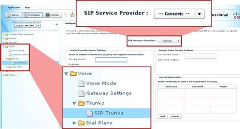
A summary of Cisco UBE features supported by CCP 2.3 include the features represented by the following CLI segments.
Global:
call threshold global total-calls low 7920 high 9000
ip domain name mydomain.com
ip name-server 10.25.135.23
Global VoIP Services:
voice service voip
allow-connections h323 to h323
allow-connections h323 to sip
allow-connections sip to h323
allow-connections sip to sip
address-hiding
supplementary-service h450.12
sip
outbound-proxy ipv4:5.5.5.5
early-offer forced
midcall-signaling passthru
header-passing error-passthru
g729 annexb-all
asserted-id pai
SIP UA:
sip-ua
sip-server ipv4:2.2.2.2
remote-party-id
registrar dns:cisoc.com
authentication username ciscocp password ciscocp
credentials username test password test realm test
Translation Rules:
voice translation-rule 2
rule 1 /12345/ /4083/
voice translation-profile test
translate called 2
translate calling 2
translate redirect-called 2
VoIP Dial Peer:
dial-peer voice 1 voip
description xxx
corlist incoming test
preference 5
session target sip-server
answer-address 408
destination-pattern 1234
session protocol sipv2
incoming called-number .T
voice-class codec 5
corlist outgoing test
dtmf-relay cisco-rtp
translation-profile outgoing test
translation-profile incoming test
codec g711alaw
Voice Class Codec:
voice class codec 5
codec preference 1 g711ulaw
codec preference 2 g729r8
Class of Restriction (COR):
dial-peer cor custom
name international
dial-peer cor list test
member international
4.2 SIP Trunk Security Recommendations
Like any other network and router device, Cisco UBE should be locked down against security attacks. Cisco UBE offers a variety of features to mitigate a range of attacks in the following categories:
● Denial of Service (DOS): Overrunning the system with traffic
● Identify and Service Theft: A rogue endpoint masquerading a legitimate endpoint and thereby using network services such as making toll calls
● Privacy: Unauthorized listening to, or recording of, calls

4.2.1 Service Provider (SP) SIP Trunk Security
When Cisco UBE is deployed in SP SIP trunk configurations, one of its major functions is to serve as a security point handing off enterprise traffic to the SP network. To ensure security for a SIP trunk deployment, the following features must be configured at a minimum:
● Access Lists (ACLs) to Allow/Deny Explicit Sources of Calls: Permit traffic only from the service provider SBC on the outside, and only the valid call agent(s) on the inside of the network. No other endpoint or source should be able to make or receive calls to Cisco UBE.
● CAC to Limit Call Arrival Rates and Max Active Calls: Deploy total call limits, per dial-peer call limits, call spike detection and CPU protection against potential SIP DOS attacks.
● Toll Fraud Lock-Down: Ensure that only legitimate endpoints can make authorized toll calls via Cisco UBE.
Additional optional features may be configured as needed:
● SIP Listen Port: Change the default 5060 SIP port to another port number.
voice service voip
sip
shutdown
voice service voip
sip
listen-port non-secure 2000 secure 2050
● SIP Registration: A SP SIP trunk requiring a registration sequence is more secure than one that doesn’t. However, many SPs do not currently support or offer SIP registration.
sip-ua
credentials username 1001 password 0822455D0A16 realm cisco.com
● SIP Digest Authentication: Cisco UBE responds to SIP Digest Authentication challenges from a SP call agent.
sip-ua
authentication username xxx password yyy
● SIP Hostname Validation: In addition to ACLs, this configuration can further limit the sources of traffic accepted by Cisco UBE.
sip-ua
permit hostname dns:example1.sip.com
permit hostname dns:example2.sip.com
permit hostname dns:10.10.10.10
● PPI/PAI: SP SIP trunks that offer P-Preferred-Identity (PPI) or P-Asserted-Identity (PAI) as per RFC3325 are more secure than those that do not. Configure these features if they are available from your SIP trunk SP. These features can be configured either at the global level or per dial-peer as given below. If the SIP trunk SP and your enterprise call agent both support these headers, then Cisco UBE can just pass them through. If your call agent does not support them, or you wish to translate one header type to another before handing them off to the SP, then use these features on Cisco UBE to do so.
voice service voip
sip
asserted-id pai
dial-peer voice 100 voip
voice-class sip asserted-id pai
voice service voip
sip
asserted-id ppi
dial-peer voice 100 voip
voice-class sip asserted-id ppi
● Firewall: The IOS Firewall may be collocated with Cisco UBE on the same router to provide IP protection for non-SIP traffic if an external firewall is not already deployed.
● Tcl: Tcl scripting applications can be configured on Cisco UBE dial-peers to do additional security checks before allowing or denying a call. Checks can be done against a short list of numbers held locally in router memory, or checks can be done against an external server or database. In this way, allowed list/blocked list applications can be built. Tcl scripts can also be written to query the caller for a PIN or authorization code before allowing the call.
● Encryption: Signaling (TLS) and media (Secure RTP, SRTP) encryption: SP SIP trunks providers do not offer TLS/SRTP encryption today, but may do so in future. Cisco UBE supports TLS to non-TLS connections and SRTP.
● Monitor CDR: Whether or not actual accounting information is required, it is recommended to monitor CDR from Cisco UBE to scan for call patterns and volumes that may indicate unauthorized use. Some toll fraud hackers bypass the enterprise call agent for the very purpose of not having their calls show up in the call agent CDR/billing records and instead address their fraudulent calls directly to the PRI gateway or SBC—therefore monitoring CDR from the gateway/SBC itself is important to see these call patterns. Also for call patterns where the hacker is on the PSTN and hairpins a call through your PRI gateway or SBC back out to the PSTN—these calls never hit your call agent and do not show up in call agent CDR.
Toll fraud is still the most prevalent security issue for devices that provide access to the PSTN, be they traditional PRI gateways or an SBC like Cisco UBE anchoring a PSTN SIP trunk. To protect against PSTN toll fraud, ensure the following features already discussed in the previous section are configured:
● ACLs
● SIP listen port change
● Tcl
● CDR
In addition to the above, it is recommended to configure:
● Explicit Incoming and Outgoing Dial-Peers: The more explicit you can make the “incoming called-number” (for an incoming dial-peer) or “destination-pattern” (outgoing dial-peer) the more secure it is. Avoid use of default incoming dial-peer 0 which is promiscuous and allows all incoming connections.
● Trunk Access Codes Using Translation Rules: Protect calls to expensive PSTN destinations or undesirable locations (perhaps international calls, calls to certain countries, etc.) with trunk access codes in front of the PSTN direct dial string. These codes can be transparent to your legitimate user base by inserting the code at your call agent (e.g. 89923 for calls to country-X) and deleting the code at Cisco UBE before passing the call to the PSTN. The use of this precludes a hacker directly addressing the SIP trunk and dialing direct to expensive locations (while bypassing your call agent).
● Close Unused H.323/SIP Ports and Transport Mechanisms: By default these ports are open when a voice-enabled software load is deployed on the router (either as a PRI gateway or Cisco UBE).
sip-ua
no transport tcp
no transport udp
4.2.3 New Security Operation in Cisco IOS 15.1.2T
To help mitigate toll fraud opportunities, as of 15.1.2T Cisco IOS no longer allows connections from “unknown” sources to connect by default. Only sources on the IP Trust List are allowed (by default) and all other calls are rejected.
IP addresses defined in the “session target ipv4:” commands on dial-peers are automatically included in the IP Trust List. Additional valid source IP addresses can be added manually to the Trust List if needed by using the following CLI:
voice service voip
ip address trusted list
ipv4 20.20.20.1
While it is recommended to use the increased security operation available in 15.1.2T, pre-15.1.2T IOS operation can be restored by using the CLI:
no ip address trusted authenticate
4.3 Monitoring Recommendations
The following aspects of Cisco UBE are recommended to be monitored.
● Router Inventory and Health
● Interface Health
● SIP Trunk Status
● Call Traffic
◦ Trunk utilization and H.323/SIP Session Capacity
◦ Call arrival rate
◦ Call success/failure statistics
◦ SIP retries statistics
◦ Transcoding Session Capacity and DSP Utilization
◦ Media Termination Point (MTP) Session Capacity
● Licensing and Call Admission Control
● Voice Quality
● Billing/CDR
The following table lists key “show” commands giving output that enables you to monitor Cisco UBE health, traffic and activity.
Table 22. Key “show” Commands on Cisco UBE
| Category |
Command |
Information Provided |
| Configuration |
show version |
Displays the version of the image on the router |
| show flash: |
Displays information about flash: file system |
|
| show ip interface brief |
Displays brief summary of IP status and configuration |
|
| show startup-config |
Displays the startup configuration on the router |
|
| show running-config |
Displays the present/running con configuration on the router |
|
| show debug |
Displays the debugs currently enabled |
|
| show voice iec desc <> |
Displays definition of an Internal Error Code |
|
| show logging |
Displays the contents of logging buffers |
|
| Traffic |
show call active voice |
Displays complete details of an active call like media settings, call statistics, SRTP on/off, etc. |
| show call active voice brief |
Displays a brief version of active voice calls, e.g. transmitted and received packets and duration of call |
|
| show call active voice compact |
Displays a compact version of active voice calls |
|
| show voip rtp connections |
Displays active RTP connections |
|
| show call history voice |
Displays calls stored in the history table for voice |
|
| Router Health |
show processes cpu sorted <1min/5min/5sec>” |
Displays sorted output based on percentage of CPU utilization |
| show processes cpu sorted history |
Displays CPU history information in a graph format |
|
| show memory processor |
Displays memory statistics |
|
| show process memory <> |
Displays memory per process |
|
| show memory debug leaks |
Runs the memory leak detector |
|
| show alignment |
Displays alignment data and spurious memory references |
|
| CAC |
show call threshold config |
Displays configured resource information |
| show call treatment config |
Displays call admission control information |
|
| show call treatment stats |
Displays call treatment statistics |
|
| SIP |
show sip-ua connections udp brief |
Displays summary of SIP UDP connection information |
| show sip-ua connections udp detail |
Displays details of SIP UDP connection information |
|
| show sip-ua connections tcp brief |
Displays summary of SIP TCP connection information |
|
| show sip-ua connections tcp detail |
Displays details of SIP TCP connection information |
|
| show sip-ua register status |
Displays SIP registration status |
|
| Transcoding and DSPs |
show diag |
Displays diagnostic and hardware information for port adapters and modules |
| show sdspfarm units |
Displays transcoder registration status |
|
| show sccp connection |
Displays the active SCCP connections |
|
| show sccp |
Displays SCCP protocol information |
|
| show dspfarm dsp active |
Displays the active DSPs |
|
| show call active voice | inc CoderTypeRate=” |
Displays call connectivity, codec and the media type information |
|
| show call active voice comp |
Displays codec information for transcoding calls |
|
| DTMF Relay |
show call active voice | inc tx_DtmfRelay |
Displays the DTMF-relay used for the call |
| Security |
show sip-ua connections tcp tls brief |
Displays summary information on whether the transport used for the call is TLS or not |
| Show sip-ua connections tcp tls detail |
Displays detailed information on whether the transport used for the call is TLS or not |
|
| Gatekeeper |
show gatekeeper status |
Displays if the Gatekeeper state is Up/Down |
| show gateway |
Displays status of H.323 gateway |
|
| show gatekeeper endpoints |
Displays E.164 endpoint register status |
|
| show gatekeeper calls |
Displays current gatekeeper call status |
|
| show gatekeeper zone prefix all |
Displays all zone and gateway registered E.164 prefixes |
|
| show gatekeeper gw-type-prefix |
Displays gateway Technology Prefix Table |
|
| show gatekeeper zone status |
Displays available bandwidth in ACF |
|
| show h323 gateway cause-codes |
Displays H.323 disconnect cause codes |
4.4 Troubleshooting Recommendations
The following procedure is recommended to collect usable debug information:
● Configure “logging buffer 10000000” and “no logging console”
● Enter the “clear logging” command
● Perform the test
● Collect the logs using following two commands
◦ term length 0
◦ show logging
The following table lists key “debug” commands giving output that enables you to troubleshoot problems on Cisco UBE.
Table 23. Key “debug” Commands on Cisco UBE
| Category |
Command |
| SIP and H.323 |
debug voip ccapi all |
| debug voip ccapi input |
|
| debug voip ccapi inout |
|
| debug voip dialpeer all |
|
| debug voip ipipgw |
|
| SIP |
debug ccsip all |
| H.323 |
debug cch323 all |
| debug h225 asn |
|
| debug h225 events |
|
| debug h245 asn |
|
| debug h245 events |
|
| Transcoding and MTP |
debug sccp all |
| debug sccp events |
|
| debug sccp messages |
|
| debug sccp errors |
|
| debug voip xcodemsp |
|
| Media |
debug rtpspi error |
| debug voip rtp error |
|
| debug voip app |
The following key “show” commands provide output that enables you to troubleshoot problems on Cisco UBE.
sh call history ?
fax Show calls stored in the history table for fax
media Show calls stored in the history table for media
video Show calls stored in the history table for video
voice Show calls stored in the history table for voice
!
sh voice call ?
<0-0> Voice interface slot #
status Show status for active calls
summary Summary of all voice calls
!
sh voip ?
debug Show voip debug info
rtp Display Real Time Protocol (RTP) information
!
sh voip rtp ?
connections Display all the active RTP connections
!
sh voice statistics ?
csr Show Call Statistics Records information
iec Show Internal Error Code information
interval-tag Show Voice Statistics time-range intervals
memory-usage Show current memory utilization of voice statistics
4.4.2 High-Traffic-Volume Troubleshooting (PCD)
Under high traffic conditions on an ISR G2 (e.g. a Cisco 3945 or 3945E) or an ASR (e.g. a Cisco ASR1006), the generic Cisco IOS debugging commands may be too verbose to allow effective debugging of a production Cisco UBE. Under these conditions the Per Call Debugging (PCD) tools can be used to minimize debug output to a particular call of interest.
PCD enables the configuration of debugging to be done to circular memory buffers rather than console output. Trigger conditions are set up to monitor the buffer contents and print out to the console only debug (from the memory buffers) that matches a particular trigger condition. Debug from the memory buffers can also be directed to an offline system for further analysis or interpretation.
Sample trigger points include:
● SIP 4xx, 5xx and 6xx error messages
● Q.850 cause codes
● CAC limits
◦ Call treatment – cause code busy
◦ Call treatment – cause code noQos
◦ Call treatment – cause code no-resource
A summary of configuring and using PCD include the following steps:
Step 1: Define buffers and buffer sizes
per-call num-buffer <num>
per-call buffer-size debug <num>
Step 2: Turn per-call debugging on/off
per-call shutdown
per-call active debug
per-call inactive
Step 3: Set trigger points
per-call trigger cause 1
per-call trigger cause 41
per-call trigger sip-message 404
per-call trigger sip-message 488
Step 4: Export debug buffer content
per-call export primary [flash | ftp | http | pram | rcp | tftp] secondary [flash | ftp | http | pram | rcp | tftp]
Step 5: Show buffer content status
show per-call stat
show per-call buffer list
show per-call buffer content <buf-id>
show voice per-call trigger
Step 6: Show buffer contents on console
router#show per-call buffer content ?
<0-10000000> Specify the buffer number
router#show per-call buffer content 1
Buffers are indexed/referenced based on the GUID of the call:
router#show per-call buffer list
No. GUID Usage Last Updated Status
=====================================================================
0 490C81D9-34E0-11DE 73402 Apr 30 17:08:00.784 PCD_BUFFER_INUSE
8656-E29654047181
1 00000000-0000-0000 0 PCD_BUFFER_FREE
0000-000000000000
2 00000000-0000-0000 0 PCD_BUFFER_FREE
0000-000000000000
3 00000000-0000-0000 0 PCD_BUFFER_FREE
0000-000000000000
4 00000000-0000-0000 0 PCD_BUFFER_FREE
0000-000000000000
The Cisco IOS IP Traffic Capture feature can be used to build protocol (SIP) ladder diagrams for protocol troubleshooting. This feature captures packets on an interface and builds a pcap file that can be copied to an offline system for protocol analysis by a tool such Wireshark (freeware, from www.wireshark.org).
A summary of capturing and analyzing SIP protocols information using these tools include the following steps:
Step 1: Configure a capture profile
! create profile
ip traffic-export profile TAC mode capture
bidirectional
incoming access-list 123
outgoing access-list 123
!
! access-list to filter only SIP messages (port 5060)
access-list 123 permit udp any any eq 5060
access-list 123 permit tcp any any eq 5060
!
! apply to an interface, default memory is 5M
interface fa0/0
ip traffic-export apply TAC [size <bytes>]
Step 2: Capture traffic with these exec (enable) level commands
router#traffic-export interface fa0/0 clear
router#traffic-export interface fa0/0 start
<capture the problem>
router#traffic-export interface fa0/0 stop
Note: The exec cmds don’t appear until a profile has been configured.
Step 3: Export the pcap file to a server
router#traffic-export interface fa0/0 copy ftp://x.x.x.x/capture.pcap
Step 4: Display a ladder diagram using Wireshark
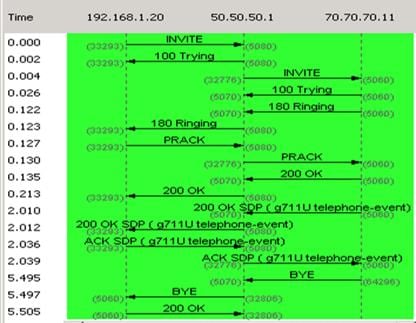
Note: Allows filtering of calling/called numbers when creating the flow graph.
The IP Traffic Capture tools are currently available on the ISR G1 and G2 series platforms only.
● AAA: Authentication, Authorization, and Accounting
● ACL: Access List
● ASR: Aggregation Services Routers
● CAC: Call Admission Control
● CDR: Call Detail Record
● CCE: Cisco Configuration Engine
● CCP: Cisco Configuration Professional
● CLI: Command Line Interface
● CLM: Cisco License Manager
● CUBE: Cisco Unified Border Element
● CUCM: Cisco Unified Communications Manager
● CUOM: Cisco Unified Operations Manager
● DOS: Denial of Service
● DSP: Digital Signal Processing
● DTMF: Dual-tone Multi Frequency
● EEM: Embedded Event Manager
● FQDN: Fully Qualified Domain Name
● GK: Gatekeeper
● GUI: Graphical User Interface
● GW: Gateway
● HA: High Availability
● HSRP: Hot Standby Router Protocol
● ICPIF: Calculated Planning Impairment Factor
● ISR: Integrated Services Router
● ISR G2: Integrated Services Router Generation 2
● LMS: LAN Management Solution
● MIB: Management Information Base
● MOS: Mean Opinion Score
● MTP: Media Termination Point
● NTP: Network Time Protocol
● OID: Object identifier
● OOD: Out of Dialog
● PBX: Private Branch Exchange
● PCD: Per Call Debugging
● PDD: Post Dial Delay
● PSTN: Public Switched Telephone Networks
● QoS: Quality of Service
● RADIUS: Remote Authentication Dial-in User Service
● RAI: Resource Availability Indicator
● RPID: Remote Party ID
● RSVP: Resource Reservation Protocol
● RTP: Real-time Protocol
● SBC: Session Border Controller
● SCCP: Skinny Client Control Protocol
● SIP: Session Initiation Protocol
● SLA: Service Level Agreement
● SNMP: Simple Network Management Protocol
● SP: Service Provider
● SRTP: Secure RTP
● Tcl: Tool Command Language
● TCP: Transmission Control Protocol
● TDM: Time Division Multiplexing
● TLS: Transport Layer Security
● UC: Unified Communications
● UDP: User Datagram Protocol
● UNI: User to Network Interface
● URI: Universal Resource Identifier
● VAD: Voice Activity Detection
To view buying options and speak with a Cisco sales representative, visit https://www.cisco.com/c/en/us/buy.html.
● Cisco UBE on Cisco.com
● Cisco Communications Transformations Whitepapers > Section on Whitepapers
● Cisco Interoperability Portal > Cisco Unified Border Element (CUBE)/SIP Trunking Solutions
● Cisco UBE IOS Configuration Documentation
● Cisco UBE IOS Configuration Application Notes and Examples Documentation
● Cisco IOS Voice Command Reference
● Cisco SRND Portal (CUCM and CVP SIP Trunk Documentation)
◦ CVP 7.0 SIP Trunk Integration
● Cisco.com MIB Locator tool
● Cisco.com SNMP Object Navigator tool
 Feedback