- Preface
- Product Overview
- Supported Features
- CT5760 Centralized Configuration Example
- Mobility Architecture
- Bring Your Own Device Security Configuration
- Secure WLAN Configuration
- 802.11ac Support on WLC5760 and Catalyst 3850
- Radio Resource Management Configuration
- CleanAir
- Configuring ClientLink (Beamforming)
- High Availability
- Interface Group
- Multicast Configuration
- Installing and Upgrading Software Image on a CT5760
- Adding WLC to Prime
- Application Visibility and Flexible Netflow
- Service Discovery Gateway (mDNS Gateway)
- QoS Configuration
Supported Features
The CT5760 WLC is an industry-leading platform designed for 802.11ac performance with maximum services, scalability, and high resiliency for mission-critical wireless networks. Through enhanced software programmable ASIC, it delivers a wide range of features highlighted in Table 2-1 .
For a complete list of features and specifications, refer to the Cisco 5760 Series Wireless Controller page and Data Sheet.
Cisco Controllers Comparisons
This table shows the Cisco high-scale controllers comparison at a glance:
New Operating System using Cisco IOS® Software CLI Commands
The CT5760 controllers use the same Cisco IOS® software CLI command used on the Cisco switches and routers. New wireless CLI commands have been added to the existing Cisco IOS® CLI. For a complete list of the wireless Cisco IOS® software CLI commands, refer to the Cisco 5700 Series Wireless LAN Controllers Command References document.
Licenses
Licenses are based on the Right-To-Use license model (per AP license price for the Catalyst 3850 and CT5760). AP licenses are enabled on the mobility controller. The mobility controller can be a Catalyst 3850 switch (or switches), CT5760, 5500, or WiSM2. There is not a separate license for mobility agent functionality (for example, CAPWAP termination on the switch). The same AP licenses can be used as before when the 5500/WiSM2 is used as mobility controller. AP licenses are transferable between Catalyst 3850 and CT5760, Catalyst 3850 and Catalyst 3850, and CT5760 and CT5760.
Please refer to the Cisco Right to Use Licensing FAQ for additional information.
Software Release Numbers
The CT5760 controller currently ships with release 3.2.01 or release 3.3.0. You can check this using the command:
Switch Ports Model SW Version SW Image Mode
------ ----- ----- ---------- ---------- ----
* 1 6 AIR-CT5760 03.03.01SE ct5760-ipservicesk9 INSTALL
It is recommended to upgrade to software release 3.3.3 and later. Latest software codes are available on Cisco.com. It is best practice to go through the release notes before upgrading to that software code. Please follow the steps in the Cisco IOS XE software upgrade document.
Supported Platforms

Note![]() AP1532 is an outdoor AP supported in Local Mode only. IOS controllers do not support MESH mode. Also, 2700 and 1532 APs are supported in Releases 3.6 and later.
AP1532 is an outdoor AP supported in Local Mode only. IOS controllers do not support MESH mode. Also, 2700 and 1532 APs are supported in Releases 3.6 and later.
Unified Access Deployment Modes
With the introduction of the CT5760 and Catalyst 3850, there are two deployment modes within the Cisco Unified Access Architecture - Centralized and Converged Access.
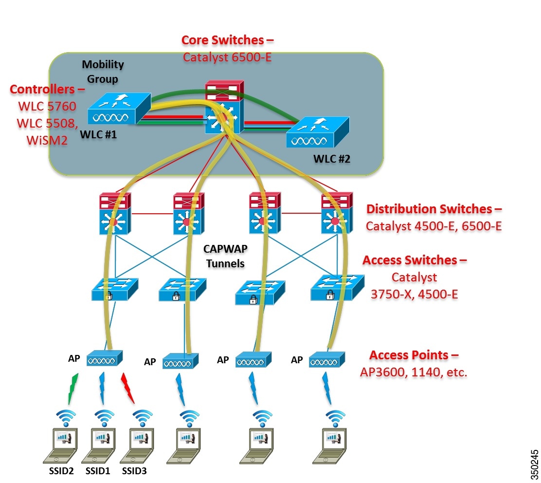
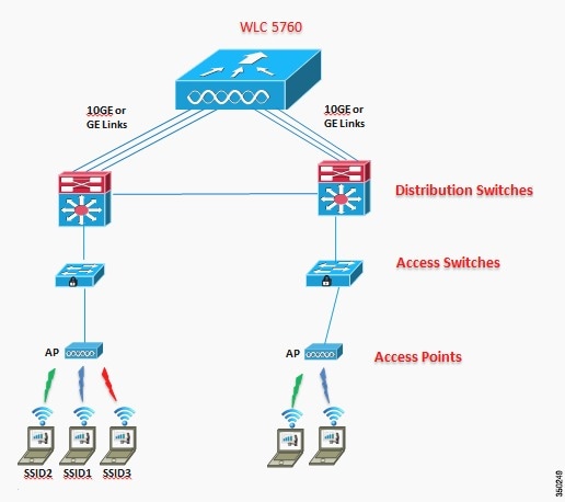
Centralized Mode
The centralized mode (also known as local mode on legacy controllers) is the same deployment model currently used today in the Cisco Unified Wireless Network (CUWN) solution set for wireless as well as wired connectivity. The current CUWN provides centralized tunneling of user traffic to the controller (data plane and control plane) and system-wide coordination for channel and power assignment, rogue detection, security attacks, interference, roaming, and so on.
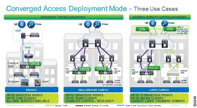
Converged Access Mode
Converged mode is an evolution of the current wireless deployments and offers an additional deployment mode for mobility. With the converged access model, there are a few design differences to note:
- The Catalyst 3850 can act as a mobility agent for terminating CAPWAP tunnels for locally connected APs.
- The Catalyst 3850 can act as a Mobility Controller (MC) for other mobility agent switches in small deployments.
- MC handles roaming across a switch peer group (SPG) (L2 / L3).
- Mobility agents within an SPG are fully meshed (auto-created at SPG formation).
Figure 2-2 Converged Access Deployment Mode
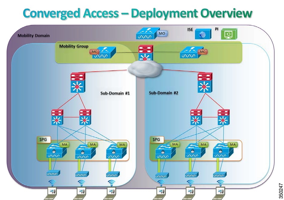
Converged Access Components
A few components are highlighted in order to understand the Converged Access model. These components are shown in Figure 2-3.
- Mobility Agent – Terminates CAPWAP tunnel from AP and handles the local client database.
- Mobility Controller – Manages mobility within and across sub-domains, RRM, CleanAir and roaming.
- Mobility Oracle – Superset of mobility controller, allows for scalable mobility management within a domain.
- Mobility Groups – The grouping of mobility controllers to enable fast and secure roaming.
- Switch Peer Group – Localizes traffic for roams within its distribution block.
Figure 2-3 Converged Access - Deployment Overview
This deployment guide focuses on the configuration of the new CT5760 feature set with the Cisco IOS® software. For detailed information on the new Catalyst 3850 wired/wireless switch and its deployment scenarios, refer to the Catalyst 3850 Deployment/Configuration Guides page.
Deployment Basics: Ports, Interfaces, WLAN
This section covers information about the CT5760 ports, interfaces, and WLANs.
Information about Ports
A port is a physical entity that is used for connections on the controller platform. Controllers have two types of ports: distribution system ports and a service port. The ports available on the CT5760 controller are shown in Figure 2-4
Figure 2-4 CT5760 Controller - Front and Rear View
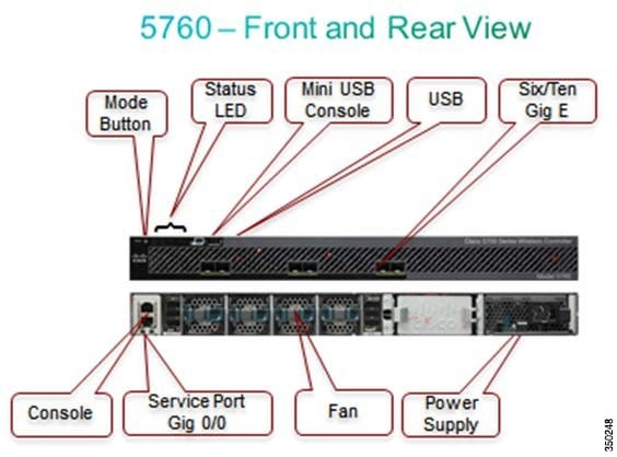
Management Port (Service Port) (RJ-45)
The Cisco 5760 Series Controllers have a 10/100/1000 copper Ethernet Management port (GE 0/0). The management port is reserved for out-of-band management of the controller, system recovery, and maintenance in the event of a network failure.
Console Ports (RJ-45) and Mini USB Type B port
The CT5760 WLC has two console ports: the RJ45 and Mini USB Type B port.
Note![]() You can use only one console port (either RJ-45 or mini USB). When you connect to one console port, the other is disabled.
You can use only one console port (either RJ-45 or mini USB). When you connect to one console port, the other is disabled.
USB Ports 0 (Type A):
The USB console port on the Cisco 5760 Series Controllers connects directly to the USB connector of a PC using a USB Type A-to-5-pin mini Type B cable.
SFP Distribution System Ports 1-6:
The Cisco 5760 Controllers have six 10 Gigabit Ethernet (GE) distribution system ports, through which the controller can manage multiple APs. Cisco 5760 controllers support a maximum of 1000 APs and have no restrictions on the number of APs per port. However, Cisco recommends using link aggregation (LAG) or EtherChannel to balance the load automatically. LAG is covered in another section in this document. The part numbers for the supported SFPs on the 10 GE ports are listed in Table 2-3 .
Information about Interfaces
An interface is a logical entity on the controller. The next-generation controllers contain multiple interfaces, but these interfaces should be configured:
1.![]() Wireless management interface (can be configured at setup time; mandatory)
Wireless management interface (can be configured at setup time; mandatory)
The wireless management interface is used for AP to controller discovery, mobility and Radio Resource Management (RRM). This interface is also used for in-band management: Telnet/SSH CLI, SNMP, and Web GUI.
2.![]() VLANs, which are considered dynamic interfaces, where WLAN traffic is mapped to them.
VLANs, which are considered dynamic interfaces, where WLAN traffic is mapped to them.
Information about WLANs
A WLAN associates a service set identifier (SSID) to a VLAN interface. It is configured with security, quality of service (QoS), radio policies, and other wireless network parameters. Up to 512 AP WLANs can be configured per controller.
WLANs are directly mapped to VLANs, which are mapped to physical interfaces.
Note![]() Cisco recommends that you assign one set of VLANs for WLANs and a different set of VLANs for management interfaces to ensure that controllers properly route VLAN traffic.
Cisco recommends that you assign one set of VLANs for WLANs and a different set of VLANs for management interfaces to ensure that controllers properly route VLAN traffic.
AP Join Controller Discovery Process
In a CAPWAP environment, a lightweight AP discovers a controller by using CAPWAP discovery mechanisms and then sends the controller a CAPWAP join request. The controller sends the AP a CAPWAP join response, allowing the AP to join the controller. When the AP joins the controller, the controller manages its configuration, firmware, control transactions, and data transactions.
APs must be discovered by a controller before they can become an active part of the network. The lightweight APs support the following controller discovery process:
- Layer 3 CAPWAP discovery: This feature can be enabled on different subnets from the AP and uses IP addresses and UDP packets rather the MAC addresses used by Layer 2 discovery.
- Locally stored controller IP address discovery: If the AP was previously associated to a controller, the IP addresses of the primary, secondary, and tertiary controllers are stored in the AP’s nonvolatile memory. This process of storing controller IP addresses on an AP for later deployment is known as priming the AP.
- DHCP server discovery: This feature uses DHCP option 43 to provide controller IP addresses to the APs. Cisco switches support a DHCP server option that is typically used for this capability. For more information about DHCP option 43, refer to the Configuring DHCP Option 43 for Lightweight Access Points document.
- DNS discovery: The AP can discover controllers through your DNS. In order for the AP to do so, you must configure your DNS to return controller IP addresses in response to CISCO- CAPWAP-CONTROLLER.localdomain, where localdomain is the AP domain name. When an AP receives an IP address and DNS information from a DHCP server, it contacts the DNS to resolve CISCO-CAPWAP-CONTROLLER.localdomain or CISCO-CAPWAP- CONTROLLER.localdomain. When the DNS sends a list of controller IP addresses, the AP sends discovery requests to the controllers.
Link Aggregation/Load Balancing/Port Redundancy
The Cisco 5760 WLC has no restrictions on the number of APs per port, but Cisco recommends using LAG or EtherChannel on each 10GE port to automatically balance the load.
LAG functionality is achieved for a CT5760 controller through configuration of EtherChannels in the Cisco IOS® software. Through EtherChannels, the controller dynamically manages port redundancy and load balances APs transparently to the user.
Information about Link Aggregation
Link Aggregation (LAG) or Etherchannel can be configured on the 5760 Controller. It bundles all of the controller's distribution system ports into a single port channel. The Cisco 5760 Controller supports Cisco Port Aggregation Protocol (PAgP) and industry-standard IEEE 802.3ad Link Aggregation Control Protocol (LACP). When LAG is enabled, the system dynamically manages port redundancy and load balances APs transparently to the user.
LAG simplifies controller configuration because you no longer need to configure primary and secondary ports for each interface. If any of the controller ports fail, traffic is automatically migrated to one of the other ports. As long as at least one controller port is functioning, the system continues to operate, APs remain connected to the network, and wireless clients continue to send and receive data.
Multiple LAGs
Multiple LAG groups can be configured to support configurations requiring connectivity to multiple switches for redundancy.
Configure the Controller and Neighbor Devices to Support LAG
Port-Channel configuration example on the 5760 controller:
WLC5760(config)#interface port-channel 1
WLC5760(config-if)#switchport trunk allowed vlan 70,80,90,100
WLC5760(config-if)#switchport mode trunk
WLC5760(config)#interface tenGigabitEthernet 1/0/1
WLC5760(config-if)#switchport trunk allowed vlan 70,80,90,100
WLC5760(config-if)#switchport mode trunk
WLC5760(config-if)#channel-group 1 mode active
WLC5760(config)#interface tenGigabitEthernet 1/0/6
WLC5760(config-if)#switchport trunk allowed vlan 70,80,90,100
WLC5760(config-if)#switchport mode trunk
WLC5760(config-if)#channel-group 1 mode active
Note![]() You might be required to enable ip dhcp snooping trust on the port-channel interface. Please refer to the DHCP Snooping and Trust Configuration on CT5760 for additional details.
You might be required to enable ip dhcp snooping trust on the port-channel interface. Please refer to the DHCP Snooping and Trust Configuration on CT5760 for additional details.
Port-Channel configuration should be done on the neighboring switch configuration to match the configuration on the controller.
- You can do LAG or Multi-LAG from the controller to more than one switch. For this, you must create port channels for both switches. This provides redundancy and scalability.
- AP manager interfaces is supported on the CT5760 WLAN controller similar to the AireOs controller. However, Cisco recommends using LAG for redundancy and load balancing instead of AP manager.
 Feedback