-
Cisco Aironet Access Point Software Configuration Guide for VxWorks
-
Preface
-
Overview
-
Using the Management Interfaces
-
Configuring the Radio and Basic Settings
-
Configuring VLANs
-
Configuring Filters and Quality of Service
-
Configuring Proxy Mobile IP
-
Configuring Other Settings
-
Security Setup
-
Network Management
-
Managing Firmware and Configurations
-
Management System Setup
-
Special Configurations
-
Diagnostics and Troubleshooting
-
Appendix A - Protocol Filter Lists
-
Appendix B - Channels, Power Levels, and Antenna Gains
-
Appendix C - Event Log Messages
-
Index
-
 Feedback
Table Of Contents
Settings on the Time Server Setup Page
Settings on the Boot Server Setup Page
Use Previous Configuration Server Settings
Read .ini File from File Server
DHCP Multiple-Offer Timeout (sec)
DHCP Requested Lease Duration (min)
DHCP Minimum Lease Duration (min)
Entering Web Server Settings and Setting Up Access Point Help
Settings on the Web Server Setup Page
Settings on the Name Server Setup Page
Settings on the FTP Setup Page
Association Table Display Setup
Association Table Filters Page
Settings on the Association Table Filters Page
Association Table Advanced Page
Settings on the Association Table Advanced Page
Handle Alerts as Severity Level
Maximum number of bytes stored per Alert packet
Maximum Number of Forwarding Table Entries
Rogue AP Alert Timeout (minutes)
RFC 1493 802.1D Statistics in MIB (dot1dTpFdbTable)
Aironet Extended Statistics in MIB (awcTpFdbTable)
Map Multicast Entries to Broadcast Entry
Block ALL Inter-Client Communications (PSPF)
Default Activity Timeout (seconds) Per Device Class
Settings on the Event Display Setup Page
How should time generally be displayed?
How should Event Elapsed (non-wall-clock) Time be displayed?
Severity Level at which to display events
Settings on the Event Handling Setup Page
Handle Alerts as Severity Level
Maximum number of bytes stored per Alert packet
Maximum memory reserved for Detailed Event Trace Buffer (bytes)
Download Detailed Event Trace Buffer
Event Notifications Setup Page
Settings on the Event Notifications Setup Page
Should Notify-Disposition Events generate SNMP Traps?
Should Notify-Disposition Events generate Syslog Messages?
Should Syslog Messages use the Cisco EMBLEM Format
IEEE SNMP Traps Should Generate the Following Notifications
Configuring Other Settings
This chapter identifies and provides information on how to configure other settings on the access point, such as servers and association tables.
This chapter contains the following sections:
•
Association Table Display Setup
Server Setup
This section describes how to configure the server to support access point features. You use separate management system pages to enter server settings. The server setup pages are described in the following sections:
•
•
•
•
Note
Entering Time Server Settings
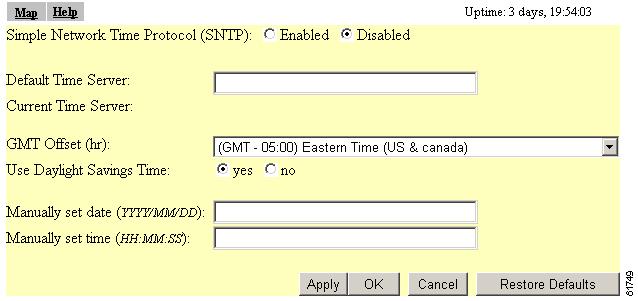
You use the Time Server Setup page to enter time server settings. Figure 7-1 shows the Time Server Setup page:
Figure 7-1 Time Server Setup Page
Follow this link path to reach the Time Server Setup page:
1.
2.
Settings on the Time Server Setup Page
The Time Server Setup page contains the following settings:
The page also displays the IP address of the time server, if one is assigned.
Simple Network Time Protocol
Select Enabled or Disabled to turn Simple Network Time Protocol (SNTP) on or off. If your network uses SNTP, select Enabled.
Default Time Server
If your network has a default time server, enter the server's IP address in the Default Time Server entry field.
The Current Time Server line under the entry field reports the time server the access point is currently using.
Note
GMT Offset (hr)
The GMT Offset drop-down menu lists the world's time zones relative to Greenwich Mean Time (GMT). Select the time zone in which the access point operates.
Use Daylight Savings Time
Select yes to have the access point automatically adjust to Daylight Savings Time.
Manually Set Date and Time
Enter the current date and time in the entry fields to override the time server or to set the date and time if no server is available.
When entering the date and time, use forward-slashes to separate the year, month, and day, and use colons to separate the hours, minutes, and seconds. For example, you would enter 2001/02/17 for February 17, 2001, and 18:25:00 for 6:25 pm.
Entering Boot Server Settings
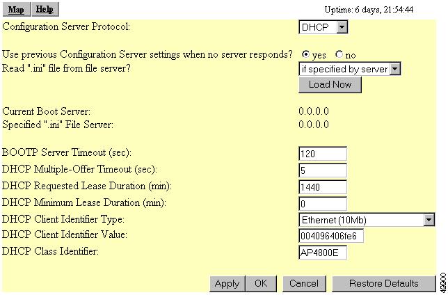
You use the Boot Server Setup page to configure the access point for your network's BOOTP or DHCP servers for automatic assignment of IP addresses. Figure 7-2 shows the Boot Server Setup page:
Figure 7-2 Boot Server Setup Page
Follow this link path to reach the Boot Server Setup page:
1.
2.
Settings on the Boot Server Setup Page
The Boot Server Setup page contains the following settings:
•
•
•
•
•
•
The page also shows the IP address of the current boot server and specified ".ini" file server.
Configuration Server Protocol
Use the Configuration Server Protocol drop-down menu to select your network's method of IP address assignment. The menu contains the following options:
•
•
•
Use Previous Configuration Server Settings
Select yes to have the access point save the boot server's most recent response. The access point uses the most recent settings if the boot server is unavailable.
Read .ini File from File Server
Use this setting to have the access point use configuration settings in an .ini file on the BOOTP or DHCP server or the default file server. Files with .ini extensions usually contain configuration information used during system start-up. The drop-down menu contains the following options:
•
•
•
The Load Now button under the drop-down menu tells the access point to read an .ini file immediately.
The Current Boot Server line under the drop-down menu lists the server that responded to the access point's boot request. If all zeros appear, it means that the access point is not using BOOTP/DHCP or that no server responded to the BOOTP/DHCP request. The Specified ".ini" File Server line lists the IP address of the server where the .ini file is stored. If all zeroes appear, it means that no file server is set up to provide an .ini file.
BOOTP Server Timeout (sec)
This setting specifies the length of time the access point waits to receive a response from a single BOOTP server. Enter the number of seconds the access point should wait. This setting applies only when you select BOOTP from the Configuration Server Protocol drop-down menu.
DHCP Multiple-Offer Timeout (sec)
This setting specifies the length of time the access point waits to receive a response when there are multiple DHCP servers. Enter the number of seconds the access point should wait.
DHCP Requested Lease Duration (min)
This setting specifies the length of time the access point requests for an IP address lease from your DHCP server. Enter the number of minutes the access point should request.
DHCP Minimum Lease Duration (min)
This setting specifies the shortest amount of time the access point accepts for an IP address lease. The access point ignores leases shorter than this period. Enter the minimum number of minutes the access point should accept for a lease period.
DHCP Client Identifier Type
Use this optional setting to include a class identifier type in the DHCP request packets the access point sends to your DHCP server. Your DHCP server can be set up to send responses according to class identifier type. If most of the client devices using the access point are the same device type, you can select that device type to be included in the DHCP request packet.
Use Ethernet (10Mb), the default setting, if you do not intend to set up your DHCP server to send responses according to class identifier type.
If you want to include a unique value in the DHCP Client Identifier Value field (the setting under DHCP Client Identifier Type on the Boot Server Setup page), select Other - Non Hardware.
Table 7-1 lists the options in the DHCP Client Identifier Type drop-down menu.
DHCP Client Identifier Value
Use this setting to include a unique identifier in the access point's DHCP request packet. This field contains the access point's MAC address by default. If you select Other - Non Hardware from the DHCP Client Identifier Type drop-down menu, you can enter up to 255 alphanumeric characters. If you select any other option from the DHCP Client Identifier Type drop-down menu, you can enter up to 12 hexadecimal characters. Hexadecimal characters include the numbers 0 through 9 and the letters A through F.
DHCP Class Identifier
Your DHCP server can be set up to send responses according to the group to which a device belongs. Use this field to enter the access point's group name. The DHCP server uses the group name to determine the response to send to the access point. The access point's DHCP class identifier is a vendor class identifier.
Entering Web Server Settings and Setting Up Access Point Help
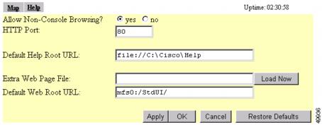
You use the Web Server Setup page to enable browsing to the web-based management system, specify the location of the access point Help files, and enter settings for a custom-tailored web system for access point management. Figure 7-3 shows the Web Server Setup page:
Figure 7-3 Web Server Setup Page
Follow this link path to reach the Web Server Setup page:
1.
2.
Settings on the Web Server Setup Page
The Web Server Setup page contains the following settings:
Allow Non-Console Browsing
Select yes to allow browsing to the management system. If you select no, the management system is accessible only through the console and Telnet interfaces.
HTTP Port
This setting determines the port through which your access point provides web access. Your System Administrator should be able to recommend a port setting.
Default Help Root URL
This entry tells the access point where to look for the Help files. The Help button on each management system page opens a new browser window displaying help for that page. You can point to the help files in one of the following locations:
•
•
[system name]\[directory]\wireless\help
•
file:///[drive letter]:\[folder or subdirectory]\wireless\help
Extra Web Page File
If you need to create an alternative to the access point's management system, you can create HTML pages and load them into the access point. You use this entry field to specify the filename for your HTML page stored on the file server.
Click Load Now to load the HTML page.
Default Web Root URL
This setting points to the access point management system's HTML pages. If you create alternative HTML pages, you should change this setting to point to the alternative pages. The default setting is:
mfs0:/StdUI/
Entering Name Server Settings
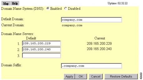
You use the Name Server Setup page to configure the access point to work with your network's Domain Name System (DNS) server. Figure 7-4 shows the Name Server Setup page:
Figure 7-4 The Name Server Setup Page
Follow this link path to reach the Name Server Setup page:
•
•
Settings on the Name Server Setup Page
The Name Server Setup page contains the following settings:
The page also displays the current domain, if one is in use.
Domain Name System
If your network uses a Domain Name System (DNS), select Enabled to direct the access point to use the system. If your network does not use DNS, select Disabled.
Default Domain
Enter the name of your network's IP domain in the entry field. Your entry might look like this:
mycompany.com
The Current Domain line under the entry field lists the domain that is serving the access point. The current domain might be different from the domain in the entry field if, on the Boot Server Setup page, you have DHCP or BOOTP set as the Configuration Server Protocol, but you selected No for the setting "Use previous Configuration Server settings when no server responds?"
Domain Name Servers
Enter the IP addresses of up to three domain name servers on your network. The Current lines to the right of the entry fields list the servers the access point is currently using, which may be specified by the DHCP or BOOTP server.
Domain Suffix
In this entry field, enter the portion of the full domain name that you would like omitted from access point displays. For example, in the domain "mycompany.com" the full name of a computer might be "mycomputer.mycompany.com." With domain suffix set to "mycompany.com," the computer's name would be displayed on management system pages as simply "mycomputer."
Entering FTP Settings
You use the FTP Setup page to assign File Transfer Protocol settings for the access point. All non-browser file transfers are governed by the settings on this page. Figure 7-5 shows the FTP Setup page:
Figure 7-5 The FTP Setup Page
Follow this link path to reach the FTP Setup page:
•
•
Settings on the FTP Setup Page
The FTP Setup page contains the following settings:
File Transfer Protocol
Use the drop-down menu to select FTP or TFTP (Trivial File Transfer Protocol). TFTP is a relatively slow, low-security protocol that requires no username or password.
Default File Server
Enter the IP address or DNS name of the file server where the access point should look for FTP files.
FTP Directory
Enter the file server directory that contains the firmware image files.
FTP User Name
Enter the username assigned to your FTP server. You don't need to enter a name in this field if you select TFTP as the file transfer protocol.
FTP User Password
Enter the password associated with the file server's username. You don't need to enter a password in this field if you select TFTP as the file transfer protocol.
Routing Setup
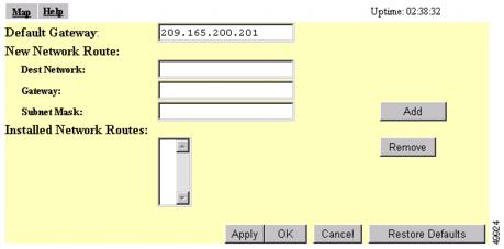
You use the Routing Setup page to configure the access point to communicate with the IP network routing system. You use the page settings to specify the default gateway and to build a list of installed network route settings. Figure 7-6 shows the Routing Setup page.
Figure 7-6 Routing Setup Page
Follow this link path to reach the Routing Setup page:
1.
2.
Entering Routing Settings
The Routing Setup page contains the following settings:
•
Default Gateway
Enter the IP address of your network's default gateway in this entry field. The entry 255.255.255.255 indicates no gateway.
New Network Route Settings
You can define additional network routes for the access point. To add a route to the installed list, fill in the three entry fields and click Add. To remove a route from the list, highlight the route and click Remove. The three entry fields include:
•
•
•
Installed Network Routes List
The list of installed routes provides the destination network IP address, the gateway, and the subnet mask for each installed route.
Association Table Display Setup
You use the Association Table Filters and the Association Table Advanced pages to customize the display of information in the access point's Association Table.
Association Table Filters Page
Figure 7-7 shows the Association Table Filters page.
Figure 7-7 Association Table Filters Page
Follow this link path to reach the Association Table Filters page:
1.
2.
You can also reach the Association Table Filters page through the "additional display filters" link on the Association Table page. When you reach the page through the "additional display filters" link, four buttons appear at the bottom of the page that are different from the standard buttons on management system pages. The buttons include:
•
•
•
•
Settings on the Association Table Filters Page
The Association Table Filters page contains the following settings:
Stations to Show
Select the station types that you want to be displayed in the Association Table. If you select all station types, all stations of these types appear in the access point's Association Table.
Fields to Show
The fields you select here are the column headings for the Association Table. Fields include:
•
•
–
–
–
•
•
•
•
•
•
•
–
–
–
–
–
Packets To/From Station
Use these settings to display packet volume information in the Association Table. Select Total to display the total number of packets to and from each station on the network.
Select Alert to display the number of alert packets to and from each station on the network for which you have activated alert monitoring. Select the Alert checkbox on a device's Station page to activate alert monitoring for that device. See the "Using Station Pages" section for details on Station pages.
The Total and Alert selections both add a column to the Association Table.
Bytes To/From Station
Use these settings to display byte volume information in the Association Table. Select Total to display the total number of bytes to and from each station on your wireless network. Select Alert to display the number of alert bytes to and from each station on the wireless network. Both selections add a column to the Association Table.
Primary Sort
This setting determines the information that appears in the first column in the Association Table. Choices available are:
•
•
•
•
•
•
•
Secondary Sort
This setting determines the information that appears in the second column in the Association Table. All primary sort options, except Parent, are available for the secondary sort.
Association Table Advanced Page
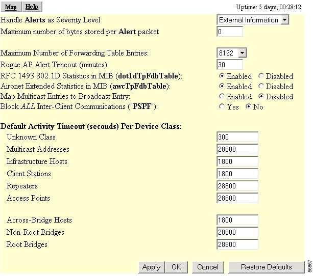
You use the Association Table Advanced page to control the total number of devices the access point can list in the Association Table and the amount of time the access point continues to track each device class when a device is inactive. Figure 7-8 shows the Association Table Advanced page.
Figure 7-8 Association Table Advanced Page
Follow this link path to reach the Association Table Advanced page:
1.
2.
Settings on the Association Table Advanced Page
The Association Table Advanced page contains the following settings:
•
•
•
•
•
•
•
•
•
Handle Alerts as Severity Level
This setting determines the Severity Level at which Station Alerts are reported in the Event Log. This setting also appears on the Event Handling Setup page. You can choose from four Severity Levels:
•
•
•
•
Maximum number of bytes stored per Alert packet
This setting determines the maximum number of bytes the access point stores for each Station Alert packet when packet tracing is enabled. If you use 0 (the default setting), the access point does not store bytes for Station Alert packets; it only logs the event. See the "Event Handling Setup Page" section for instructions on enabling packet tracing.
Maximum Number of Forwarding Table Entries
This setting determines the maximum number of devices that can appear in the Association Table.
Rogue AP Alert Timeout (minutes)
When an access point detects a rogue access point, it sends an alert message to the system log. This setting specifies the amount of time in minutes the access point transmits the alert message. When the timeout is reached, the access point stops sending the alert message.
RFC 1493 802.1D Statistics in MIB (dot1dTpFdbTable)
Use this setting to enable or disable the storage of detailed RFC 1493 802.1D statistics in access point memory. When you disable extended statistics you conserve memory, and the access point can include more devices in the Association Table.
Aironet Extended Statistics in MIB (awcTpFdbTable)
Use this setting to enable or disable the storage of detailed Aironet extended statistics in access point memory. When you disable extended statistics you conserve memory, and the access point can include more devices in the Association Table.
Map Multicast Entries to Broadcast Entry
Use this setting to make the access point or bridge more virus resistant. Some viruses send entire 1000+ blocks of multicast MAC addresses to the network, which overwhelms the access point's forwarding table. Setting this parameter to enabled maps all multicast MAC addresses into the broadcast address (without changing the packet's MAC address). When this parameter is enabled, the access point is not able to distinguish between multicast and broadcast addresses.
Block ALL Inter-Client Communications (PSPF)
Publicly Secure Packet Forwarding (PSPF) prevents client devices associated to an access point from inadvertently sharing files with other client devices on the wireless network. It provides Internet access to client devices without providing other capabilities of a LAN. With PSPF enabled, client devices cannot communicate with other client devices on the wireless network. This feature is useful for public wireless networks like those installed in airports or on college campuses.
Note
Default Activity Timeout (seconds) Per Device Class
These settings determine the number of seconds the access point continues to track an inactive device depending on its class. A setting of zero tells the access point to track a device indefinitely no matter how long it is inactive. A setting of 300 equals 5 minutes; 1800 equals 30 minutes; 28800 equals 8 hours.
Event Notification Setup
You use the Event Display Setup, Event Handling Setup, and Event Notifications Setup pages to customize the display of access point events (alerts, warnings, and normal activity).
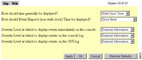
Event Display Setup Page
You use the Event Display Setup page to determine how time should be displayed on the Event Log. In addition, you can determine what severity level is significant enough to display an event. Figure 7-9 shows the Event Display Setup page.
Figure 7-9 The Event Display Setup Page
Follow this link path to reach the Event Display Setup page:
1.
2.
Settings on the Event Display Setup Page
The Event Display Setup page contains the following settings:
•
•
•
How should time generally be displayed?
You use this drop-down menu to determine whether the events in the Event Log are displayed as system uptime or wall-clock time. If you select system uptime, the events are displayed either since the boot or since the last time the Event Log was displayed. If you select wall-clock time, the events are displayed in a YY:MM:DD HH:MM:SS format. If time has not been set on the access point (either manually or by a time server), the time display appears as uptime regardless of this selection.
How should Event Elapsed (non-wall-clock) Time be displayed?
Choose to display event time since the last boot-up of the access point or the time that has elapsed since the event occurred.
Severity Level at which to display events
When an event occurs, it may be displayed immediately on the console, on the console log, or on the GUI log for read purposes only. The event may also be recorded. (You control display and recording of events through the Event Handling Setup page; see the "Event Handling Setup Page" section for details.) Use the drop-down menus to choose one of the sixteen severity levels for each display area. Table 7-2 lists the severity levels
These selections affect display of events only. They are used to filter information, not to remove it from the Event Log. To remove information from the Event Log, click Purge Log on the Event Log page.
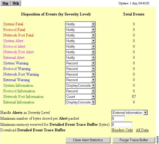
Event Handling Setup Page
You use the Event Handling Setup page to determine how notification of the fatal, alert, warning, and information events should occur. You can choose to only count the events, display them to the console but not store them, record them after displaying them on the console, or notify someone of the occurrence after displaying and recording the event. Figure 7-10 shows the Event Handling Setup page.
Figure 7-10 The Event Handling Setup Page
Follow this link path to reach the Event Handling Setup page:
1.
2.
Settings on the Event Handling Setup Page
The Event Handling Setup page contains the following settings:
•
•
•
•
Disposition of Events
The event settings control how events are handled by the access point: counted, displayed in the log, recorded, or announced in a notification. The settings are color coded: red for fatal errors, magenta for alerts, blue for warnings, and green for information. You select an option from each setting's drop-down menu. Each option includes and builds upon the previous option.
•
•
•
•
Handle Alerts as Severity Level
You use this setting to set a severity level for Station Alerts. Use the drop-down menu to choose one of the sixteen severity levels. Table 7-2 lists the severity levels in the menu. The *silent* option is not available for station events, however.
Maximum number of bytes stored per Alert packet
Enter the number of bytes the access point should store for each packet. If you want to see the entire contents of each packet, enter 1600; if you want to see only the packet header, enter 64.
Maximum memory reserved for Detailed Event Trace Buffer (bytes)
Enter the number of bytes reserved for the Detailed Event Trace Buffer. The Detailed Event Trace Buffer is a tool for tracing the contents of packets between specified stations on your network.
After you reserve space for the trace buffer, browse to a device's Station page and select the Alert checkboxes in the To Station and From Station columns. See the "Browsing to Network Devices" section for instructions on opening a device's Station page.
Download Detailed Event Trace Buffer
Use these links to view Headers Only or All Data in the detailed trace buffer. The number of bytes saved per packet is controlled on the Association Table Advanced Setup page.
If your browser is Netscape Communicator, click the links with your left mouse button to view the trace data. Click the links with your right mouse button and select Save Link As to save the data in a file.
Clear Alert Statistics
Click this button to reset the alert tallies to 0. The Clear Alert Statistics button clears the by-MAC-address alert statistics. You can see them when you add the alert columns to the association table summary status.
Purge Trace Buffer
Click this button to delete the packet traces from the Event Trace Buffer.
Event Notifications Setup Page
You use the Event Notifications Setup page to enable and configure notification of fatal, alert, warning, and information events to destinations external to the access point, such as an SNMP server or a Syslog system.
Note
Figure 7-11 shows the Event Notifications Setup page.
Figure 7-11 Event Notifications Setup Page
Follow this link path to reach the Event Notifications Setup page:
1.
2.
Settings on the Event Notifications Setup Page
The Event Notifications Setup page contains the following settings:
•
•
•
•
The page also displays the IP address of the network default syslog destination.
Should Notify-Disposition Events generate SNMP Traps?
Select yes to send event notifications to an SNMP server.
Note
SNMP Trap Destination
Type the IP address or the host name of the server running the SNMP Management software. This setting also appears on the SNMP Setup page.
SNMP Trap Community
Type the SNMP community name. This setting also appears on the SNMP Setup page.
Should Notify-Disposition Events generate Syslog Messages?
Select yes to send event notifications to a Syslog server.
Should Syslog Messages use the Cisco EMBLEM Format
When this setting is enabled, the access point generates EMBLEM (Baseline Manageability Specification) standard compliant system log messages:
ipaddress Counter: [yyyy mmm dd hh:mm:ss TimeZone +/- hh:mm]: %FACILTY- SEVERITY-MNEMONIC:
Message-text
Example without timestamp:
192.168.12.83: %APBR-6-STA_ASSOC_OK: [AP350-12] Station [TEST-LPT]000750abcd2a AssociatedExample with timestamp:
192.168.85:2002 SEP 12 13:52:12 PST -08:00: %APBR-6-STA_ASSOC_OK: [AP350-12] Station
[TEST-LPT]000750abcd2a Associated
The timestamp is optional and included in the message only when the wall clock time is set on the access point. The facility code for all messages is APBR.
Syslog Destination Address
Type the IP address or the host name of the server running Syslog.
The Network Default Syslog Destination line under the syslog destination address field lists the syslog destination address provided by the DHCP or BOOTP server. This default syslog destination is only used if the syslog destination address field is blank.
Syslog Facility Number
Type the Syslog Facility number for the notifications. The default setting is 16, which corresponds to the Local0 facility code.
IEEE SNMP Traps Should Generate the Following Notifications
You can designate how the SNMP traps handles the following client events:
•
•
•
You can set the following options for each event:
•
•
•
•