-
Cisco Aironet Access Point Software Configuration Guide for VxWorks
-
Preface
-
Overview
-
Using the Management Interfaces
-
Configuring the Radio and Basic Settings
-
Configuring VLANs
-
Configuring Filters and Quality of Service
-
Configuring Proxy Mobile IP
-
Configuring Other Settings
-
Security Setup
-
Network Management
-
Managing Firmware and Configurations
-
Management System Setup
-
Special Configurations
-
Diagnostics and Troubleshooting
-
Appendix A - Protocol Filter Lists
-
Appendix B - Channels, Power Levels, and Antenna Gains
-
Appendix C - Event Log Messages
-
Index
-
 Feedback
Table Of Contents
Incorporating Wireless Devices into VLANs
Network Configuration Examples
Repeater Unit that Extends Wireless Range
Central Unit in an All-Wireless Network
Overview
Cisco Aironet access points are wireless LAN transceivers that serve as the center point of a stand-alone wireless network or as the connection point between wireless and wired networks. In large installations, wireless users within radio range of an access point can roam throughout a facility while maintaining seamless, uninterrupted access to the network.
The access point uses a browser-based management system, but you can also configure the access point using a terminal emulator, a Telnet session, Secure Shell (SSH), or Simple Network Management Protocol (SNMP).
This chapter provides information on the following topics:
•
Network Configuration Examples
Key Features
This section describes the key features of the access point firmware. The following are the key features of this firmware version:
•
•
•
•
•
–
–
–
–
•
–
–
•
•
–
–
–
–
•
Management Options
You can use the access point management system through the following interfaces:
•
•
•
The access point's management system pages are organized the same way for the web- browser interface and the CLI. The examples in this manual are all taken from the browser interface. "Using the Management Interfaces," provides a detailed description of each management option.
Roaming Client Devices
If you have more than one access point in your wireless LAN, wireless client devices can roam seamlessly from one access point to another. The roaming functionality is based on signal quality, not proximity. When a client's signal quality drops, it roams to another access point.
Wireless LAN users are sometimes concerned when a client device stays associated to a distant access point instead of roaming to a closer access point. However, if a client's signal to a distant access point remains strong, the client will not roam to a closer access point. If client devices checked constantly for closer access points, the extra radio traffic would slow throughput on the wireless LAN.
Quality of Service Support
The access point now supports Cisco's QoS, primarily in the area of wireless VoIP telephones from Spectralink and Symbol Technologies Corporation. The access point also provides priority classification, prioritized queueing, and prioritized channel access for other downlink IEEE 802.11 traffic such as streaming audio or video traffic.
With this software release, the access point does not include any QoS enhancements in Cisco IEEE 802.11 client software.
What is QoS?
QoS refers to the ability of a network to provide improved service to selected network traffic over various underlying technologies including Ethernet and wireless LANs. In particular, QoS features provide improved and more predictable network service by providing the following services:
•
•
•
•
•
Limitations and Restrictions
The QoS implementation on the access point has the following limitations and restrictions:
•
•
•
•
•
•
Related Documents
The following documents provide more detailed information pertaining to QoS design and configuration:
•
•
These documents are available on Cisco.com.
VLAN Support
Version 12.01T supports VLAN technology by mapping SSIDs to VLANs. With the multiple-SSID capability, the access point can support up to 16 VLAN subnets.
What is a VLAN?
A switched network can be logically segmented into virtual local area networks (VLANs), on a physical or geographical basis, or by functions, project teams, or applications. For example, all workstations and servers used by a particular workgroup team can be connected to the same VLAN regardless of their physical connections to the network or the fact that they might be intermingled with devices for other teams. Reconfiguration of VLANs can be done through software rather than physically unplugging and moving devices or wires.
A VLAN can be thought of as a broadcast domain that exists within a defined set of switches. A VLAN consists of a number of end systems, either hosts or network equipment (such as bridges and routers), connected by a single bridging domain. The bridging domain is supported on various pieces of network equipment, such as LAN switches that operate bridging protocols between them with a separate group for each VLAN.
VLANs are created to provide the segmentation services traditionally provided by routers in LAN configurations. Routers in VLAN topologies provide broadcast filtering, security, address summarization, and traffic-flow management. None of the switches within the defined group will bridge any frames, not even broadcast frames, between two VLANs. Several key issues must be considered when designing and building switched LAN networks.
•
•
•
•
•
•
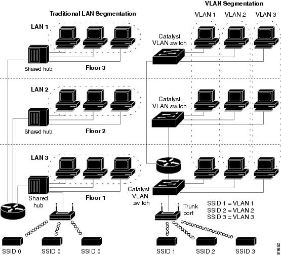
VLANs are extended into the wireless realm by adding IEEE 802.1Q tag awareness to the access point. Frames destined for wireless LAN clients on different VLANs are transmitted by the access point wirelessly on different SSIDs with different WEP keys. The only clients that can receive and process packets are those with the correct WEP keys. Conversely, packets coming from a client associated with a certain VLAN are 802.1Q tagged before they are forwarded onto the wired network.
Figure 1-1 illustrates the difference between traditional physical LAN segmentation and logical VLAN segmentation with wireless devices connected.
Figure 1-1 LAN Segmentation and VLAN Segmentation with Wireless Components
Related Documents
The following documents provide more detailed information pertaining to VLAN design and configuration:
•
•
•
•
Incorporating Wireless Devices into VLANs
A WLAN is generally deployed in an enterprise campus or branch office for increased efficiency and flexibility. WLANs are one of the most effective methods for connecting to an enterprise network. With version 12.01T, you can configure your wireless devices to operate in a VLAN.
The basic wireless components of a VLAN consist of an access point and a set of clients associated to it using wireless technology. The access point is physically connected through a trunk port to the network switch on which the VLAN is configured. The physical connection to the VLAN switch is through the access point's Ethernet port.
In fundamental terms, the key to configuring an access point to connect to a specific VLAN is by configuring an SSID to map to that VLAN. Because VLANs are identified by a VLAN ID, it follows that if an SSID on an access point is configured to map to a specific VLAN ID, a connection to the VLAN is established. When this connection is made, associated wireless client devices having the same SSID are able to access the VLAN through the access point. The VLAN processes data to and from the clients the same way that it processes data to and from wired connections. The fact that the client is wireless has no impact on the VLAN.
The VLAN feature now enables users to deploy wireless devices with greater efficiency and flexibility. For example, one access point can now handle the specific requirements of multiple users having widely varied network access and permissions. Without VLAN capability, multiple access points, one for each VLAN, would have to be employed to serve classes of users based on the access and permissions they were assigned.
A VLAN Example
The following simplified example shows how wireless devices can be used effectively in a VLAN environment on a college campus. In this example, three levels of access are available through VLANs configured on the physical network:
•
•
•
In this scenario, a minimum of three VLAN connections would be required: one for each level of access discussed above. The access point can handle up to 16 SSIDs; therefore, the following basic design could be employed as shown in Table 1-1.
Table 1-1 Access Level SSID and VLAN Assignment
Student
Student
01
Faculty
Faculty
02
Management
Management
03
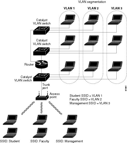
Using this design, setting up the clients is based on the level of access each user requires. A typical network diagram using this design would look like the one shown in Figure 1-2.
Figure 1-2 VLAN Example
Network Configuration Examples
This section describes the access point's role in three common wireless network configurations. The access point's default configuration is as a root unit connected to a wired LAN or as the central unit in an all-wireless network. The repeater role requires a specific configuration.
Root Unit on a Wired LAN
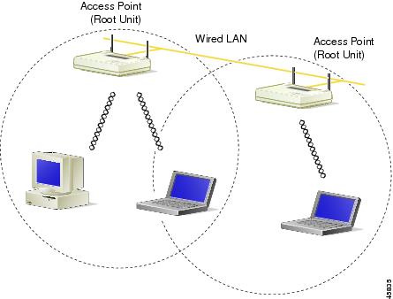
An access point connected directly to a wired LAN provides a connection point for wireless users. If more than one access point is connected to the LAN, users can roam from one area of a facility to another without losing their connection to the network. As users move out of range of one access point, they automatically connect to the network (associate) through another access point. The roaming process is seamless and transparent to the user. Figure 1-3 shows access points acting as root units on a wired LAN.
Figure 1-3 Access Points as Root Units on a Wired LAN
Repeater Unit that Extends Wireless Range
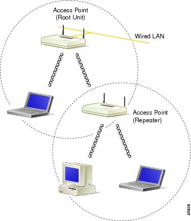
An access point can be configured as a stand-alone repeater to extend the range of your infrastructure or to overcome an obstacle that blocks radio communication. The repeater forwards traffic between wireless users and the wired LAN by sending packets to either another repeater or to an access point connected to the wired LAN. The data is sent through the route that provides the best performance for the client. Figure 1-4 shows an access point acting as a repeater. Consult the "Setting Up a Repeater Access Point" section for instructions on setting up an access point as a repeater.
Figure 1-4 Access Point as Repeater
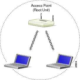
Central Unit in an All-Wireless Network
In an all-wireless network, an access point acts as a stand-alone root unit. The access point is not attached to a wired LAN; it functions as a hub linking all stations together. The access point serves as the focal point for communications, increasing the communication range of wireless users. Figure 1-5 shows an access point in an all-wireless network.
Figure 1-5 Access Point as Central Unit in All-Wireless Network