-
Cisco Aironet Access Point Software Configuration Guide for VxWorks
-
Preface
-
Overview
-
Using the Management Interfaces
-
Configuring the Radio and Basic Settings
-
Configuring VLANs
-
Configuring Filters and Quality of Service
-
Configuring Proxy Mobile IP
-
Configuring Other Settings
-
Security Setup
-
Network Management
-
Managing Firmware and Configurations
-
Management System Setup
-
Special Configurations
-
Diagnostics and Troubleshooting
-
Appendix A - Protocol Filter Lists
-
Appendix B - Channels, Power Levels, and Antenna Gains
-
Appendix C - Event Log Messages
-
Index
-
 Feedback
Table Of Contents
Configuring the Radio and Basic Settings
Radio Network Optimization (Optimize Radio Network For)
Radio Network Compatibility (Ensure Compatibility With)
Settings on the AP Radio Identification Page
Entering Radio Hardware Information
Settings on the AP Radio Hardware Page
Entering Advanced Configuration Information
Settings on the AP Radio Advanced Page
Settings on the Ethernet Identification Page
Entering Ethernet Hardware Information
Settings on the Ethernet Hardware Page
Entering Advanced Configuration Information
Settings on the Ethernet Advanced Page
Configuring the Radio and Basic Settings
This chapter describes how to use the pages in the access point management system to configure the access point. The main Setup page provides links to all the pages containing access point settings.
This chapter contains the following sections:
See "Security Setup," for information on setting up the access point's security features.
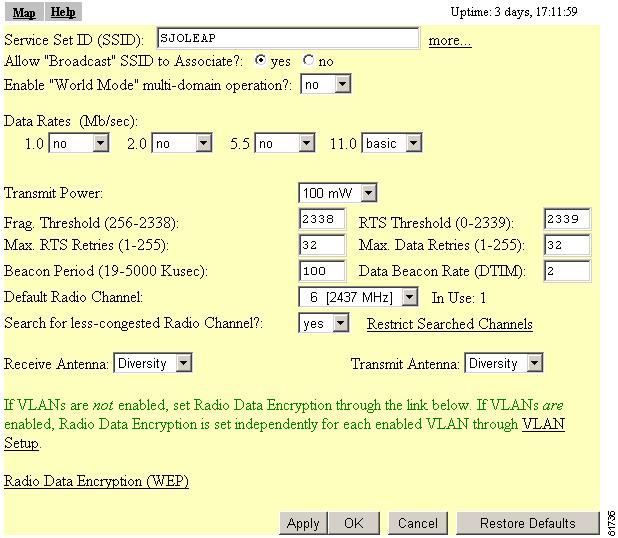
Basic Settings
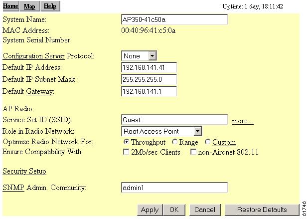
This section describes the basic settings on the Express Setup page. If you need to set up an access point quickly with a simple configuration, or change or update a basic setting, you can enter all the access point's essential settings for basic operation on the Express Setup page. Figure 3-1 shows the Express Setup page.
Figure 3-1 Express Setup Page
Follow this link path to reach the Express Setup page:
1.
On the Summary Status page, click Setup.
2.
Entering Basic Settings
The Express Setup page contains the following settings:
•
•
•
System Name
The system name appears in the titles of the management system pages and in the access point's Association Table page. The system name is not an essential setting, but it helps identify the access point on your network.
The access point's Media Access Control (MAC) address appears under the system name. The MAC address is a unique serial number permanently assigned to the access point's Ethernet controller. You cannot change the access point's MAC address.
Configuration Server Protocol
Set the Configuration Server Protocol to match the network's method of IP address assignment. Click the Configuration Server link to jump to the Boot Server Setup page, which contains detailed settings for configuring the access point to work with your network's BOOTP or DHCP servers for automatic assignment of IP addresses.
The Configuration Server Protocol drop-down menu contains the following options:
•
•
•
Click Configuration Server to access the Boot Server Setup page.
Default IP Address
Use this setting to assign or change the access point's IP address. If DHCP or BOOTP is not enabled for your network, the IP address you enter in this field is the access point's IP address. If DHCP or BOOTP is enabled, this field provides the IP address only if no server responds with an IP address for the access point.
Default IP Subnet Mask
Enter an IP subnet mask to identify the subnetwork so the IP address can be recognized on the LAN. If DHCP or BOOTP is not enabled, this field is the subnet mask. If DHCP or BOOTP is enabled, this field provides the subnet mask only if no server responds to the access point's DHCP or BOOTP request.
Default Gateway
Enter the IP address of your default internet gateway here. The entry 255.255.255.255 indicates no gateway. Clicking the Gateway link takes you to the Routing Setup page, which contains detailed settings for configuring the access point to communicate with the IP network routing system.
Click Gateway to access the Routing Setup page where you can configure a new default gateway network route. You can also remove an old routing configuration.
Radio Service Set ID (SSID)
An SSID is a unique identifier that client devices use to associate with the access point or a VLAN supported by the access point. The SSID helps client devices distinguish between multiple wireless networks and VLANs in the same vicinity and provides access to VLANs by wireless client devices. Several access points on a network or sub-network can share an SSID. You can configure up to 16 SSIDs on an access point. An SSID can be any alphanumeric, case-sensitive entry from 2 to 32 characters long.
Click more to go to the AP Radio Service Sets page where you can create additional SSIDs. From this page you can also edit an existing SSID or remove one from the system.
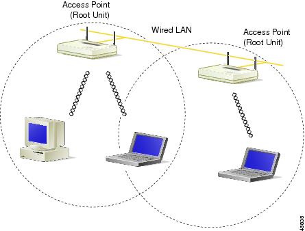
Role in Radio Network
Use this drop-down menu to select the role of the access point on your network. The menu contains the following options:
•
Figure 3-2 Root-Unit Access Points
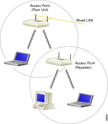
•
Figure 3-3 Repeater Access Point
•
Radio Network Optimization (Optimize Radio Network For)
You use this setting to select either pre configured settings for the access point radio or customized settings for the access point radio.
•
•
•
Radio Network Compatibility (Ensure Compatibility With)
You use this setting to automatically configure the access point to be compatible with other devices on your wireless LAN.
•
•
Security Setup Link
Clicking on this link takes you to the Security Setup page from which you can manage security issues on the access point. Settings on this page are covered in the "Setting Up Administrator Authorization" section.
SNMP Admin. Community
To use Simplified Network Management Protocol (SNMP), enter a community name here. This name automatically appears in the list of users authorized to view and make changes to the access point's management system, and SNMP is enabled.
Click SNMP to go to the SNMP Setup page, where you can edit other SNMP settings.
You can define other SNMP communities on the Administrator Authorization pages. See the "Setting Up Administrator Authorization" section for instructions on using the Administrator Authorization pages.
Radio Configuration
This section describes how to configure the access point's radio. You use the AP Radio pages in the management system to set the radio configuration. The radio pages include:
•
•
•
•
Entering Identity Information
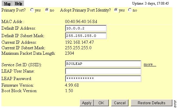
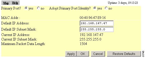
You use the AP Radio Identification page to enter basic locating and identity information for the access point radio. Figure 3-4 shows the AP Radio Identification page.
Figure 3-4 The AP Radio Identification Page
Follow this link path to reach the AP Radio Identification page:
1.
2.
Settings on the AP Radio Identification Page
The AP Radio Identification page contains the following settings:
The page also displays the access point's MAC address, its current IP address, its current IP subnet mask, its maximum packet data length, its firmware version, and its boot block version.
Primary Port Settings
Two options allow you to designate the access point's radio port as the Primary Port and select whether the radio port adopts or assumes the identity of the primary port.
•
•
Access points acting as root units adopt the primary port settings for the radio port. When you put an access point in standby mode, however, you select no for this setting. Some advanced wireless bridge configurations also require different identity settings for the radio port.
Default IP Address
Use this setting to assign an IP address for the radio port that is different from the access point's Ethernet IP address. During normal operation the radio port adopts the identity of the Ethernet port. When you put an access point in standby mode, however, you assign a different IP address to the radio port. Some advanced wireless bridge configurations also require a different IP address for the radio port.
Default IP Subnet Mask
Enter an IP subnet mask to identify the subnetwork so that the IP address can be recognized on the LAN. If DHCP or BOOTP is not enabled, this field is the subnet mask. If DHCP or BOOTP is enabled, this field provides the subnet mask only if no server responds to the access point's request.
The current IP subnet mask displayed under the setting shows the IP subnet mask currently assigned to the access point. This is the same subnet mask as the default subnet mask unless DHCP or BOOTP is enabled. If DHCP or BOOTP is enabled, this is the subnet mask used by the DHCP or BOOTP server.
You can also enter this setting on the Express Setup page.
Service Set ID (SSID)
An SSID is a unique identifier that client devices use to associate with the access point or a VLAN supported by the access point. SSIDs help client devices distinguish between multiple wireless networks and VLANs in the same vicinity and provide access to VLANs by wireless client devices. Several access points on a network or sub-network can share an SSID. You can configure up to 16 SSIDs on an access point. An SSID can be any alphanumeric, case-sensitive entry from 2 to 32 characters long.
Click more to go to the AP Radio Service Sets page where you can create additional SSIDs. From this page you can also edit an existing SSID or remove one from the system.
You can also enter this setting on the Express Setup page.
LEAP User Name
Use this field if the radio is set up as a repeater and authenticates to the network using LEAP. When the radio authenticates using LEAP, the access point sends this user name to the authentication server.
Follow the steps in the "Setting Up a Repeater Access Point as a LEAP Client" section to set up the radio as a LEAP client.
LEAP Password
Use this field if the radio is set up as a repeater and authenticates to the network using LEAP. When the radio authenticates using LEAP, the access point uses this password for authentication.
Follow the steps in the "Setting Up a Repeater Access Point as a LEAP Client" section to set up the radio as a LEAP client.
Entering Radio Hardware Information
You use the AP Radio Hardware page to assign settings related to the access point's radio hardware. Figure 3-5 shows the AP Radio Hardware page.
Figure 3-5 The AP Radio Hardware Page
Follow this link path to reach the AP Radio Hardware page:
1.
2.
Settings on the AP Radio Hardware Page
The AP Radio Hardware page contains the following settings:
•
•
•
The AP Radio Hardware page also contains a link to the AP Radio Data Encryption Setup and VLAN Setup pages, which you can use to configure the radio's data encryption. Which link you choose depends on whether you are using VLANs. If VLANs are not enabled, use the Radio Data Encryption (WEP) link to configure the radio's data encryption settings. If VLANs are enabled, use the VLAN Setup link to configure the radio data encryption.
Service Set ID (SSID)
An SSID is a unique identifier that client devices use to associate with the access point or a VLAN supported by the access point. The SSID helps client devices distinguish between multiple wireless networks and VLANs in the same vicinity and provides access to VLANs by wireless client devices. Several access points on a network or sub-network can share an SSID. You can configure up to 16 separate SSIDs. The SSID can be any alphanumeric, case-sensitive entry from 2 to 32 characters long.
Click more to go to the AP Radio Service Sets page where you can create additional SSIDs. From this page you can also edit an existing SSID or remove one from the system.
You can also enter this setting on the Express Setup and AP Radio Identification pages.
Allow Broadcast SSID to Associate?
You use this setting to choose whether devices that do not specify an SSID (devices that are "broadcasting" in search of an access point to associate with) are allowed to associate with the access point.
•
•
Enable World Mode
When you select yes from the world-mode drop-down menu, the access point adds channel carrier set information to its beacon. Client devices with world-mode enabled receive the carrier set information and adjust their settings automatically.
Data Rates
You use the data rate settings to choose the data rates the access point uses for data transmission. The rates are expressed in megabits per second.
The access point always attempts to transmit at the highest data rate set to Basic. If there are obstacles or interference, the access point steps down to the highest rate that allows data transmission. For each of four rates (1, 2, 5.5, and 11 megabits per second), a drop-down menu lists three options:
•
•
•
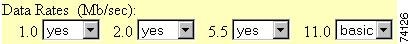
You can use the Data Rate settings to set up an access point to serve client devices operating at specific data rates. For example, to set up the access point for 11 megabits per second (Mbps) service only, select Basic for 11 and select Yes for the other data rates. Figure 3-6 shows the Data Rates set up for 11-Mbps service only.
Figure 3-6 Data Rate Settings for 11 Mbps Service Only
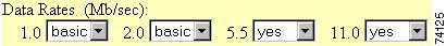
To set up the access point to serve only client devices operating at 1 and 2 Mbps, select Basic for 1 and 2 and set the rest of the data rates to Yes. Figure 3-7 shows the Data Rates set up for 1- and 2-Mbps service only.
Figure 3-7 Data Rate Settings for 1- and 2-Mbps Service Only
The Optimize Radio Network For setting on the Express Setup page selects the data rate settings automatically. When you select Optimize Radio Network For Throughput on the Express Setup page, all four data rates are set to basic. When you select Optimize Radio Network For Range on the Express Setup page, the 1.0 data rate is set to basic, and the other data rates are set to Yes.
Transmit Power
This setting determines the power level of radio transmission.
Note
To reduce interference or to conserve power, select a lower power setting. The settings in the drop-down menu on 350 series access points include 1, 5, 20, 50, and 100 milliwatts. The settings in the drop-down menu on 340 series access points include 1, 5, and 30 milliwatts.
Note
Frag. Threshold
This setting determines the size at which packets are fragmented (sent as several pieces instead of as one block). Enter a setting ranging from 256 to 2338 bytes. Use a low setting in areas where communication is poor or where there is a great deal of radio interference.
RTS Threshold
This setting determines the packet size at which the access point issues a request to send (RTS) before sending the packet. A low RTS Threshold setting can be useful in areas where many client devices are associating with the access point, or in areas where the clients are far apart and can detect only the access point and not each other. Enter a setting ranging from 0 to 2339 bytes.
Max. RTS Retries
The maximum number of times the access point issues an RTS before stopping the attempt to send the packet through the radio. Enter a value from 1 to 128.
Max. Data Retries
The maximum number of attempts the access point makes to send a packet before giving up and dropping the packet.
Beacon Period
The amount of time between beacons in Kilomicroseconds. One Kmsec equals 1,024 microseconds.
Data Beacon Rate (DTIM)
This setting, always a multiple of the beacon period, determines how often the beacon contains a delivery traffic indication message (DTIM). The DTIM tells power-save client devices that a packet is waiting for them.
If the beacon period is set at 100, its default setting, and the data beacon rate is set at 2, its default setting, then the access point sends a beacon containing a DTIM every 200 Kmsecs. One Kmsec equals 1,024 microseconds.
Default Radio Channel
The factory setting for Cisco wireless LAN systems is Radio Channel 6 transmitting at 2437 MHz. To overcome an interference problem, other channel settings are available from the drop-down menu of 11 channels ranging from 2412 to 2462 MHz.
Each channel covers 22 MHz. The bandwidth for channels 1, 6, and 11 does not overlap, so you can set up multiple access points in the same vicinity without causing interference.
Note
Search for Less-Congested Radio Channel
When you select yes from the Search for less-congested radio channel drop-down menu, the access point scans for the radio channel that is least busy and selects that channel for use. The access point scans at power-up and when the radio settings are changed.
Note
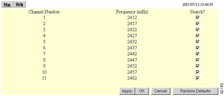
Restrict Searched Channels
Click Restrict Searched Channels to limit the channels that the access point scans when Search for less-congested radio channel is enabled. The AP Radio Restrict Searched Channels page appears when you click Restrict Searched Channels. Figure 3-8 shows the AP Radio Restrict Searched Channels page.
Figure 3-8 AP Radio Restrict Searched Channels Page
The page lists all the channels in the access point's regulatory domain. Click the Search check boxes beside the channels to include or exclude channels in the scan for less-congested channels. All the channels are included in the scan by default.
Receive Antenna and Transmit Antenna
Drop-down menus for the receive and transmit antennas offer three options:
•
•
•
Note
Entering Advanced Configuration Information
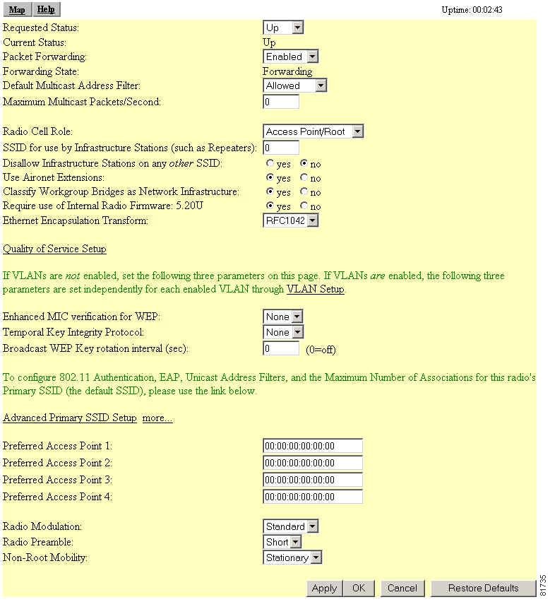
Use the AP Radio Advanced page to assign special configuration settings for the access point's radio. Figure 3-9 shows the AP Radio Advanced page.
Figure 3-9 AP Radio Advanced Page
Follow this link path to reach the AP Radio Advanced page:
1.
2.
Settings on the AP Radio Advanced Page
The AP Radio Advanced page contains the following settings:
•
•
•
•
•
•
•
•
•
•
•
•
Requested Status
This setting is useful for troubleshooting problems on your network. Up, the default setting, turns the radio on for normal operation. Down turns the access point's radio off.
Current Status
The Current Status line under the setting displays the current status of the radio port. This field can also display Error, meaning the port is operating but is in an error condition.
Packet Forwarding
This setting is always set to Enabled for normal operation. For troubleshooting, you might want to set packet forwarding to Disabled, which prevents data from moving between the Ethernet and the radio.
Forwarding State
The Forwarding State line under the setting displays the current forwarding state. For normal access point operation, the forwarding state is Forwarding. Four other states are possible:
•
•
•
•
Default Multicast Address Filters
MAC address filters allow or disallow the forwarding of multicast packets sent to specific MAC addresses. You can create a filter that passes traffic to all MAC addresses except those you specify, or you can create a filter that blocks traffic to all MAC addresses except those you specify. Read the "Creating a MAC Address Filter" section for complete instructions on setting up MAC address filters.
The drop-down menus for multicast address filters contain two options:
•
•
Note
Maximum Multicast Packets/Second
Use this setting to control the number of multicast packets that can pass through the radio port each second. If you enter 0, the access point passes an unlimited number of multicast packets. If you enter a number other than 0, the device passes only that number of multicast packets per second.
Radio Cell Role
Use this drop-down menu to select the function of the access point's radio within its radio coverage area (cell). This setting determines how the access point's radio interacts with other wireless devices. The menu contains the following options:
•
•
•
SSID for use by Infrastructure Stations (such as Repeaters)
Identifies the SSID to be used by repeaters and workgroup bridges to associate to the access point. It is also the SSID used by a non-root bridge to associate to a root bridge. This SSID should be mapped to the native VLAN ID in order to facilitate communications between infrastructure devices and a non-root access point or bridge.
Disallow Infrastructure Stations on any other SSID
Prevents repeaters or workgroup bridges from associating to SSIDs other than the infrastructure SSID. The default setting is No, so to invoke this condition, you must change the setting to Yes.
Use Aironet Extensions
Select yes or no to use Cisco Aironet 802.11 extensions. This setting must be set to yes (the default setting) to enable these features:
•
•
•
•
The extensions also improve the access point's ability to understand the capabilities of Cisco Aironet client devices associated with the access point.
Note
Classify Workgroup Bridges as Network Infrastructure
Select no to allow more than 20 Cisco Aironet Workgroup Bridges to associate to the access point. The default setting, yes, limits the number of workgroup bridges that can associate to the access point to 20 or less.
The Reliable multicast messages from the access point to workgroup bridges setting limits reliable delivery of multicast messages to approximately 20 Cisco Aironet Workgroup Bridges that are associated to the access point. The default setting, disabled, reduces the reliability of multicast delivery to allow more workgroup bridges to associate to the access point.
Access points and bridges normally treat workgroup bridges not as client devices but as infrastructure devices, like access points or bridges. Treating a workgroup bridge as an infrastructure device means that the access point reliably delivers multicast packets, including Address Resolution Protocol (ARP) packets, to the workgroup bridge.
The performance cost of reliable multicast delivery—duplication of each multicast packet sent to each workgroup bridge—limits the number of infrastructure devices, including workgroup bridges, that can associate to the access point. To increase beyond 20 the number of workgroup bridges that can maintain a radio link to the access point, the access point must reduce the delivery reliability of multicast packets to workgroup bridges. With reduced reliability, the access point cannot confirm whether multicast packets reach the intended workgroup bridge, so workgroup bridges at the edge of the access point's coverage area might lose IP connectivity. When you treat workgroup bridges as client devices, you increase performance but reduce reliability.
Note
A Cisco Aironet Workgroup Bridge provides a wireless LAN connection for up to eight Ethernet-enabled devices. Refer to the "Overview" section on page 1-2 of the Cisco Aironet Workgroup Bridge Software Configuration Guide for a description of workgroup bridges.
Require Use of Radio Firmware x.xx
This setting affects the firmware upgrade process when you load new firmware for the access point. Select yes to force the radio firmware to be upgraded to a firmware version compatible with the current version of the management system. Select no to exempt the current radio firmware from firmware upgrades.
Ethernet Encapsulation Transform
Choose 802.1H or RFC1042 to set the Ethernet encapsulation type. Data packets that are not 802.2 packets must be formatted to 802.2 using 802.1H or RFC1042. Cisco Aironet equipment uses 802.1H because it provides optimum interoperability.
•
•
Quality of Service Setup Link
Clicking on the Quality of Service (QoS) Setup link accesses the AP Radio Quality of Service page. Use this page to configure the radio's QoS setup and priorities. Read the "Quality of Service Support" section for a description of QoS. See the "QoS Configuration" section to set up QoS.
VLAN Setup Link
Clicking the VLAN Setup link accesses the VLAN Setup page. Use this page to configure, add, edit, and remove VLANs associated with your access point. Read the "VLAN Support" section for a description of VLANs. Go to the "Creating and Configuring VLANs on the Access Point" section to set up VLANs.
Enhanced MIC verification for WEP
This setting enables Message Integrity Check (MIC), a security feature that protects your WEP keys by preventing attacks on encrypted packets called bit-flip attacks. During a bit-flip attack, an intruder intercepts an encrypted message, alters it slightly, and retransmits it, and the receiver accepts the retransmitted message as legitimate. The MIC, implemented on both the access point and all associated client devices, adds a few bytes to each packet to make the packets tamper-proof. Select MMH from the drop-down menu and click Apply to enable MIC.
Note
Note
Temporal Key Integrity Protocol
This setting enables the temporal key integrity protocol (TKIP, also known as WEP key hashing), which defends against an attack on WEP in which the intruder uses the unencrypted initialization vector (IV) in encrypted packets to calculate the WEP key. WEP key hashing removes the predictability that an intruder relies on to determine the WEP key by exploiting IVs. Select Cisco from the drop-down menu and click Apply to enable TKIP.
Note
Note
Broadcast WEP Key rotation interval (sec)
This option enables broadcast key rotation by setting a key rotation interval. With broadcast, or multicast, WEP key rotation enabled, the access point provides a dynamic broadcast WEP key and changes it at the interval you select. Broadcast key rotation is an excellent alternative to TKIP if your wireless LAN supports wireless client devices that are not Cisco devices or that cannot be upgraded to the latest firmware for Cisco client devices.
To enable broadcast key rotation, enter the rotation interval in seconds in the Broadcast WEP Key rotation interval entry field. If you enter 900, for example, the access point sends a new broadcast WEP key to all associated client devices every 15 minutes. To disable broadcast WEP key rotation, enter 0.
Note
Advanced Primary SSID Setup Link
Go to this link to configure 802.11 authentication, EAP, Unicast address filters, and the maximum number of associations for the radio's primary SSID.
This link takes you to the AP Radio Primary SSID page, from which you can configure the primary SSID settings. From this page, you configure IEEE 802.11x authentication, EAP, unicast address filters, and the maximum number of associations for the radio's primary SSID.
The more link takes you to the AP Radio Service Set Setup page.
Preferred Access Points
You use these fields to set up a chain of repeater access points (access points without an Ethernet connection; see Figure 3-3). Repeater access points function best when they associate with specific access points connected to the wired LAN. You use these fields to specify the access points that provide the most efficient data transmission link for the repeater.
If this access point is a repeater, type the MAC address of one or more root-unit access points with which you want this access point to associate. With MAC addresses in these fields, the repeater access point always tries to associate with the specified access points instead of with other less-efficient access points.
If the Adopt Primary Port Identity setting on the specified access point's Radio Identification page is set to no, you should enter the radio's MAC address as it appears on the Radio Identification page. Usually, however, the Adopt Primary Port Identity setting is set to yes, and you can enter the specified access point's primary MAC address, which appears on the Express Setup page.
For complete instructions on setting up repeater access points, see the "Setting Up a Repeater Access Point" section.
Radio Modulation
Select Standard or MOK for the radio modulation the access point uses.
•
•
Radio Preamble
The radio preamble is a section of data at the head of a packet that contains information the access point and client devices need when sending and receiving packets. The drop-down menu allows you to select a long or short radio preamble:
•
•
Non-Root Mobility
This setting applies mainly to repeater access points that you intend to use in a roaming environment. The drop-down menu allows you to select either stationary or mobile settings:
•
•
Ethernet Configuration
This section describes how to configure the access point's Ethernet port. Use the Ethernet pages in the management system to set the Ethernet port configuration. The Ethernet pages include:
•
•
•
•
Entering Identity Information
You use the Ethernet Identification page to enter basic locating and identity information for the access point's Ethernet port. Figure 3-10 shows the Ethernet Identification page.
Figure 3-10 The Ethernet Identification Page
Follow this link path to reach the Ethernet Identification page:
1.
2.
Settings on the Ethernet Identification Page
The Ethernet Identification page contains the following settings:
The page also displays the access point's MAC address, its current IP address, its current IP subnet mask, and the maximum packet data length allowed.
Primary Port Settings
Two options allow you to designate the access point's Ethernet port as the Primary Port and select whether the Ethernet port adopts or assumes the identity of the primary port.
•
•
Some advanced bridge configurations require different settings for the Ethernet and radio ports.
Default IP Address
Use this setting to assign or change the access point's IP address. If DHCP or BOOTP is not enabled for your network, the IP address you enter in this field is the access point's IP address. If DHCP or BOOTP is enabled, this field provides the IP address only if no server responds with an IP address for the access point.
The current IP address displayed under the Default IP Address setting shows the IP address currently assigned to the access point. This is the same address as the default IP address unless DHCP or BOOTP is enabled. If DHCP or BOOTP is enabled, this field displays the IP address that has been dynamically assigned to the device for the duration of its session on the network, and it might be different than the default IP address.
You can also enter this setting on the Express Setup and AP Radio Identification pages.
Default IP Subnet Mask
Enter an IP subnet mask to identify the subnetwork so the IP address can be recognized on the LAN. If DHCP or BOOTP is not enabled, this field is the subnet mask. If DHCP or BOOTP is enabled, this field provides the subnet mask only if no server responds to the access point's request.
The current IP subnet mask displayed under the setting shows the IP subnet mask currently assigned to the access point. This is the same subnet mask as the default subnet mask unless DHCP or BOOTP is enabled. If DHCP or BOOTP is enabled, this is the subnet mask used by the server.
You can also enter this setting on the Express Setup and AP Radio Identification pages.
Entering Ethernet Hardware Information
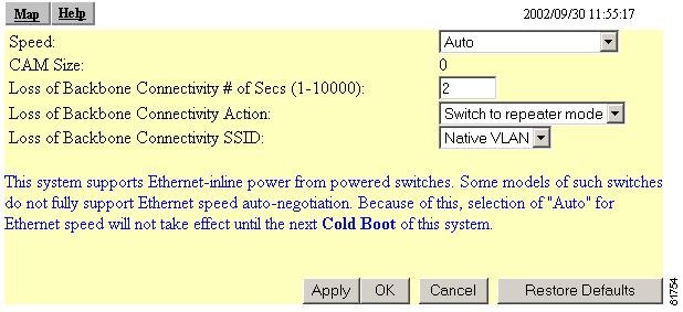
You use the Ethernet Hardware page to select the connector type, connection speed, and duplex setting used by the access point's Ethernet port. Figure 3-11 shows the Ethernet Hardware page.
Figure 3-11 The Ethernet Hardware Page
Follow this link path to reach the Ethernet Hardware page:
1.
2.
Settings on the Ethernet Hardware Page
The Ethernet Hardware page contains the following settings:
•
•
•
The page also displays content addressable memory (CAM) size (not a defined feature in this release) and contains a note indicating the access point supports Ethernet inline power from powered switches.
Speed
The Speed drop-down menu lists five options for the type of connector, connection speed, and duplex setting used by the port. The option you select must match the actual connector type, speed, and duplex settings used to link the port with the wired network.
The default setting, Auto, is best for most networks because the best connection speed and duplex setting are automatically negotiated between the wired LAN and the access point. If you use a setting other than Auto, make sure the hub, switch, or router to which the access point is connected supports your selection.
•
Note
•
•
•
•
Loss of Backbone Connectivity # of Secs (1-10000)
This setting specifies the amount of time the access point has before taking action when it detects a loss of backbone connectivity (such as a loss of Ethernet link and no active trunks available on its radio). The action the access point takes is specified in the Loss of Backbone Connectivity Action setting, described in the next section.
Loss of Backbone Connectivity Action
This setting determines what action the access point takes when a loss of backbone connectivity occurs after the time specified in the previous setting. The following actions can be taken :
•
•
•
•
Loss of Backbone Connectivity SSID
This setting specifies the SSID used by the access point if the Loss of Backbone Connectivity Action setting is set as Restrict to SSID and backbone connectivity is lost for longer than the time specified in the Loss of Backbone Connectivity: Number of Seconds setting.
The setting also defines an administrator-only SSID an administrator uses to communicate with the access point for diagnostic and failure-recovery purposes.
If VLANs are active on the access point, the SSID names are displayed in the Loss of Backbone Connectivity SSID field.
Note
Entering Advanced Configuration Information
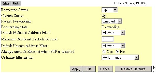
You use the Ethernet Advanced page to assign special configuration settings for the access point's Ethernet port. Figure 3-12 shows the Ethernet Advanced page.
Figure 3-12 The Ethernet Advanced Page
Follow this link path to reach the Ethernet Advanced page:
1.
2.
Settings on the Ethernet Advanced Page
The Ethernet Advanced page contains the following settings:
•
•
•
The page also displays the current status of the Ethernet port and its forwarding state. The current status displays either up or down and can also display Error if the port is in an error condition.
The forwarding state displays the port's current forwarding state. The state for normal operation is Forwarding. Four other settings are possible:
•
•
•
•
Requested Status
This setting is useful for troubleshooting problems on your network. Up, the default setting, enables the Ethernet port for normal operation. Down disables the access point's Ethernet port.
The Current Status line under the setting displays the current status of the Ethernet port. This field can also display Error, meaning the port is in an error condition.
Packet Forwarding
This setting is always set to Enabled for normal operation. For troubleshooting, you might want to set packet forwarding to Disabled, which prevents data from moving between the Ethernet and the radio.
The Forwarding State line under the setting displays the current forwarding state. The state for normal operation is Forwarding. Four other settings are possible:
•
•
•
•
Default Unicast and Multicast Address Filters
MAC address filters allow or disallow the forwarding of unicast and multicast packets sent to specific MAC addresses. You can create a filter that passes traffic to all MAC addresses except those you specify, or you can create a filter that blocks traffic to all MAC addresses except those you specify. Read the "MAC Address Filtering" section for complete instructions on setting up MAC address filters.
Unicast packets are addressed to just one device on the network. Multicast packets are addressed to multiple devices on the network.
The drop-down menus for unicast and multicast address filters contain two options:
•
•
Note
Note
Maximum Multicast Packets/Second
Use this setting to control the number of multicast packets that can pass through the Ethernet port each second. If you enter 0, the access point passes an unlimited number of multicast packets. If you enter a number other than 0, the device passes only that number of multicast packets per second.
Default Unicast Address Filter
Use this setting to specify whether the default unicast filter is allowed or disallowed.
Optimize Ethernet for
Use this setting to specify how you want the Ethernet link to perform. You have two options: performance (the default setting) and statistics collection. The performance option causes limited per station statistics to be returned. The statistics option allows full statistics in more detail to be returned.
Selecting either results in a compromise. However, on a well-designed network, this compromise is virtually unnoticed.