-
Cisco MediaSense Solution Reference Network Design Guide, Release 10.0(1)
-
Product overview
-
Characteristics and features
-
Codecs supported
-
Metadata database and the MediaSense API
-
Disk space management
-
System resiliency and overload throttling
-
MediaSense-specific deployment models
-
Solution environment
-
High availability
-
Security
-
Reporting and call correlation
-
Serviceability and administration
-
Design guidance
-
Compatibility matrix
-
Scalability and sizing
-
Index
-
 Feedback
Contents
- Solution environment
- General flow - Unified Communications Manager calls
- General flow - CUBE calls
- General flow - streaming media
- Solution-level deployment models
- Unified Communications Manager deployments
- Basic CUBE deployment
- CUBE deployments with CVP
- Additional deployment options and considerations
- When to use CUBE and when to use a built-in bridge (BiB)
- Configuration requirements for other solution components
Solution environment
Solution overview and call flows
The following diagrams depict the MediaSense solution environment for Unified Communications Manager deployments and for CUBE deployments:
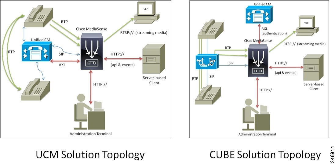
Though these diagrams each show only one MediaSense server and one Unified Communications Manager server or CUBE, each should be considered as a cluster of such devices. That is, one cluster of MediaSense servers interacts with one cluster of Unified Communications Manager servers or with one or more CUBE devices.
For Unified Communications Manager deployments, there is no concept of a hierarchy of recording servers. SIP Trunks should be configured to point to all MediaSense servers.
For CUBE deployments, recording dial peers should be configured to point to one or two of the MediaSense servers (preferably avoiding the primary and secondary). The High availability section discusses this in more detail.
UCS-E deployments are built with exactly the same topology. Physically, a UCS-E module is a blade inserted into a router rather than a separate rack-mounted server; but logically it functions no differently within the solution environment than does a rack-mounted server. A UCS-E-based MediaSense cluster can even record calls that are forked from Unified Communications Manager phones.
Notice that the CUBE solution topology includes a Unified Communications Manager device. This is used only for authentication purposes and has no role in call flow.
- General flow - Unified Communications Manager calls
- General flow - CUBE calls
- General flow - streaming media
- Solution-level deployment models
- Configuration requirements for other solution components
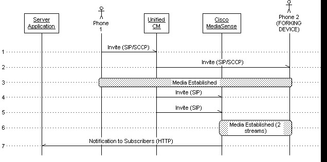
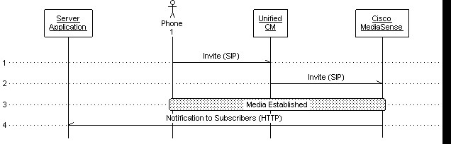
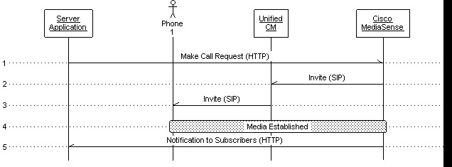
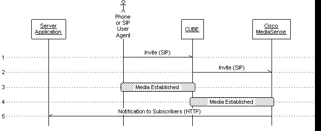
General flow - Unified Communications Manager calls
For compliance recording applications, call recordings are initiated via a pair of SIP invitations from Unified Communications Manager to MediaSense after the initial call has been established between two parties. Unified Communications Manager is involved in the call setup but media flows to MediaSense from one of the phones—not from Unified Communications Manager.
Inbound blog recordings are initiated in a similar way. A SIP invitation is sent from Unified Communications Manager to MediaSense. Outbound blog recordings are initiated with an API request ("startRecording") to MediaSense, which triggers an outbound SIP invitation from MediaSense to Unified Communications Manager. In all cases, the processing of the invitation results in one or more RTP media streams being established between the phone being recorded and MediaSense. These call flows are depicted in the following figures.
NoteThese figures are for illustration purposes only and do not show the detailed message flow.
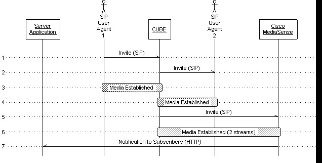
General flow - CUBE calls
In CUBE recording, applications have similar flows, but there are important differences. Call recordings are initiated with a single SIP invitation from CUBE to MediaSense containing two "m" lines, as opposed to two separate invitations that each contain one "m" line. As with Unified Communications Manager, the invitation is sent only after the initial call has been established between two parties. However, the media that flows to MediaSense comes from CUBE, not from one of the endpoints.
Inbound blog recordings are initiated by directly dialing a call from an endpoint, through CUBE, to MediaSense. In all cases, the processing of the invitation to MediaSense results in one or more RTP media streams being established between the CUBE and MediaSense. These call flows are depicted in the following figures.
NoteThese figures are for illustration purposes only and do not show the detailed message flow. Also, outbound blog recordings are not supported with CUBE deployments.
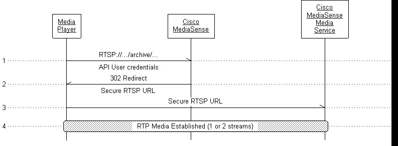
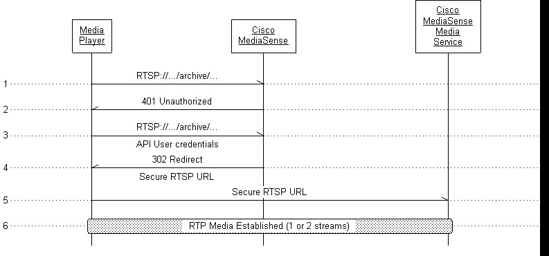
General flow - streaming media
Live monitoring happens when a workstation running a streaming media player sends an RTSP:// URI to MediaSense specifying an active media address and an RTP media stream is established between MediaSense and the player. This stream is actually a copy of one of the streams that MediaSense is receiving from the phone; the media does not come from the disk.
Playback is initiated when a workstation running a streaming media player sends an RTSP:// URI to MediaSense specifying an "archive" media address. The resulting media stream between MediaSense and the player is read from the disk.
Live monitoring and playback call flows are illustrated below (showing how authentication takes place, but not showing the detailed message flow). The MediaSense Media Service is the software component within each node that is responsible for handling streaming media.
The MediaSense API is accessed from either a server-based or a browser-based client. Server-based clients may subscribe for asynchronous events as well.
Solution-level deployment models
This section summarizes the many ways in which MediaSense can be deployed as part of a solution.
- Unified Communications Manager deployments
- Basic CUBE deployment
- CUBE deployments with CVP
- Additional deployment options and considerations
- When to use CUBE and when to use a built-in bridge (BiB)
Unified Communications Manager deployments
These deployment models cover scenarios in which Cisco IP phones are configured for media forking. Two versions are covered:
From the perspective of MediaSense, there is actually no difference between the two basic Unified Communications Manager versions. In both cases, media forked by a phone is sent to the recording device where the forked streams are captured. They are distinguished here because there is a significant difference in their behavior at the solution level.
Unified Communications Manager deployment - internal-to-external
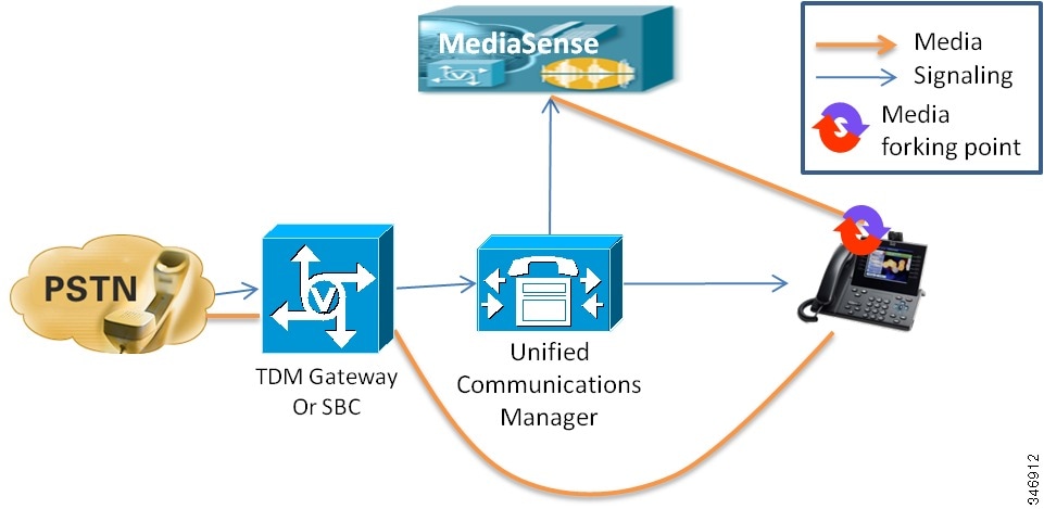
The preceding diagram shows a basic Unified Communications Manager deployment where calls with parties who are outside the enterprise are recorded. This applies to both inbound and outbound calls, as long as the inside phone is configured with an appropriate recording profile.
Once the connection is established from a signaling perspective, media flows directly from the forking phone to the recording server.
If the call is transferred away from this phone, the recording session ends. Only if the phone which takes up the call is configured for recording will the next segment of the call be captured.
Unified Communications Manager deployment - internal-to-internal
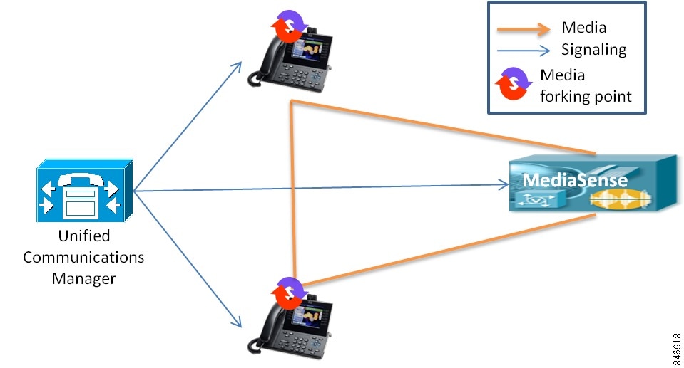
This diagram shows a basic Unified Communications Manager deployment where calls are with parties who are inside the enterprise. One of the phones must be configured for recording. If both phones are configured for recording, then two separate recording sessions are captured.
Unified SME deployment
At this time, MediaSense does not support SME deployments in the general sense. In an SME environment, all the phones that are to be recorded by a specific MediaSense cluster must be part of the same SME leaf cluster. If phones from different leaf clusters need to be recorded, then separate and independent MediaSense clusters must be deployed, as shown in this diagram.

The preceding diagram demonstrates how MediaSense clusters must be connected to SME leaf clusters, not to the SME manager cluster. The diagram also shows the leaf clusters connecting to separate MediaSense clusters. That is a supported arrangement, but it is also acceptable for them to share one or more MediaSense clusters.
Basic CUBE deployment
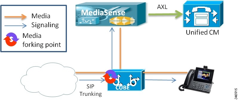
The preceding diagram shows a very basic CUBE deployment where calls arrive on a SIP Trunk from the PSTN and are connected to a SIP phone inside the enterprise. The media forking is performed by the CUBE device using a recorder profile configuration that is attached to one or more dial peers.
When a call passes through CUBE (or any Cisco router for that matter), it matches two dial peers - one at the point where the call enters the CUBE, and one at the point where it exits. From the CUBE system perspective, these are known as the inbound and outbound dial peers. These terms are relative to the direction of the call. On an inbound call, the inbound dial peer is the one that represents the outside of the enterprise and the outbound dial peer represents the inside of the enterprise. The assignment is reversed for an outbound call. In this document, we use the terms inside and outside dial peers to represent the inside and the outside of the enterprise respectively.
Although there are a few exceptions, it is a best practice is to apply the recording profile to the outside dial peer—the inbound dial peer for inbound calls and the outbound dial peer for outbound calls. This is because the external leg of the call is typically quite stable, whereas the internal leg is often subject to complex call manipulations including various kinds of consults, conferences, and transfers. If any of those operations cause the CUBE to trigger a new dial peer match, the recording session may be terminated prematurely. (If such an operation causes the prevailing codec to be changed, the recording session is terminated and a new one is initiated.)
This diagram also shows a Unified Communications Manager component. Though currently required for CUBE deployments, Unified Communications Manager does not perform any call signaling, media, or record keeping. A single Unified Communications Manager server is required to manage and authenticate MediaSense API users. It can be any existing or specially installed Unified Communications Manager server on Release 8.5(1) or later. Ideally, the server selected should be one that is not itself loaded with calls.
The Unified Communications Manager server is omitted from the remaining CUBE deployment model diagrams since it plays no part in call handling.
The basic CUBE deployment is unlikely to ever be used in a production environment. More typically, a Unified Communications Manager, other Private Branch Exchange (PBX), or Automatic Call distributor (ACD) would be attached to the internal side of the CUBE and phones would be attached to that rather than to the CUBE directly. However, all CUBE deployments contain this configuration at their core. From the strict perspective of CUBE and MediaSense, all the other models are no different from this one.
Basic CUBE deployment with various PBXs
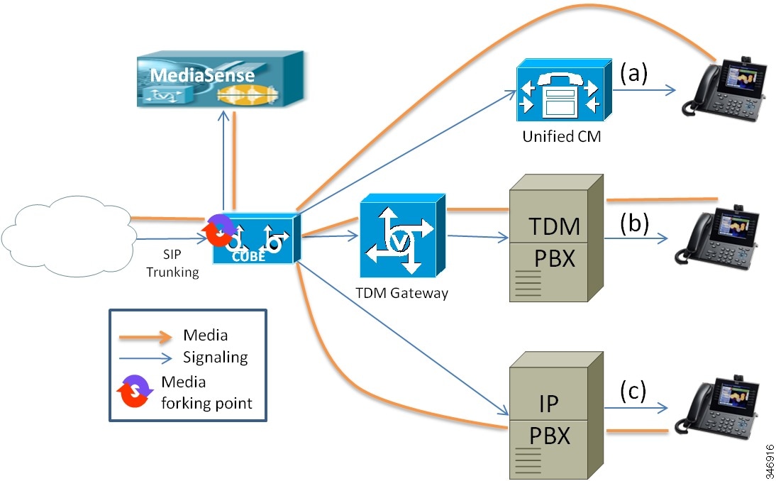
One of the great advantages of using CUBE to fork media is its ability to capture the entire conversation from the caller perspective, no matter where the call goes inside the enterprise. This includes contact center agents, non-contact center personnel, IVR systems, and even users on non-Cisco ACD and PBX systems.
The preceding diagram shows three ways that MediaSense and CUBE may be deployed in a heterogeneous enterprise environment. Any given call might experience one or a combination of these flows and the entire caller experience will be recorded. Additional combinations are possible as well; for example a call may be handled by an IP-based or TDM-based IVR system.
CUBE deployment variation using TDM ingress
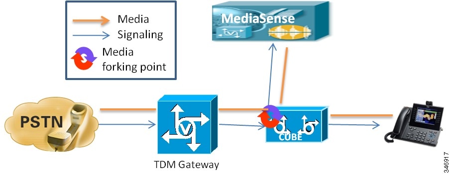
In order to fork media, CUBE must be dealing with a SIP to SIP call. If calls are arriving by TDM, then a separate TDM gateway is provisioned as shown in the diagram above. Forking is then be configured as usual on the outside dial peer of the CUBE.
If your application is designed to transmit DTMF signals to the PSTN, such as to perform PSTN-controlled transfers (also known as *8 Transfer Connect), then you must ensure that both the CUBE and the TDM gateway are configured to use the same method for DTMF signaling. You can do so by adding the same "dtmf-relay" configuration to the connecting dial peers in both devices. Relay type "rtp-nte" is the most standard, preferred method. The dial peer going to CVP should also be configured with rtp-nte.
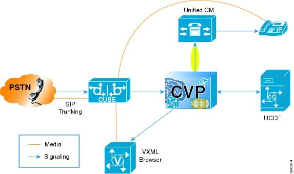
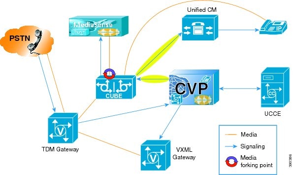
CUBE deployments with CVP
When CUBE is connect to Customer Voice Portal (CVP), MediaSense can be used to record calls in a contact center. The following subsections describe these models:
CVP deployments typically involve a VXML function and optionally a TDM to IP conversion function. CVP deployment recommendations sometimes provide for combining those two functions on the same ISR router. There are also CVP deployments that involve incoming SIP Trunks rather than TDM lines. These deployments may use CUBE routers and they may also host the VXML function. CVP also includes an optional component—Call Survivability—that allows branch routers to continue to provide a degraded level of service to callers even if the WAN connection between the router and CVP is out of service. This component is implemented as a TCL-IVR application installed directly on each gateway and associated with a dial peer.
CVP deployments with CUBE media forking must manage up to four distinct activities:
Some of these activities conflict with each other at the dial peer level, and certain steps must be taken in order to ensure that they interact well together. For example, you must not configure both media forking and a TCL or VXML application on the same dial peer. Each activity uses resources on the router, so they must all be taken into consideration for sizing. It is technically possible to configure one router to provide all four capabilities and in low call volume scenarios it is fine to do so. But as call volume rises, you must move either VXML browsing or media forking to a separate device. These two functions must not be co-located.
The function to isolate depends on your needs. VXML takes the bulk of router resources (especially if Automatic Speech Recognition is being used) and its sizing calculation is based on a different (usually smaller) quantity of calls than are the other activities. For the convenience and simplicity of sizing calculations, isolating VXML is a good choice.
However, if your intent is to capture only the agent part of the call in your recordings (see "Omitting the VRU Segment from a Recording") , then the configuration required to do so is far simpler if you perform media forking on a separate router. This has a further advantage in that co-locating TDM-to-IP, Call Survivability, and VXML browsing on a single router is the most common configuration for branch offices in a CVP deployment.
In multi-site ingress deployments, especially branch office deployments, you must use a combination of "Significant Digits" and "Send To Originator" functions in CVP's call routing configuration in order to prevent calls from inadvertently traversing a WAN link.
See the CVP documentation for more information about these techniques.
Note
During normal processing of SIP messages, CVP inserts arbitrary data into the SIP content as a multi-part body. This format is currently not supported by MediaSense, nor is the content of interest to MediaSense. The recording dial peer in CUBE must be configured to prevent this content from being forwarded to MediaSense by adding the command "signaling forward none" to the recording dial peer.
If the same physical router is being used for both MediaSense and Unified CVP, it must be running a version of IOS which has been qualified by both products.
Except in the simplest of scenarios, contact the ISR sales team for capacity planning.
CUBE deployments with Unified CVP - SIP trunks, no survivability
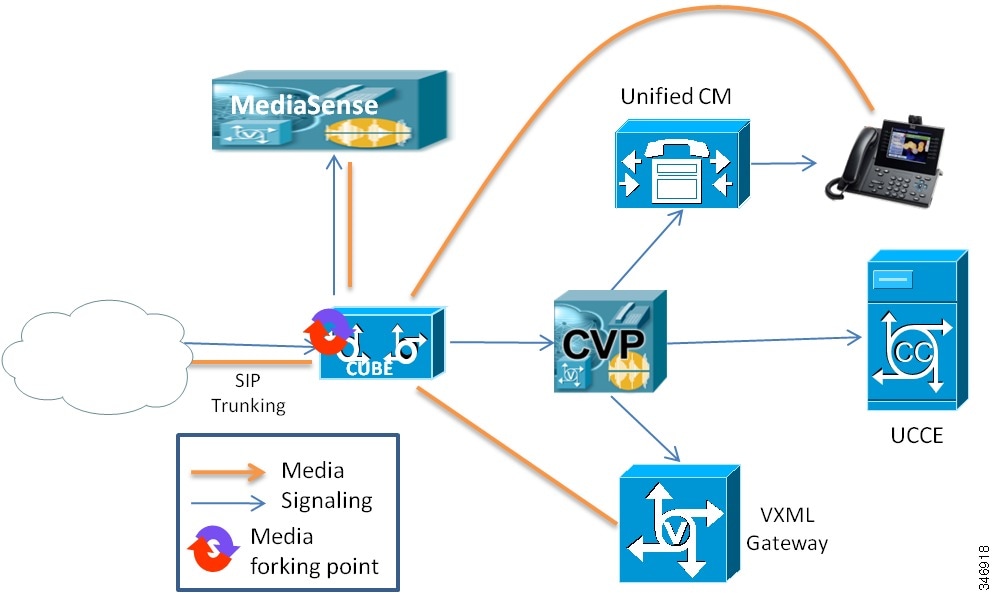
In this scenario, Unified CVP manages all call control operations including an initial delivery to a VXML gateway for music on hold or other treatment, a subsequent delivery to a Unified Contact Center Enterprise (Unified CCE) agent, and possible further network transfers to other agents and devices. All segments of the call are recorded.
When properly configured, Unified CVP affects these transfers by issuing SIP invitations to the destination device rather than to CUBE. This effectively re-routes the media without triggering a new dial peer match in CUBE.
As with most scenarios, media forking is configured on the outside dial peer.
CUBE deployments with Unified CVP - SIP trunks, with survivability

This scenario is identical to the preceding one except that the customer has elected to use the Unified CVP Survivability script to manage call failures and time of day routing. To use the Unified CVP Survivability script, place it on the outside dial peer in CUBE. IOS does not allow a script and media forking to occur on the same dial peer, however, so use the inside dial peer for media forking (as shown in the diagram). Configuring recording on the inside dial peer is risky because of the possibility that call manipulation may inadvertently trigger IOS to start a new dial peer matching operation. This would terminate the current recording session.
When properly configured, Unified CVP affects these transfers by issuing SIP invitations to the destination device rather than to CUBE. This prevents CUBE from triggering a new dial peer match.
Note
If Survivability kicks in to handle a mid-call failure of any kind, any audio played by that script (such as a "technical difficulties" message) cannot be recorded by MediaSense. But if the script transfers the call to a local phone, that conversation can be recorded if the local phone's dial peer is configured for media forking.
For information about REFER transfers, see the section "Additional deployment options and considerations".
CUBE deployments with Unified CVP - TDM trunks

A TDM MediaSense CUBE deployment for CVP is just like a SIP trunk deployment, except that a logically separate TDM gateway is placed ahead of the CUBE. CUBE still does the media forking on the outside dial peer and CUBE still acts as the router that Unified CVP interacts with.
If Survivability is used, it is placed on the POTS dial peer in the TDM gateway; not in the CUBE. This keeps the media forking on the outside dial peer in CUBE.
If Unified CVP is issuing DTMF tones to the PSTN (as in "*8 Transfer Connect" transfers), configure either "dtmf-relay sip-kpml" or "dtmf-relay sip-notify" on both ends of the call connection between the TDM gateway and the CUBE.
CUBE deployments with Unified CVP - outbound dialer
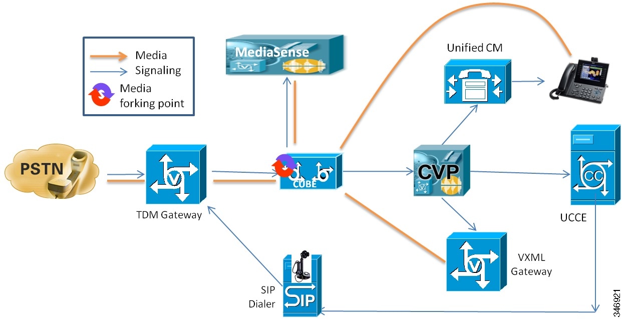
Outbound campaigns using the Unified CCE SIP outbound dialer are configured to directly instruct the TDM gateway to call the target phone number. Once a party answers and the answering machine detection algorithm determines that the answering party is a real person, the dialer instructs the TDM gateway to connect the call using CUBE to Unified CVP. From the perspective of CUBE and MediaSense, this appears the same as any another inbound call.
The outbound dialer is connected to the TDM gateway; not to the CUBE.
Additional deployment options and considerations
Redundant media forking using CUBE
Normally, one would apply the recording profile to the outside dial peer - the one which represents the side of the call which is external to the enterprise. It is also possible to configure media forking on both dial peers in a given call. This results in two independent recording sessions. The dial peers must be configured to deliver recordings to two separate and independent MediaSense clusters, implementing true recording redundancy. However, doing so severely impacts the performance of the CUBE. For sizing purposes, the CUBE call-carrying capacity should be assumed to be cut in half.
Percentage recording
Compliance recording, by definition, means that every call gets recorded. However some applications do not require that 100% of calls be recorded; in some cases spot-checking is sufficient.
Using CUBE, it is possible to record a pseudo-random sample of calls. This is accomplished by configuring multiple identical dial peers, assigning them equal preference values, but only configuring a subset of them for media forking. For example, one could record roughly one out of every three calls by configuring three identical inbound dial peers at preference level 5 and configuring media forking for only one of them.
Omitting the VRU segment from a recording
This applies to contact center recording where Unified CVP is used for call routing.
By forking media from CUBE, you can record the entirety of the caller's experience. This includes not only his or her conversation with one or more agents, but also any VRU or call queuing activity that may occur before the call is ever delivered to an agent. It can even be used to record the VRU activity if no agent is ever included in the call.
Some customers may want to omit the pre-agent VRU activity from the recording, particularly if it consists primarily of music on hold. One way to do this is by forking media from the agent's phone rather than from CUBE. But, if you need to fork media from CUBE for other reasons, you can accomplish this by causing Unified CVP to route the agent segment of the call back through the CUBE. You need to separate the ingress and media forking function from one another to do this, which means that you must either route the call through the ingress router a second time, or route it through a second router.
Both routing approaches require more hardware, but using a second router makes the configuration considerably easier. If your PSTN connection is TDM-based, you must route calls through the router a second time (or route them though a second router) anyway. Therefore, the remainder of this section assumes that the media forking router is separate from the ingress router, that the ingress router can be either a TDM gateway or an IP-only CUBE, and that the VXML function is running on the ingress router.
With a normal Unified CVP configuration, when an agent becomes available, Unified CVP sends a SIP invitation to the Unified Communications Manager that controls that agent's phone. Unified Communications Manager negotiates with the ingress router to connect the media stream from the router to the agent's phone. The ingress router itself never gets involved in routing that segment of the call because it never needs to figure out what IP address handles the selected agent's extension.
This arrangement is shown in the diagram below.
Unified CVP can also be configured so that the agent-segment invitation gets sent to the ingress router rather than to the Unified Communications Manager. The configuration can be done using Local Static Routes, an Outbound Proxy Server, or with Locally Resolved DNS SRV. One thing that will NOT work is checking the Enable Send Calls to Originator box in CVP's Dialed Number Pattern Configuration; that setting is only observed during the SendToVRU operation; not during the delivery to the agent. Once Unified CVP is so configured, you can define a dial peer in the ingress router that is specifically for routes to agent extensions—with Unified Communications Manager as the destination target.
This arrangement is shown in the following diagram.

To add media forking, insert a second router - a CUBE - to do the media forking, as shown in the following diagram.
The situation becomes more complex when you have multiple ingress sites, but the goal is still achievable using a combination of CVP's "Send Call to Originator" and "Significant Digits" capabilities to avoid hairpinning calls across the WAN . Send Call to Originator allows CVP to ensure that any given call's own ingress router is where its VXML activity is performed. Significant Digits can be used to ensure that when the call is delivered to an agent, it passes through a CUBE that is in the same site as the call's own ingress router. Significant Digits can also be used to localize VXML activity to any VXML-capable router at the ingress router's site, rather than being limited to the ingress router itself. The following diagram shows the final arrangement in a multi-ingress site scenario. In one site, we show two ingress gateways and one CUBE for media forking. The two ingress gateways are identical; both are performing both TDM-to-IP conversion and VXML functions. In the other site we show the same number of routers, but one router is used for TDM-to-IP conversion and a second router is dedicated to VXML activity.
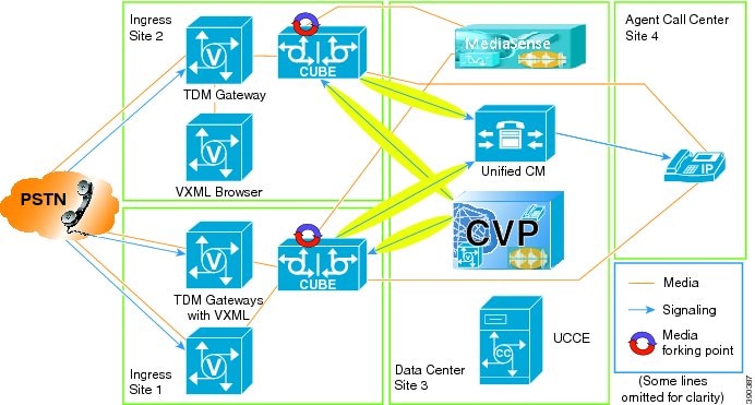
Regardless of the configuration, bandwidth usage must always be considered. In the design in the diagram immediately above, media flows twice over the WAN: once to and from the agent's phone, and a second time from the media forking CUBE to the MediaSense cluster. If you co-locate MediaSense with the CUBE, there is no problem. But if your deployment calls for centralizing MediaSense in a shared data center, then you must consider this extra bandwidth usage. In order to avoid the extra WAN traffic, you could also move the media forking CUBE to the data center where MediaSense is located. This can only work if your Unified Communications Manager cluster and your agent's phones are all in the same WAN location. Otherwise, you will end up causing more WAN traffic rather than less, since you cannot force calls to pass through a CUBE which is co-located with the selected agent's phone. Media streams will frequently hairpin first through a CUBE that is located where the agent is not. This technique also has the potential to confuse Unified Communication Manager's Call Admission Control (CAC) algorithm.
REFER transfers
By default, CUBE will pass a REFER transfer from Unified CVP on to the next upstream user agent. Once that transfer succeeds, CUBE is no longer in the signaling or media path and therefore cannot further record the call. If your deployment environment permits it, you can configure CUBE to "consume" the REFER transfer rather than pass it on. This results in CUBE itself executing the transfer, taking Unified CVP out of the loop, but keeping CUBE itself in the signaling and media path and recording the call. You can accomplish this by adding "voice service voip; no supplementary-service sip refer" to your CUBE configuration.
Note
If the inside dial peer is doing the media forking, then a REFER will always terminate the recording because it forces IOS to perform a new dial peer match operation.
Combining deployment models
The deployment models described in this document are not exclusive of each other. Any typical installation may have some inbound calls, some outbound calls, some that use Unified CVP, some that are not part of a contact center, some that use TDM trunks, some that use SIP trunks, some that fork media in CUBE, some that fork media at the phone, and so on. Generally speaking, the models here should be seen as describing the path that any one particular call may follow, while other calls may follow the paths which are covered in other deployment models. In that sense, all of these models may be combined indiscriminately, as long as any single call remains within one single model.
Combining TDM to IP conversion with media forking
By definition, only a SIP to SIP call may fork media in a CUBE. However, there is no reason that one cannot insert T1/E1 cards into an ISRG2 running CUBE software. Calls that arrive on a TDM port can be recorded if they are routed through the device twice: once as a TDM to SIP call, and once as an SIP to SIP call. This can be accomplished by configuring the device's outbound dial peer of the TDM to SIP call to specify itself in its session target parameter. Using some digit manipulation or other means of qualifying the call, the second time the call arrives it matches a different (VOIP) dial peer and looks like a SIP to SIP call. On this second pass through the router, media forking can be enabled.
In this flow, the call gets handled by the router twice, and therefore counts as two calls from a capacity perspective. Put the other way around, calls which follow this flow will effectively halve the stated capacity of the router, thus requiring twice as much router capacity for the same number of calls. If you intended to use the full capacity of the router for calls, you need two routers. This presents a choice: when you double the number of routers, you can either have all routers do both jobs (TDM and forking), or have half the routers do each job. Either approach may be used if engineered correctly.
For more information about ISR configuration, see https://supportforums.cisco.com/docs/DOC-23115.
Combining VXML with CUBE media forking
In Unified CVP deployments without MediaSense, it is possible to run VXML voice browser functions on the same router as CUBE, but Cisco does not support sharing media forking and VXML activities on the same router. VXML, especially with automatic speech recognition, uses a lot of the router's resources. It also makes for a complicated sizing exercise, since for media forking you must consider the total number of concurrent calls being handled, whereas for VXML you only consider the number of concurrent calls that are expected to be in queue or in IVR scripts.
In multi-site ingress deployments, especially branch office deployments, this means that CVP must be configured to use "SigDigits" functionality rather than "SendToOriginator", in order to prevent calls that are in queue from inadvertently traversing a WAN link.
See the CVP documentation for more information about these techniques.
When to use CUBE and when to use a built-in bridge (BiB)
For call recording to work from a solution perspective, it is not enough for MediaSense to be able to capture the forked media. Third party applications must also be able to find those recordings by correlating identifiers that they know about with the identifiers that MediaSense knows about.
Calls recorded using a built-in bridge (BiB) are usually no problem, since the third party application usually has a JTAPI interface it can use to find the xRefCi values. But calls recorded using CUBE only receive the Cisco-GUID (which it exposes as "CCID" - Call Correlation ID), but JTAPI does not expose the Cisco-GUID at all. In Unified CCE environments using CVP, the third party application can only get the Cisco-GUID for inbound calls using the CTIOS event stream.
For large scale deployments:
For smaller scale deployments, particularly those where the customer will be using the built-in Cisco MediaSense Search & Play portal to locate and playback recordings:
Exceptions and considerations:
- Unified CCE has a component (the SIP Dialer) for making automated outbound calls. Those calls end up looking like normal inbound calls as far as CUBE and MediaSense are concerned, so SIP Dialer calls can be treated as if they are normal Unified CCE inbound calls.
- Some partners or customers may be willing to use a less deterministic match than an explicit call identifier (such as the agent extension and the time frame). In these cases, the customer could use CUBE in all of the cases above—where BiB would otherwise be supported. (This is the basis for the relaxed recommendations for smaller scale deployments.)
- For internal (consult) calls or any calls between two Unified Communications Manager phones, BiB is preferred even if the customer is willing to use a less deterministic match than an explicit call identifier. It is possible to force these calls to hairpin through a CUBE, but the Unified Communications Manager configuration required to support this introduces restrictions on other Unified Communications Manager functions. Therefore, this type of configuration is not supported by Cisco.
- Unified CCE Mobile Agents raise additional considerations. BiB recording is not possible with these agents, but for inbound Unified CCE calls, they can be recorded with CUBE as described above. Consult calls to other agents can be recorded with BiB only if the other agent has a BiB-capable device (for example, he or she cannot be another Mobile Agent). Consult calls from one Mobile Agent to another Mobile Agent can only be recorded by forcing the call to hairpin through a CUBE. Directly dialed outbound calls from Mobile Agents can only be recorded using CUBE and can only be correlated using a non-deterministic approach (agent extension or dialed number, plus time frame).
Configuration requirements for other solution components
This section lists any configuration requirements that may affect how a particular deployment is designed or how components are ordered. For detailed configuration instructions, see the Cisco MediaSense User Guide.Unified Communications Manager
Unified Communications Manager must be configured appropriately to direct recordings to the MediaSense recording servers. To do this, you must configure a recording profile as well as various SIP parameters. Phone zones must be configured to avoid the use of iLBC or iSAC codecs and the Unified Communications Manager AXL service must be enabled on at least one of its servers (because MediaSense uses AXL to authenticate users.
Note
SIP over UDP is not supported for MediaSense.
CUBE
Cisco Unified Border Element (CUBE) software with media forking runs only on Cisco ISRG2 routers. Different models have different scalability specifications, but it is always advisable to provision these routers with the maximum amount of memory available. The 3945E in particular requires a minimum of 2GB memory. Media forking is not supported on ASR routers.
Every MediaSense CUBE deployment requires an AXL connection to a Unified Communications Manager for authentication purposes, even if it will not be processing calls. The connection can be to a Unified Communications Manager that is already installed and in use for other purposes, or it can be one that is installed specifically for use with MediaSense. The administrator configures one or more Unified Communications Manager end users and imports them into MediaSense as MediaSense API users.
Streaming media players
Examples of off-the-shelf media players include:
Each of these media players has its own advantages and disadvantages. VLC, for example, can only play one media track at a time. Quicktime is sometimes not able to handle the necessary authenticated RTSP redirect. Also, be aware that none of these media players are designed to handle silence. Playback of recordings that include silent segments may produce unpredictable behavior.
None of these players support AAC-LD, g.729 or g.722 codecs. A custom media player is required in order to play media that was recorded using those codecs. The built-in MediaSense media player, accessible through the Search and Play application, can play all of these audio codecs except AAC-LD.
Cisco does not produce, recommend, or support the use of these or any other third party media player. The only media player that Cisco supports is the one that is built in and provided by MediaSense.
SIP proxy servers
SIP proxy servers are currently not supported between MediaSense and Unified Communications Manager or CUBE.
Cisco Unified Session Manager Edition
In Cisco Unified Session Manager Edition (CUSME) deployments, MediaSense may only be placed at the "leaf" Unified Communications Manager cluster level. It is not currently supported at the centralized CUSME level. This means that each leaf cluster requires its own MediaSense cluster.
Contact Center Environments
- MediaSense does not explicitly interact with or support Unified Contact Center Enterprise (Unified CCE) or Unified Contact Center Express (Unified CCX). The recording functions that are available with the Agent and Supervisor Desktop clients on these products use different mechanisms for initiating and capturing recordings and require their own established recording solutions.
- For the Whisper Announcement feature, MediaSense does not record the whisper call between agent and supervisor (because the agent phone build-in-bridge normally doesn't include the supervisor-to-agent whisper in the forked media stream that it delivers to the recorder). On the other hand, if the supervisor phone is configured for forking, the whisper announcement is included in the supervisor phone recording.
- Equipment which monitors agent conversations by listening to a span port output and filtering on the agent phone MAC or IP address may not function properly when the phone is forking media for recording. This is because every RTP packet is emitted from the phone twice, and the listening device may not exclude those packets that are destined for the recording server from its capture. This results is the listener hearing an echo and needs to be taken into account for silent monitoring if the application calls for monitoring of conversations that are also being recorded.