
-
Cisco MediaSense Solution Reference Network Design Guide, Release 10.0(1)
-
Product overview
-
Characteristics and features
-
Codecs supported
-
Metadata database and the MediaSense API
-
Disk space management
-
System resiliency and overload throttling
-
MediaSense-specific deployment models
-
Solution environment
-
High availability
-
Security
-
Reporting and call correlation
-
Serviceability and administration
-
Design guidance
-
Compatibility matrix
-
Scalability and sizing
-
Index
-
 Feedback
Contents
- MediaSense-specific deployment models
- Server models supported
- Server types
- Grow your system
- Very large deployments
- Calls forked by Unified CM phones
- Calls forked by CUBE
- Virtual machine configuration
- Media storage alternatives
- Deploy multiple MediaSense virtual machines per server
- Geographical specifications
MediaSense-specific deployment models
This sections discusses the various options for deploying MediaSense servers and virtual machines.
- Server models supported
- Grow your system
- Very large deployments
- Virtual machine configuration
- Geographical specifications
Server models supported
MediaSense can only be deployed on a VMware hypervisor, which must be running on a
- Cisco B-series or C-series server with fiber channel-attached SAN storage (for at least the first two disks) or with directly attached hard disk drives
- or on a UCS-E module running within a Cisco ISR-G2 router
- or on selected Hewlett Packard (HP) or IBM servers (see Compatibility matrix below for versions and model numbers).
When ordering C-series servers, be sure to include either the battery backup or Super Cap RAID controller option. If one of these is not present or not operational, the write cache is disabled on these controllers. When the write cache is disabled, write throughput is significantly reduced. (See Compatibility matrix below for detailed disk requirements.)
The primary and secondary servers must be based on identical hardware, or at least have identical specifications in terms of CPU speed and disk I/O throughput. They must also be using the same version of VMware ESXi. Any asymmetry causes accumulating database latency in one server or the other. Expansion servers do not need to be running on the identical hardware.
Server types
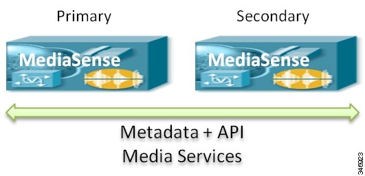
MediaSense is deployed on up to five rack-mounted servers or up to two UCS-E modules, depending on the capacity and degree of redundancy required. (in this context, "server" refers to a virtual machine, not necessarily a physical machine). There are three types of servers:
- Primary (required): Supports all database operations as well as media operations.
- Secondary (optional): Supports all database operations as well as media operations. Provides high-availability for the database.
- Expansion (optional): Provides additional capacity for media operations, but not for database operations. Expansion servers are only used in 7-vCPU deployments, and are never used in UCS-E module deployments.
The following diagram depicts a primary-only deployment model:

Customers who require database redundancy can deploy a secondary server, as shown below:
If additional recording capacity is required, expansion servers are deployed, as shown below:
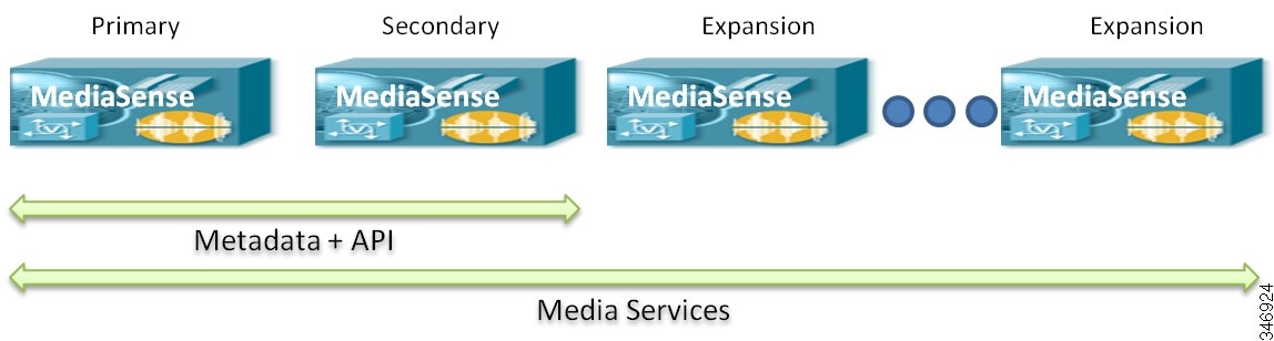
Note
Expansion servers are not supported in deployments which do not use the full 7-vCPU template.
All servers (including UCS-E servers) run the same installed software; they differ only in function and capacity. The primary server is always the first server to be installed and is identified as such during the installation process. Secondary and expansion servers are identified during the initial web-based setup process for those nodes (after installation is complete).
Recordings are always stored on the disks which are attached to the server which initially captured the media.
UCS-E-based two-server clusters may be deployed with both blades in the same ISRG2 router or with one blade in each of two ISRG2 routers. The latter is typically preferred from a fault isolation perspective but is not required. A MediaSense cluster must be UCS-E-based or rack-mount server based. It cannot be made up of a combination of the two.
Grow your system
There are two reasons for expanding system capacity: to be able to handle more simultaneous calls, and to increase the retention period of your recordings.
If your goal is to handle more calls, then you can simply add nodes to your cluster. Each nodes adds both simultaneous activity capacity – the ability to perform more parallel recording, monitoring, download and playback activities – and storage capacity. Servers may be added to a cluster at any time, but there is no ability to remove servers from a cluster.
Once your cluster has reached its maximum size (5 nodes for 7 vCPU systems, 2 nodes for everything else), your only option is to add a new cluster. If you do, you must arrange your clusters with approximately equal numbers of nodes. If that is not possible, then you should at least arrange the call distribution such that an approximately equal number of calls is directed to each cluster, possibly leaving the larger cluster underutilized. For more information, see Very Large Deployments.
There is no capability to remove a node from a cluster once it has been added.
If your intention is to achieve a longer retention period for your recordings, there are two options. You can add nodes, as described above, or you can provision more storage space per node. Each node can handle up to 12 TB of recording storage, as long as the underlying hardware can support it. UCS-B/C servers with SAN can do so easily, but servers using direct attached storage (DAS) and low-end UCS-E servers are more limited.
As with nodes in a cluster, there is no capability to remove storage capacity from a node once it has been installed.
Very large deployments
Customers who require capacity that exceeds that of a single MediaSense cluster must deploy multiple independent MediaSense clusters. In such deployments, there is absolutely no interaction across clusters; no cluster is aware of the others. Load balancing of incoming calls does not extend across clusters. One cluster might reach capacity and block subsequent recording requests, even if another cluster has plenty of remaining room.
API clients need to be designed such that they can access all of the deployed clusters independently. They can issue queries and subscribe to events from multiple clusters simultaneously, and even specify that multiple clusters should send their events to the same SWS URL. This permits a single server application to receive all events from multiple clusters. Some MediaSense partner applications already have this capability. MediaSense's built-in Search and Play application, however, does not.
The following list is a summary of whether multiple call controllers can share one MediaSense cluster and whether one call controller can share multiple MediaSense clusters.
Calls forked by Unified CM phones
For Unified Communications Manager phone recording, phones must be partitioned among MediaSense clusters such that any given phone will be recorded by one specific MediaSense cluster only; its recordings will never be captured by a server in another cluster. (But there is an option for full cluster failover, such as in case of a site failure. See High Availability.)
In some deployments there is a need for multiple Unified CM clusters, possibly tied together in an SME network, to share one or a small number of MediaSense clusters. In this arrangement, there is a chance that two calls from different Unified CM clusters will carry the same pair of xRefCi values when they reach MediaSense. This would cause those two calls to be incorrectly recorded or not recorded at all. (The statistical probability of this sort of collision is incredibly small and need not be considered.) This arrangement, therefore, is fully supported.
If your application uses the startRecord API function that asks MediaSense to make an outbound call to a specified phone number and begin recording it, only a single Unified Communications Manager node may be configured as the call controller for this type of outbound call.Calls forked by CUBE
For CUBE recording, the situation is more flexible. One or more CUBE systems may direct their forked media to one or more MediaSense clusters. There is no chance of a call identifier collision because MediaSense uses CUBE's Cisco-GUID for this purpose, and that GUID is globally unique.
Since MediaSense clusters do not share the load with each other, CUBE must distribute the load with its recording invitations. This can be accomplished within each CUBE by configuring multiple recording dial peers to different clusters so that each one is selected at random for each new call. Alternatively, each CUBE can be configured with a preference for one particular MediaSense cluster, and other mechanisms (such as PSTN percentage allocation) can be used to distribute the calls among different CUBE devices.
If your goal is to provide failover among MediaSense clusters rather than load balancing, see High Availability.
Virtual machine configuration
Cisco provides an OVA virtual machine template in which the minimum size storage partitions and the required CPU and memory reservations are built in. VMWare ESXi enforces these minimums and ensures that other VMs do not compete with MediaSense for these resources. However, ESXi does not enforce disk throughput minimums. Therefore, you must still ensure that your disks are engineered such that they can provide the specified IOPS and bandwidth to each MediaSense VM.
The Cisco-provided OVA template contains a dropdown list that allows you to select one of the supported VMware virtual machine template options in each release for MediaSense servers. These template options specify (among other things) the memory, CPU, and disk footprints for a virtual machine. For each virtual machine you install, you must select the appropriate template option on which to begin your installation. You are required to you use the Cisco-provided templates in any production deployment. For low volume lab use, it is possible to deploy on lesser virtual equipment, but the system will heavily constrain its own capacity and display warning banners that you are running on unsupported hardware.
The following table summarizes the template options provided.
Template option vCPUs Memory Disk CPU reservation Maximum total recording space supported Notes Primary or secondary node
2
6 GB
80 GB for OS
80 GB for DB
210 GB for media
2200 MHz
420 GB across two nodes.
No expansion nodes supported.
Users can add additional media disks.
2,4
Primary or secondary node
4
8 GB
80 GB for OS
600 GB for DB
210 GB for media
3200 MHz
24 TB across two nodes.
No expansion nodes supported.
Minimum 210 GB per node provisioned by default
Users can add additional media disks.
UCCX integration should use this template
2,3,4
Expansion node
7
16 GB
80 GB for OS
80 GB for DB
10000 MHz
12 Terabytes per expansion node.
Minimum 210 GB per node provisioned by default.
Users can add additional media disks.
1,2,3
Primary/secondary node
7
16 GB
80 GB for OS
600 GB for DB
210 GB for media
15000 MHz
12 Terabytes per primary or secondary node.
Minimum 210 GB per node provisioned by default.
Users can add additional media disks.
2,3
Notes:
- All rack-mount expansion servers must use the expansion template option.
- All disks must be "thick" provisioned. Thin provisioning is not supported.
- The primary, secondary and expansion OVA template options provision the minimum 210 GB by default. Additional space may be added before or after MediaSense software installation. Once provisioned, recording space may never be reduced. The total amount of media storage across all nodes may not exceed 60 Terabytes on 5-node clusters or 24 Terabytes on 2-node clusters.
- The primary and secondary node 2 vCPU and 4 vCPU templates are suitable for UCS-E blade deployments, although they can also be used on larger systems. Most supported UCS-E blades have more physical disk space available than the VM template allocates; the unused space may be used for recorded media or uploaded media.
Media storage alternatives
On rack-mount servers, two storage alternatives for recorded data are currently supported:
Note
Network Attached Storage (NAS) is not supported in any MediaSense configuration and SAN storage is not supported on UCS-E configurations.
Depending on the hardware model and options purchased, any single node can offer up to 12TB of storage—a maximum of 60TB of storage across five servers. It is not necessary for all servers to be configured with the same number or type of virtual disks. (See the Compatibility matrix section for detailed specifications and other storage configuration requirements.)
RAID configurations
This section is applicable to UCS C-series servers only.
MediaSense must be configured with RAID-10 for the database and OS disks and either RAID-10 or RAID-5 for media storage. Using RAID-5 results in hardware savings. It is slower, but fast enough for media storage. All of the TRC configurations for UCS C-series servers include an internal SD card which is large enough to house the ESXi hypervisor. Therefore, Cisco supports installation of ESXi on the SD card and having the MediaSense application installed on the remaining disk drives.
That RAID-10 group would have to hold the ESXi hypervisor as well as the MediaSense application, which is not generally a recommended practice. Fortunately, all the TRC configurations for UCS C-series servers include an internal SD card which is large enough to house ESXi. Cisco therefore recommends that ESXi be installed on the SD card and the MediaSense application be installed on the remaining disk drives.
Deploy multiple MediaSense virtual machines per server
As of Release 9.0(1), MediaSense is no longer required to be the only virtual machine running on a physical server. Other applications can share the server, as long as MediaSense is able to reserve the minimum resources it requires.
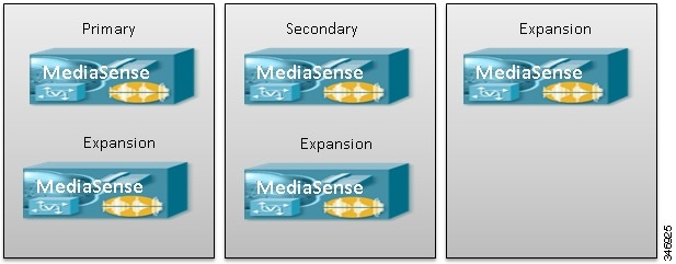
You can also deploy multiple MediaSense VMs on a single host. When doing so however, ensure that the primary and secondary nodes do not reside on the same physical host. For example, if your servers can support two MediaSense VMs, then you might lay out a 5-node cluster in this way:
If your servers can support three MediaSense VMs, then you might lay them out as follows:
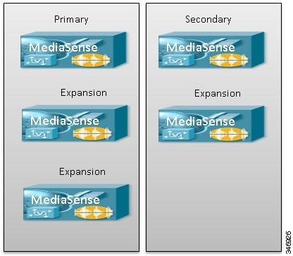
You can determine how many MediaSense VMs a particular server model will support by referring to the UC Virtualization Wiki and use the number of physical CPU cores as a guide. Models with 8 or more physical cores can support 1 MediaSense VM; models with 14 or more physical cores can support 2 MediaSense VMs, and models with 20 or more physical cores can support 3 MediaSense VMs.
Geographical specifications
All MediaSense servers within a cluster must be in a single campus network. A campus network is defined as a network in which the maximum round-trip delay between any pair of MediaSense servers is less than 2 milliseconds. (Some Metropolitan Area Networks (MANs) may fit this definition as well.)
Other solution components, however, may connect to the MediaSense cluster over a WAN, with certain caveats:
- In Unified Communications Manager deployments, media forking phones may be connected to MediaSense over a WAN.
- SIP Trunks from Unified Communications Manager may also be routed over a WAN to MediaSense, but calls may evidence additional clipping at the beginning of recordings due to the increased round trip delay.
- The connection between CUBE and MediaSense may be routed over a WAN with the same warning—affected calls may evidence additional clipping at the beginning of recordings due to the increased round trip delay.
- The AXL connection between Unified Communications Manager and MediaSense may be routed over a WAN, but API and administrator sign-in times may be delayed.
- From a high availability standpoint, API sign-in has a dependency on the AXL link. If that link traverses a WAN which is unstable, clients may have trouble signing in to the API service or performing media output requests such as live monitoring, playback, and recording session download. This applies to remote branch deployments as well as centralized deployments, and to CUBE deployments as well as Unified CM deployments.
