Call Recording and Monitoring
Revised: January 15, 2015; OL-30952-03
Call monitoring and recording solutions provide a way to monitor and record audio and video calls that traverse various components in a Unified Communications and Collaboration solution, such as Cisco IP Phones, Cisco Unified Border Element devices, or Cisco switches. These recordings can then be used by call centers and other enterprise for various purposes such as compliance purposes, transcription and speech analysis, or for podcasting and blogging purposes. This chapter provides an overview of various call recording solutions available for Cisco Unified Communications and Collaboration solutions for both audio and video calls. The chapter also outlines basic design considerations for call recording solutions embedded within a Cisco Unified Communications and Collaboration solution.
What’s New in This Chapter
Table 25-1 lists the topics that are new in this chapter or that have changed significantly from previous releases of this document.
|
|
|
|
|---|---|---|
Types of Monitoring and Recording Solutions
This section describes the following types of call recording and monitoring solutions:
- SPAN-Based Solutions
- Unified CM Call Monitoring and Recording
- Cisco MediaSense
- Agent Desktop
- Cisco TelePresence Content Server
SPAN-Based Solutions
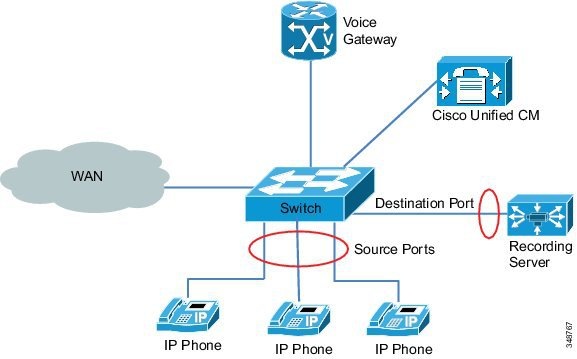
Recording solutions based on a Switched Port Analyzer (SPAN) use the packet sniffing technology for recording calls. SPAN is a method of monitoring network traffic. When SPAN is enabled on a switch port or VLAN, the switch sends a copy of all network packets traversing that port or VLAN to another port where a recording or monitoring server (such as Cisco Unified Contact Center Express, Cisco Unified Workforce Optimization Quality Management, or a third-party recording server, for example) analyses those packets. It detects and decodes the VoIP packets embedded in the network traffic and stores them as audio on a storage device. SPAN can be enabled on the ports connected to a Cisco Voice Gateway or Cisco IP Phones, as required. For example, for recording internal calls between IP phones, SPAN should be enabled on switch ports connected to the IP phones.
Figure 25-1 illustrates a SPAN-based recording solution deployment for recording internal calls. The ports marked as source ports connected to IP phones are mirrored to the destination port connected to the recording server.
Figure 25-1 SPAN-Based Recording Call Flow for Internal Calls
Several Cisco partners provide SPAN-based recording servers and applications for Cisco Unified Communications and Collaboration solutions. For technical details, refer to the specific partner product information in the Cisco Developer Network Marketplace Solutions Catalog, available at
https://marketplace.cisco.com/catalog/search?utf8=%E2%9C%93&x=48&y=6&search%5Btechnology_category_ids%5D=1900
In addition, network traffic flow needs to be considered for appropriate bandwidth provisioning when port mirroring is enabled.
SPAN-Based Recording and Virtualization
This section reviews some common SPAN-based deployments with virtualization enabled and lists some of the limitations. VMware provides support for the SPAN feature on VMware vSphere Distributed Switch (VDS) starting with vSphere 5.0.
In a virtualized setup, some of the Unified Communications and contact center applications and the port analyzer application may be deployed on virtual machines on the same host or on different hosts. There are some limitations to SPAN-based recording solutions in a virtualized setup. For example, the following features are not supported for deployments of Cisco Unified Contact Center Enterprise (Unified CCE) with virtualization:
- Remote silent monitoring
- SPAN-based silent monitoring and recording on Cisco Unified Computing System (UCS) B-Series chassis

Note![]() SPAN-based silent monitoring and recording is not supported on the UCS B-Series chassis.
SPAN-based silent monitoring and recording is not supported on the UCS B-Series chassis.
Unified CM Call Monitoring and Recording
Cisco Unified CM call monitoring and recording solutions provide the ability to monitor and record customer conversations for compliance purpose. The Silent Call Monitoring feature allows a supervisor to listen to a conversation between an agent and a customer with neither the agent nor the customer aware of the supervisor's presence on the call. The Call Recording feature allows system administrators or authorized personnel to archive conversations between the agent and the customer.
Cisco Unified CM supports automatic and selective recordings. In automatic recording, Unified CM automatically records every call that is connected on the endpoint. In selective recording, the user has to explicitly request Unified CM to start the recording for the call on the endpoint. Users can make the recording request by pressing the Start Recording button on the endpoint or by sending the recording request from the JTAPI or TAPI application. To start the recording, Unified CM sends the request to the forking device to fork the media of the conversation to the recording server, where the media captured and archived. Unified CM utilizes the following Cisco Collaboration technologies to perform call monitoring and recording:
Cisco Unified IP Phones-Based Call Monitoring and Recording
Cisco Unified CM uses an architecture based on the IP phones to provide call monitoring and recording for audio calls. It uses the IP phone built-in bridge (BIB) to enable call monitoring and recording.
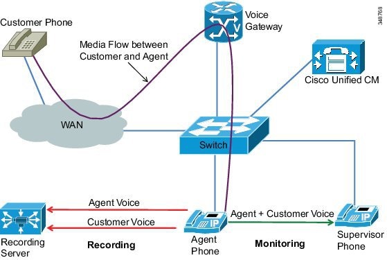
For call monitoring, the agent phone combines the two voice RTP streams (one for the agent and one for the customer) on the agent phone and sends the resulting stream to the supervisor phone. In addition, whisper coaching allows the supervisor to talk to the agent during the call monitoring session. Call monitoring and whisper coaching can be invoked by call center applications through the JTAPI or TAPI interfaces of Unified CM.
For recording, the agent phone forks the two streams to the recording server. The two streams, one for the agent voice and one for the customer voice, get recorded separately. If a single stream is desired, customers can use third-party applications to mix the recorded streams to produce the conversation.
Figure 25-2 illustrates the basic setup for Unified CM call monitoring and recording with IP phones. Agent and supervisor phones are CTI controlled. With this type of call monitoring and recording, the agent phone cannot be decoupled from the media forking device and, therefore, the solution can be deployed only within a single cluster.
Figure 25-2 Unified CM Call Monitoring and Recording with IP Phones
For a list of Cisco Unified IP Phones that support call monitoring and recording with Unified CM, refer to the Unified CM Silent Monitoring and Recording Supported Device Matrix, available at
http://developer.cisco.com/web/sip/wikidocs/-/wiki/Main/Unified+CM+Silent+Monitoring+Recording+Supported+Device+Matrix
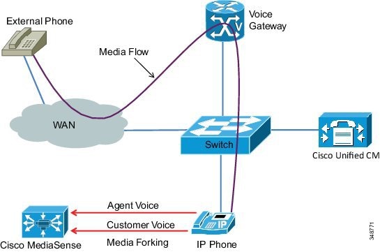
Cisco Unified CM Network-Based Recording
Cisco Unified CM utilizes the voice gateway media forking capability for call recording. When an external call is connected with an end user on the phone, Unified CM requests the gateway to fork the media of the conversations to the recording server (such as Cisco MediaSense) through the UC Gateway Services API. The forked media consists of two RTP streams, one for end user voice and one for caller voice, and the recording server captures the streams separately. Because the gateway is on the media and signaling path of the call, customer can use this solution to perform recording for all calls connected through the gateway. This includes external calls connected with end users on Cisco Unified IP Phones, Cisco Softphone (Cisco Jabber, for example) running on a PC, or mobile phones in remote destinations. Essentially, once an external call terminates on the voice gateway that Unified CM is registered with, the entire conversation of the call from the caller's perspective can be recorded, no matter where the call goes inside the enterprise.
Cisco Unified CM network-based recording supports additional call types other than the ones described above. For details, refer to the latest version of the Cisco Unified Communications Manager Features and Services Guide, available at
http://www.cisco.com/en/US/products/sw/voicesw/ps556/prod_maintenance_guides_list.html
Note![]() Invoking media forking from a voice gateway produces two RTP streams, and if silent monitoring is required, the application is responsible for mixing the streams.
Invoking media forking from a voice gateway produces two RTP streams, and if silent monitoring is required, the application is responsible for mixing the streams.
Figure 25-3 illustrates the basic setup for Cisco Unified CM network-based recording. Cisco Unified CM and the voice gateway are connected through a recording-enabled SIP trunk. Unified CM registers with the UC Gateway Services API in the gateway through the HTTP interface. This enables Unified CM to receive call event notifications for all calls passing through the gateway and to decide when to start or stop the recording. Depending on the recording option configured, when a gateway call is connected with an end user on the phone, Unified CM might notify the gateway immediately to fork the media or wait for the user indication to start the recording before notifying the gateway. Unified CM notifies the gateway to stop forking the media upon user indication to stop the recording, or the gateway automatically stops the recording upon call termination. The requests to start or stop the recording are sent over the HTTP interface using the Extended Media Forking (XMF) API.
Figure 25-3 Basic Setup for Cisco Unified CM Network-Based Recording
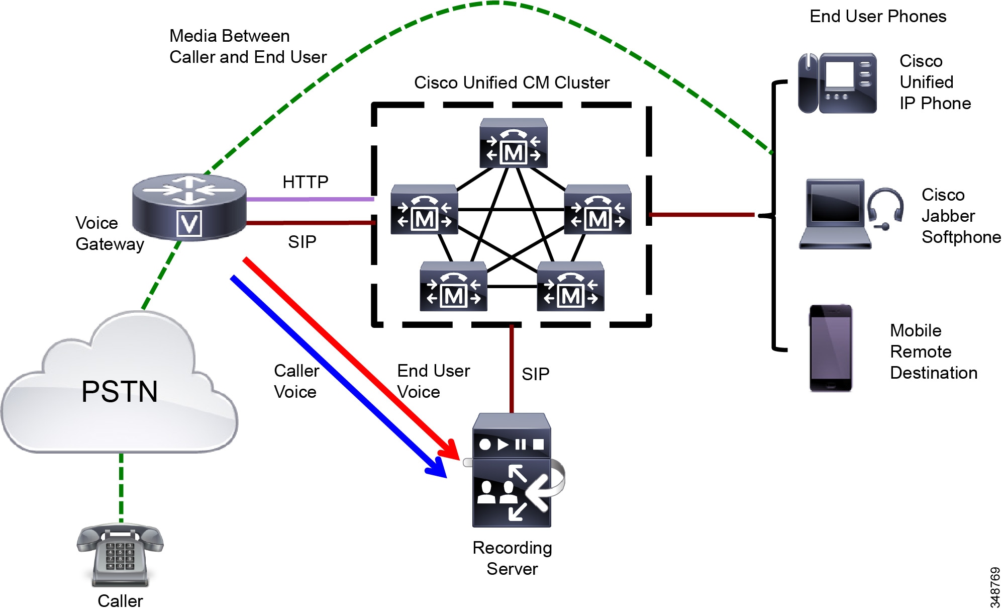
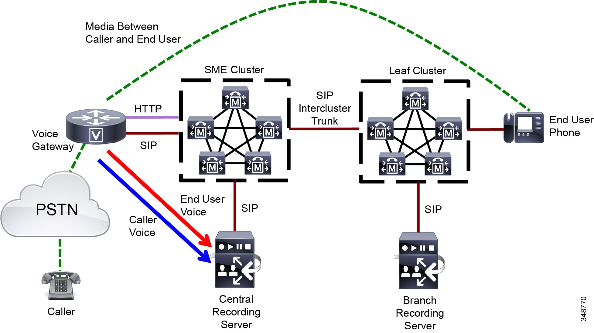
With Unified CM network-based recording, the end user phone and the media forking device (voice gateway) are decoupled. They can register to the same Unified CM cluster (as shown in Figure 25-3) or to separate Unified CM clusters. Therefore, this solution could be deployed in a multi-cluster environment such as Cisco Unified CM Session Management Edition (SME). Figure 25-4 illustrates an example of deploying Unified CM network-based recording with SME, where the voice gateway registers to the SME cluster and the end user phone registers to the leaf cluster. The SME cluster and leaf cluster are connected by a SIP intercluster trunk (ICT) with the gateway recording option enabled on both sides. Thus, the recording invocation requests and responses can be sent between SME and leaf clusters. Also, customers have the option to deploy the recording server centrally in the SME cluster with the voice gateway or to distribute the recording servers in all the leaf clusters.
Figure 25-4 Cisco Unified CM Network-Based Recording Deployment with SME
When deploying Unified CM network-based recording, observe the following guidelines:
- This solution is supported on a variety of platforms; for example, Cisco Unified Border Element running on a Cisco Integrated Services Router (ISR) G2. For detail requirements, refer to the latest version of the Cisco Unified Communications Manager Features and Services Guide, available at
http://www.cisco.com/en/US/products/sw/voicesw/ps556/prod_maintenance_guides_list.html
- Only SIP is supported between the voice gateway and Cisco Unified CM, but SIP proxy servers are not supported.
- For inter-cluster recording, only a SIP trunk is supported to interconnect the clusters.
- Secure recording is not supported.
- IPv6 is not supported.
Cisco Unified CM allows the system administrator to set the Recording Media Source preference (either Phone Preferred or Gateway Preferred) when enabling recording on the line appearance of the device. Based on the preference configured and the recording resource availability in the system, Unified CM makes the decision to use either the gateway or the phone as the recording media source. For example, if an IP phone has recording enabled with Phone Preferred but there is no recording resource available (the phone does not have a built-in bridge), the gateway would be used for call recording.
Regardless of the media forking devices used by Unified CM for call recording, Unified CM always provides the metadata about the near-end and far-end parties of the recorded calls to the recording server. The metadata resides in the FROM header of the SIP Invite and other SIP messages that are sent between Unified CM and the recording server.
For details about Unified CM silent call monitoring and call recording features, refer to the latest version of the Cisco Unified Communications Manager Features and Services Guide, available at
http://www.cisco.com/en/US/products/sw/voicesw/ps556/prod_maintenance_guides_list.html
Cisco MediaSense
Cisco MediaSense is a SIP-based, network-level service that provides voice and video media recording capabilities for network devices. It is fully integrated into the Unified CM architecture and can capture and store VoIP conversations that traverse appropriately configured Unified CM IP phones or Cisco Unified Border Element devices by invoking media forking capabilities on the IP phones and Cisco Unified Border Element devices. In addition, an IP phone user or SIP endpoint device may call the Cisco MediaSense system directly in order to leave a recording that consists of only media generated by that user. Such recordings may include video as well as audio, thus offering a simple and easy method for recording video blogs and podcasts. While the recording is in progress, it can also be streamed live using the built-in media player or a third-party media player such as VLC or Apple QuickTime. Cisco MediaSense uses an HTTP interface to access and play back recordings or perform live streaming.
Note![]() Most but not all Cisco Unified IP Phones support media forking. Those that do not support media forking cannot be used for phone-based recording. For a list of IP phones that support phone-based media recording with Cisco MediaSense, refer to the latest version of the Solution Reference Network Design for Cisco MediaSense, available at http://www.cisco.com/en/US/products/ps11389/products_implementation_design_guides_list.html.
Most but not all Cisco Unified IP Phones support media forking. Those that do not support media forking cannot be used for phone-based recording. For a list of IP phones that support phone-based media recording with Cisco MediaSense, refer to the latest version of the Solution Reference Network Design for Cisco MediaSense, available at http://www.cisco.com/en/US/products/ps11389/products_implementation_design_guides_list.html.
Cisco MediaSense also provides an administration and reporting interface to configure the cluster and manage recordings. It provides secure media storage on an encrypted storage area network (SAN). It does not currently support secure media relay using sRTP or other means.
Deployment of Cisco MediaSense
Cisco MediaSense runs on top of VMware on a Cisco supported virtualized platform such as Cisco Unified Computing System (UCS) B-Series or C-Series. It can be deployed as a single server or as a cluster of up to a five nodes, depending upon the required capacity of the system. It can also be deployed on a Cisco UCS E-Series (UCS-E) platform with up to two USC-E modules installed with the branch router. In a multi-node setup, there are three types of nodes:
- Primary — Provides both database and media operations.
- Secondary — Provides high availability for the database as well as both database and media operations.
- Expansion — Provides additional capacity for media operations but no data operations. It is not supported in Cisco UCS-E deployments.
When deploying multiple Cisco MediaSense clusters, Cisco recommends partitioning the IP phones carefully among the various clusters so that each IP phone gets recorded by only one cluster.
Note![]() SIP proxy servers are not supported between Cisco MediaSense and Unified CM or Cisco Unified Border Element.
SIP proxy servers are not supported between Cisco MediaSense and Unified CM or Cisco Unified Border Element.
Cisco MediaSense integrates with the following Cisco Collaboration technologies to capture the media:
Integration of MediaSense with Unified CM for Call Recording from Cisco Unified IP Phones
Figure 25-5 illustrates a basic Cisco MediaSense deployment for call recording with Unified CM and Cisco Unified IP Phones. Once a call is established from a signaling perspective, the media flows directly between the external phone and the internal IP phone. The IP phone is configured to fork media to Cisco MediaSense for call recording. If the call gets transferred to another IP phone, the current call recording session ends. If the phone that accepts the transferred call is configured for recording, a new call recording session will be started.
Figure 25-5 Integration of Cisco MediaSense and Unified CM Call Recording for IP Phones
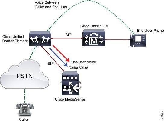
Integration of Cisco MediaSense with Cisco Unified CM Network-Based Recording
With this integration, Cisco MediaSense can be utilized to perform compliance or on-demand recording through Unified CM configuration. Under the control of Unified CM, call recording media can be sourced from either a Cisco Unified IP Phone or Cisco Unified Border Element that connects with Unified CM over a SIP trunk. Depending on the call flow and call participants, Unified CM dynamically selects the device to source the media to be captured. Unified CM network-based recording enables Unified CM to route recording calls, regardless of device, location, or geography. Figure 25-6 illustrates the basic deployment of Unified CM network-based recording with Cisco MediaSense. For more information about Unified CM network-based recording, refer to the section on Cisco Unified CM Network-Based Recording.
Note![]() Cisco MediaSense supports Unified CM network-based recording for IP-to-IP media forking using Cisco Unified Border Element, but TDM-to-IP media forking is not supported.
Cisco MediaSense supports Unified CM network-based recording for IP-to-IP media forking using Cisco Unified Border Element, but TDM-to-IP media forking is not supported.
Figure 25-6 Integration of Cisco MediaSense and Unified CM Network-Based Recording

Integration of Cisco MediaSense with Cisco Unified Border Element Media Forking
With this integration, Cisco MediaSense can be utilized to perform compliance recording. When a call going through Cisco Unified Border Element (CUBE) is connected, CUBE can be configured to fork the media to Cisco MediaSense and thus provides the ability to capture the end-to-end conversation from a caller's perspective, no matter how the call traverses through the enterprise. Figure 25-7 illustrates a basic Cisco MediaSense deployment using Cisco Unified Border Element media forking for call recording. In this configuration, Cisco MediaSense is directly integrated with Cisco Unified Border Element for media forking, and the media forking control messages are sent between the two components without involving Unified CM. The Cisco Unified Border Element device does media forking by means of a recorder profile configuration attached to one or more dial peers. Cisco recommends attaching the recording profile to the outbound dial peer.
Figure 25-7 Integration of Cisco MediaSense with Cisco Unified Border Element Media Forking for Call Recording
If the caller and end user are connected via the video-enabled endpoints in which the call traverses through Cisco Unified Border Element (CUBE), CUBE can be configured to fork both the audio and video of the caller and end user to Cisco MediaSense for recording. Figure 25-8 illustrates the Cisco MediaSense deployment using Cisco Unified Border Element media forking for recording in a video-enabled contact center. In this deployment, once the caller and agent are connected on the video call, CUBE forks the caller and agent's audio and video to Cisco MediaSense for capturing.
Figure 25-8 Integration of Cisco MediaSense with Cisco Unified Border Element Media Forking for Audio and Video Recording
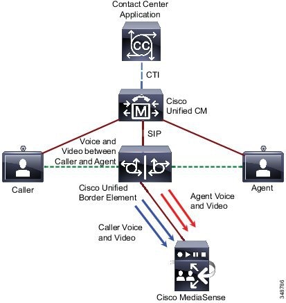
Note![]() Recording using Cisco Unified Border Element media forking is supported only for SIP-to-SIP call flows. Cisco Unified Border Element software with media forking runs only on Cisco Integrated Services Router (ISR) platforms. Media forking is not supported on Cisco Aggregation Services Routers (ASR).
Recording using Cisco Unified Border Element media forking is supported only for SIP-to-SIP call flows. Cisco Unified Border Element software with media forking runs only on Cisco Integrated Services Router (ISR) platforms. Media forking is not supported on Cisco Aggregation Services Routers (ASR).
Any requirements around call recording need to be considered when doing capacity planning for Cisco Unified Border Element devices because they require additional DSP resources and memory resources. For the memory requirements, Cisco recommends provisioning the Cisco Unified Border Element devices with the maximum amount of memory when enabling call recording. Also, media forking increases bandwidth usage on the link between the Cisco Unified Border Element and the Cisco MediaSense server. The percentage of calls getting recorded needs to be factored in when calculating bandwidth requirement.
For details on configuring Cisco Unified Border Element devices to enable network-based recording, refer to the section on Network-Based Recording Using Cisco UBE in the Cisco Unified Border Element Protocol-Independent Features and Setup Configuration Guide, available at
http://www.cisco.com/en/US/docs/ios-xml/ios/voice/cube_proto/configuration/15-mt/cube-proto-15-mt-book.html
Cisco SME Deployments
In a deployment of Cisco Unified CM Session Management Edition (SME), Cisco MediaSense is supported only in the leaf clusters. The phones that need to be recorded and the Cisco MediaSense cluster must be part of the same SME leaf cluster. Separate MediaSense clusters need to be deployed for different SME leaf clusters. Cisco MediaSense deployed in an SME leaf cluster can record calls only for that leaf cluster.
For more details on other supported deployments available with Cisco MediaSense, refer to the section on Solution-Level Deployment Models in the latest version of the Solution Reference Network Design for Cisco MediaSense, available at
http://www.cisco.com/en/US/products/ps11389/products_implementation_design_guides_list.html
Agent Desktop
Agent desktop monitoring and recording solutions are specific to contact center deployments that enable supervisors to do silent monitoring and initiate call recording when needed. Several agent desktop monitoring and recording solutions are available, such as:
- Cisco Agent Desktop (CAD) Silent Monitoring and Recording
- Cisco Remote Silent Monitoring (RSM)
- Cisco Finesse Agent Desktop integration with Cisco MediaSense
These solutions are described in details in the following documents:
http://www.cisco.com/en/US/products/sw/custcosw/ps1844/products_implementation_design_guides_list.html
http://www.cisco.com/en/US/products/sw/custcosw/ps1846/products_implementation_design_guides_list.html
Cisco TelePresence Content Server
The Cisco TelePresence Content Server is a network appliance that provides the ability to record and stream Cisco TelePresence and third-party video conferences and multimedia presentations that can be distributed to media devices or shared through applications such as Cisco Show and Share.
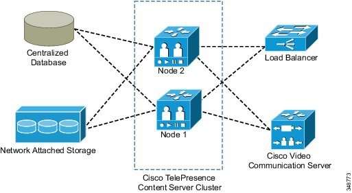
The Cisco TelePresence Content Server can be used to record content and create media from any H.323 or SIP videoconference endpoint. Cisco TelePresence Content Server release 5.3 supports up to 10 recording ports. The TelePresence Content Server solution can be deployed as a single Content Server or as a cluster with up to 10 servers in a Cisco TelePresence Video Communication Server (VCS) cluster. Clustering several servers together increases the total recording and playback capacity. A cluster can have a mix of 5-port and 10-port servers. The cluster uses a network load balancing (NLB) solution that distributes incoming user HTTP requests across the cluster. Each Cisco TelePresence Content Server cluster is registered to a Cisco VCS cluster that load-balances the inbound calls. Note that all servers in a cluster must be located at the same physical site, within a network round-trip time (RTT) to the Network Attached Storage (NAS) and Structured Query Language (SQL) servers not exceeding 10 ms. Figure 25-9 illustrates TelePresence Content Server clustering.
Note![]() The Cisco TelePresence Content Server clustering option supports H.323 protocol only. SIP registration and SIP calling are not supported. For additional clustering requirement details, refer to the latest version of the Cisco TelePresence Content Server Administration and User Guide, available at
The Cisco TelePresence Content Server clustering option supports H.323 protocol only. SIP registration and SIP calling are not supported. For additional clustering requirement details, refer to the latest version of the Cisco TelePresence Content Server Administration and User Guide, available at
http://www.cisco.com/en/US/products/ps11347/prod_maintenance_guides_list.html.
Figure 25-9 Cisco TelePresence Content Server Clustering
Cisco TelePresence Content Server Deployments
The Cisco TelePresence Content Server is not supported with Unified CM-only deployments. The following deployments are supported for the Cisco TelePresence Content Server recording solution:
Cisco recommends deploying the TelePresence Content Server solution with Cisco VCS to enable all features.
This deployment does not support all the features (for example, SIP functionality) that are available in a TelePresence Content Server deployment with Cisco VCS.
This is the most simplistic deployment but is not recommended. This deployment does not provide any call control and has other limitations such as support for only a single recording alias.
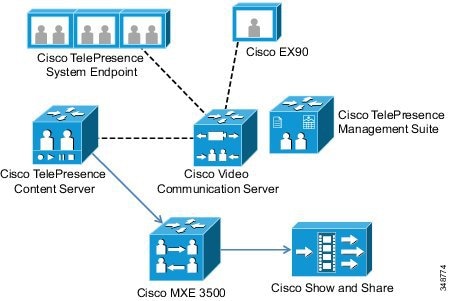
Figure 25-10 illustrates a sample deployment where the Cisco TelePresence Content Server is registered to Cisco VCS. The Cisco TelePresence System endpoint and Cisco EX90 are also registered to Cisco VCS. A Cisco Media Experience Engine (MXE) 3500 is also used to transcode the video recordings and publish to Cisco Show and Share. The TelePresence Content Server records the call between the two endpoints by joining the TelePresence bridge. It then sends the recorded video to the MXE 3500 by means of File Transfer Protocol (FTP). The MXE 3500 transcodes the video and publishes it to the Cisco Show and Share application.
Figure 25-10 Deployment of Cisco TelePresence Content Server with Cisco VCS
For details on the Cisco Telepresence Content Server, refer to the latest version of the Cisco TelePresence Content Server Administration and User Guide, available at
http://www.cisco.com/en/US/products/ps11347/prod_maintenance_guides_list.html
Capacity Planning for Monitoring and Recording
Enabling any type of monitoring and/or call recording impacts the overall Unified Communications system capacity. Some silent monitoring and recording solutions (such as the silent monitoring and recording feature based on Unified CM) consume resources from Unified CM, whereas other solutions such as SPAN or desktop silent monitoring and recording do not. Consider the following points when doing capacity planning for Unified Communications systems with call recording enabled:
- With Unified CM call recording, each recorded call adds two calls to the call processing component BHCA capacity. Forking media from an IP phone or voice gateway consumes resources from Unified CM or the voice gateway, respectively.
- Bandwidth requirements increase when media forking is enabled on IP phones or Cisco Unified Border Element devices to send forked media to the recording server. In case of agent desktop monitoring and recording, the bandwidth utilization can be bursty, depending on how many calls are being monitored or recorded at a given time.
- DSP resource utilization is impacted on Cisco Unified Border Element when doing media forking to Cisco MediaSense.
- Memory utilization on Cisco Unified Border Element increases for each call that is recorded.
- In cases where CTI applications interact with Cisco Unified CM to invoke recording and monitoring, you should consider the Unified CM cluster deployment model and load-balance the CTI applications across the cluster.
Due to the complexity associated with sizing, all deployments must be sized with the Cisco Unified Communications Sizing Tool, available to Cisco employees and partners only (with proper login authentication) at
 Feedback