
Table Of Contents
About Cisco Validated Design (CVD) Program
Cisco Unified Computing System
Cisco C220 M3 Rack Mount Servers
EMC Storage Technologies and Benefits
Memory Configuration Guidelines
ESX/ESXi Memory Management Concepts
Virtual Machine Memory Concepts
Allocating Memory to Virtual Machines
VSPEX VMware Memory Virtualization
VSPEX VMware Storage Virtualization
Network Availability Design - FC-Variant
Network Availability Design - NFS-Variant
Defining the Reference Workload
Applying the Reference Workload
VSPEX Configuration Guidelines
Configuring Cisco Nexus Switches
Prepare UCS FIs and configure UCS Manager
Initial Configuration of Cisco UCS FIs
Configuration for Server Discovery
Upstream/ Global Network Configuration
Configure Server Pool and Qualifying Policy
Configure Service Profile Template
Instantiate Service Profiles from the Service Profile Template
Configure Data-Stores for ESXi images
Install ESXi Servers and vCenter Infrastructure
VMware vCenter Server Deployment
Configuring Cluster, HA and DRS on VMware vCenter
Virtual Networking Configuration
Install and configure Nexus 1000v
Configure Port-Profiles and Add Virtual Machines
Configure storage for VM data stores, install and instantiate VMs from vCenter
Template-Based Deployments for Rapid Provisioning
Validating Cisco Solution for EMC VSPEX VMware Architectures
Verify the Redundancy of the Solution Components
Customer Configuration Data Sheet
Cisco Virtualization Solution for EMC VSPEX with VMware vSphere 5.1 Solution for up to 1000 Virtual MachinesLast Updated: October 18, 2013
Building Architectures to Solve Business Problems
About the Authors
Mehul Bhatt, Cisco SystemsMehul Bhatt has over 12 years of Experience in virtually all layers of computer networking. His focus area includes Unified Compute Systems, network and server virtualization design. Prior to joining Cisco Technical Marketing team, Mehul was Technical Lead at Cisco, Nuova systems and Bluecoat systems. Mehul holds a Masters degree in computer systems engineering and holds various Cisco career certifications.
Prashanto, EMC Corporation
Prashanto has been working for the EMC solutions group for over 3 years. Prashanto is a SME on EMC Storage and Virtualization technologies including VMware and Hyper-V. He has vast amount of experience in end-to-end solution planning and deployments of VSPEX architectures. Prior to joining the solutions group at EMC, Prashanto has interned as a Systems Engineer (EMC) and Software Developer (MBMS Inc.). Prashanto holds a Bachelors degree in Computer Engineering from SUNY Buffalo and will be graduating with a Masters Degree in Computer Science from North Carolina State University in December 2013.
Acknowledgements
For their support and contribution to the design, validation, and creation of the Cisco Validated Design, we would like to thank:
•
Vadiraja Bhatt-Cisco
•
•
•
•
•
•
•
About Cisco Validated Design (CVD) Program
The CVD program consists of systems and solutions designed, tested, and documented to facilitate faster, more reliable, and more predictable customer deployments. For more information visit:
http://www.cisco.com/go/designzone
ALL DESIGNS, SPECIFICATIONS, STATEMENTS, INFORMATION, AND RECOMMENDATIONS (COLLECTIVELY, "DESIGNS") IN THIS MANUAL ARE PRESENTED "AS IS," WITH ALL FAULTS. CISCO AND ITS SUPPLIERS DISCLAIM ALL WARRANTIES, INCLUDING, WITHOUT LIMITATION, THE WARRANTY OF MERCHANTABILITY, FITNESS FOR A PARTICULAR PURPOSE AND NONINFRINGEMENT OR ARISING FROM A COURSE OF DEALING, USAGE, OR TRADE PRACTICE. IN NO EVENT SHALL CISCO OR ITS SUPPLIERS BE LIABLE FOR ANY INDIRECT, SPECIAL, CONSEQUENTIAL, OR INCIDENTAL DAMAGES, INCLUDING, WITHOUT LIMITATION, LOST PROFITS OR LOSS OR DAMAGE TO DATA ARISING OUT OF THE USE OR INABILITY TO USE THE DESIGNS, EVEN IF CISCO OR ITS SUPPLIERS HAVE BEEN ADVISED OF THE POSSIBILITY OF SUCH DAMAGES.
THE DESIGNS ARE SUBJECT TO CHANGE WITHOUT NOTICE. USERS ARE SOLELY RESPONSIBLE FOR THEIR APPLICATION OF THE DESIGNS. THE DESIGNS DO NOT CONSTITUTE THE TECHNICAL OR OTHER PROFESSIONAL ADVICE OF CISCO, ITS SUPPLIERS OR PARTNERS. USERS SHOULD CONSULT THEIR OWN TECHNICAL ADVISORS BEFORE IMPLEMENTING THE DESIGNS. RESULTS MAY VARY DEPENDING ON FACTORS NOT TESTED BY CISCO.
The Cisco implementation of TCP header compression is an adaptation of a program developed by the University of California, Berkeley (UCB) as part of UCB's public domain version of the UNIX operating system. All rights reserved. Copyright © 1981, Regents of the University of California.
Cisco and the Cisco Logo are trademarks of Cisco Systems, Inc. and/or its affiliates in the U.S. and other countries. A listing of Cisco's trademarks can be found at http://www.cisco.com/go/trademarks. Third party trademarks mentioned are the property of their respective owners. The use of the word partner does not imply a partnership relationship between Cisco and any other company. (1005R)
Any Internet Protocol (IP) addresses and phone numbers used in this document are not intended to be actual addresses and phone numbers. Any examples, command display output, network topology diagrams, and other figures included in the document are shown for illustrative purposes only. Any use of actual IP addresses or phone numbers in illustrative content is unintentional and coincidental.
© 2013 Cisco Systems, Inc. All rights reserved.
Cisco Virtualization Solution for EMC VSPEX with VMware vSphere 5.1 Solution for up to 1000 Virtual Machines
Executive Summary
Cisco solution for EMC VSPEX is a pre-validated and modular architecture built with proven best of-breed technologies to create complete end-to-end virtualization solutions that enable you to make an informed decision while choosing the hypervisor, compute, storage and networking layers. VSPEX drastically reduces server virtualization planning and configuration burdens. VSPEX infrastructures accelerate your IT Transformation by enabling faster deployments, greater flexibility of choice, efficiency, and lower risk. This Cisco Validate Design document focuses on the VSPEX VMware architecture for mid-market business segments with less than 1000 typical Virtual Machines load.
Introduction
Virtualization is a key and critical strategic deployment model for reducing the Total Cost of Ownership (TCO) and achieving better utilization of the platform components like hardware, software, network and storage. However, choosing an appropriate platform for virtualization can be challenging. Virtualization platforms should be flexible, reliable, and cost effective to facilitate the deployment of various enterprise applications. In a virtualization platform to utilize compute, network, and storage resources effectively, the ability to slice and dice the underlying platform is essential to size to the application requirements. The Cisco solution for the EMC VSPEX provides a very simplistic yet fully integrated and validated infrastructure to deploy VMs in various sizes to suit various application needs.
Target Audience
The reader of this document is expected to have the necessary training and background to install and configure VMware vSphere, EMC VNX series storage arrays, and Cisco Unified Computing System (UCS) and UCS Manager. External references are provided where ever applicable and it is recommended that the reader be familiar with these documents.
Readers are also expected to be familiar with the infrastructure and database security policies of the customer installation.
Purpose of this Document
This document describes the steps required to deploy and configure a Cisco solution for EMC VSPEX for VMware architectures to a level that will allow for confirmation that the basic components and connections are working correctly. The document covers VMware architectures for SMBs, typically for 1000 VMs or less. This document showcases two variants of the solution:
•
•
While readers of this document are expected to have sufficient knowledge to install and configure the products used, configuration details that are required for deploying these solutions are specifically mentioned.
Business Needs
The VSPEX solutions are built with proven best-of-breed technologies to create complete virtualization solutions that enable you to make an informed decision in the hypervisor, server, and networking layers. The VSPEX infrastructures accelerate your IT transformation by enabling faster deployments, greater flexibility of choice, efficiency, and lower risk.
Business applications are moving into the consolidated compute, network, and storage environment. The Cisco solution for the EMC VSPEX using VMware reduces the complexity of configuring every component of a traditional deployment model. The complexity of integration management is reduced while maintaining the application design and implementation options. Administration is unified, while process separation can be adequately controlled and monitored. The following are the business needs for the Cisco solution for EMC VSPEX VMware architectures:
•
•
•
•
Solution Overview
The Cisco solution for EMC VSPEX using VMware vSphere 5.1 provides an end-to-end architecture with Cisco, EMC, VMware, and Microsoft technologies that demonstrate support for up to 1000 generic virtual machines and provide high availability and server redundancy.
The following are the components used for the design and deployment:
•
•
•
•
•
•
•
•
•
•
•
•
•
The solution is designed to host scalable, and mixed application workloads for up to 1000 reference virtual machines.
Technology Overview
Cisco Unified Computing System
The Cisco Unified Computing System is a next-generation data center platform that unites compute, network, and storage access. The platform, optimized for virtual environments, is designed using open industry-standard technologies and aims to reduce total cost of ownership (TCO) and increase business agility. The system integrates a low-latency; lossless 10 Gigabit Ethernet unified network fabric with enterprise-class, x86-architecture servers. It is an integrated, scalable, multi chassis platform in which all resources participate in a unified management domain.
The main components of Cisco Unified Computing System are:
•
•
•
•
The Cisco Unified Computing System is designed to deliver:
•
•
•
•
Cisco UCS Manager
Cisco UCS Manager provides unified, embedded management of all software and hardware components of the Cisco Unified Computing System through an intuitive GUI, a command line interface (CLI), or an XML API. The Cisco UCS Manager provides unified management domain with centralized management capabilities and controls multiple chassis and thousands of virtual machines.
Cisco UCS Fabric Interconnect
The Cisco® UCS 6200 Series Fabric Interconnect is a core part of the Cisco Unified Computing System, providing both network connectivity and management capabilities for the system. The Cisco UCS 6200 Series offers line-rate, low-latency, lossless 10 Gigabit Ethernet, Fibre Channel over Ethernet (FCoE) and Fibre Channel functions.
The Cisco UCS 6200 Series provides the management and communication backbone for the Cisco UCS B-Series Blade Servers and Cisco UCS 5100 Series Blade Server Chassis. All chassis, and therefore all blades, attached to the Cisco UCS 6200 Series Fabric Interconnects become part of a single, highly available management domain. In addition, by supporting unified fabric, the Cisco UCS 6200 Series provides both the LAN and SAN connectivity for all blades within its domain.
From a networking perspective, the Cisco UCS 6200 Series uses a cut-through architecture, supporting deterministic, low-latency, line-rate 10 Gigabit Ethernet on all ports, 1Tb switching capacity, 160 Gbps bandwidth per chassis, independent of packet size and enabled services. The product family supports Cisco low-latency, lossless 10 Gigabit Ethernet unified network fabric capabilities, which increase the reliability, efficiency, and scalability of Ethernet networks. The Fabric Interconnect supports multiple traffic classes over a lossless Ethernet fabric from a blade server through an interconnect. Significant TCO savings come from an FCoE-optimized server design in which network interface cards (NICs), host bus adapters (HBAs), cables, and switches can be consolidated.
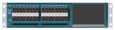
Cisco UCS 6248UP Fabric Interconnect
The Cisco UCS 6248UP 48-Port Fabric Interconnect is a one-rack-unit (1RU) 10 Gigabit Ethernet, FCoE and Fiber Channel switch offering up to 960-Gbps throughput and up to 48 ports. The switch has 32 1/10-Gbps fixed Ethernet, FCoE and FC ports and one expansion slot.
Figure 1 Cisco UCS 6248UP Fabric Interconnect
Cisco UCS Fabric Extenders
Fabric Extenders are zero-management, low-cost, low-power consuming devices that distribute the system's connectivity and management planes into rack and blade chassis to scale the system without complexity. Designed never to lose a packet, Cisco fabric extenders eliminate the need for top-of-rack Ethernet and Fibre Channel switches and management modules, dramatically reducing infrastructure cost per server.
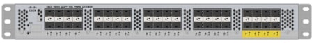
Cisco UCS 2232PP Fabric Extender
The Cisco Nexus® 2000 Series Fabric Extenders comprise a category of data center products designed to simplify data center access architecture and operations. The Cisco Nexus 2000 Series uses the Cisco® Fabric Extender architecture to provide a highly scalable unified server-access platform across a range of 100 Megabit Ethernet, Gigabit Ethernet, 10 Gigabit Ethernet, unified fabric, copper and fiber connectivity, rack, and blade server environments. The platform is ideal to support today's traditional Gigabit Ethernet while allowing transparent migration to 10 Gigabit Ethernet, virtual machine-aware unified fabric technologies.
The Cisco Nexus 2000 Series Fabric Extenders behave as remote line cards for a parent Cisco Nexus switch or Fabric Interconnect. The fabric extenders are essentially extensions of the parent Cisco UCS Fabric Interconnect switch fabric, with the fabric extenders and the parent Cisco Nexus switch together forming a distributed modular system. This architecture enables physical topologies with the flexibility and benefits of both top-of-rack (ToR) and end-of-row (EoR) deployments.
Today's data centers must have massive scalability to manage the combination of an increasing number of servers and a higher demand for bandwidth from each server. The Cisco Nexus 2000 Series increases the scalability of the access layer to accommodate both sets of demands without increasing management points within the network.
Figure 2 Cisco UCS 2232PP Fabric Extender
Cisco C220 M3 Rack Mount Servers
Building on the success of the Cisco UCS C220 M3 Rack Servers, the enterprise-class Cisco UCS C220 M3 server further extends the capabilities of the Cisco Unified Computing System portfolio in a 1-rack-unit (1RU) form factor. And with the addition of the Intel® Xeon® processor E5-2600 V2.
Figure 3 Cisco UCS C220 M3 Rack Mount Server
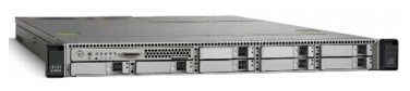
The Cisco UCS C220 M3 also offers up to 256 GB of RAM, eight drives or SSDs, and two 1GE LAN interfaces built into the motherboard, delivering outstanding levels of density and performance in a compact package.
Cisco UCS Blade Chassis
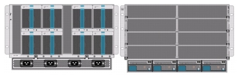
The Cisco UCS 5100 Series Blade Server Chassis is a crucial building block of the Cisco Unified Computing System, delivering a scalable and flexible blade server chassis.
The Cisco UCS 5108 Blade Server Chassis, is six rack units (6RU) high and can mount in an industry-standard 19-inch rack. A single chassis can house up to eight half-width Cisco UCS B-Series Blade Servers and can accommodate both half-width and full-width blade form factors.
Four single-phase, hot-swappable power supplies are accessible from the front of the chassis. These power supplies are 92 percent efficient and can be configured to support non-redundant, N+ 1 redundant and grid-redundant configurations. The rear of the chassis contains eight hot-swappable fans, four power connectors (one per power supply), and two I/O bays for Cisco UCS 2204XP Fabric Extenders.
A passive mid-plane provides up to 40 Gbps of I/O bandwidth per server slot and up to 80 Gbps of I/O bandwidth for two slots. The chassis is capable of supporting future 40 Gigabit Ethernet standards. The Cisco UCS Blade Server Chassis is shown in Figure 4.
Figure 4 Cisco Blade Server Chassis (front and back view)
Cisco UCS Blade Servers
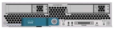
Delivering performance, versatility and density without compromise, the Cisco UCS B200 M3 Blade Server addresses the broadest set of workloads, from IT and Web Infrastructure through distributed database.
Building on the success of the Cisco UCS B200 M2 blade servers, the enterprise-class Cisco UCS B200 M3 server, further extends the capabilities of Cisco's Unified Computing System portfolio in a half blade form factor. The Cisco UCS B200 M3 server harnesses the power and efficiency of the Intel Xeon E5-2600 V2 processor product family, up to 768 GB of RAM, 2 drives or SSDs and up to 2 x 20 GbE to deliver exceptional levels of performance, memory expandability and I/O throughput for nearly all applications. In addition, the Cisco UCS B200 M3 blade server offers a modern design that removes the need for redundant switching components in every chassis in favor of a simplified top of rack design, allowing more space for server resources, providing a density, power and performance advantage over previous generation servers. The Cisco UCS B200M3 Server is shown in Figure 5.
Figure 5 Cisco UCS B200 M3 Blade Server
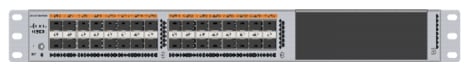
Cisco Nexus 5548UP Switch
The Cisco Nexus 5548UP is a 1RU 1 Gigabit and 10 Gigabit Ethernet switch offering up to 960 gigabits per second throughput and scaling up to 48 ports. It offers 32 1/10 Gigabit Ethernet fixed enhanced Small Form-Factor Pluggable (SFP+) Ethernet/FCoE or 1/2/4/8-Gbps native FC unified ports and three expansion slots. These slots have a combination of Ethernet/FCoE and native FC ports. The Cisco Nexus 5548UP switch is shown in Figure 6.
Figure 6 Cisco Nexus 5548UP switch
Cisco I/O Adapters
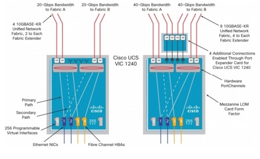
Cisco UCS Blade Servers support various Converged Network Adapter (CNA) options. Cisco UCS Virtual Interface Card (VIC) 1240 is used in this EMC VSPEX solution.
The Cisco UCS Virtual Interface Card 1240 is a 4-port 10 Gigabit Ethernet, Fibre Channel over Ethernet (FCoE)-capable modular LAN on motherboard (mLOM) designed exclusively for the M3 generation of Cisco UCS B-Series Blade Servers. When used in combination with an optional Port Expander, the Cisco UCS VIC 1240 capabilities can be expanded to eight ports of 10 Gigabit Ethernet.
The Cisco UCS VIC 1240 enables a policy-based, stateless, agile server infrastructure that can present up to 256 PCIe standards-compliant interfaces to the host that can be dynamically configured as either network interface cards (NICs) or host bus adapters (HBAs). In addition, the Cisco UCS VIC 1240 supports Cisco Data Center Virtual Machine Fabric Extender (VM-FEX) technology, which extends the Cisco UCS fabric interconnect ports to virtual machines, simplifying server virtualization deployment.
Figure 7 Cisco UCS VIC 1240
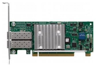
The Cisco UCS rack mount server has various Converged Network Adapters (CNA) options. The UCS 1225 Virtual Interface Card (VIC) option is used in this Cisco Validated Design.
A Cisco® innovation, the Cisco UCS Virtual Interface Card (VIC) 1225 is a dual-port Enhanced Small Form-Factor Pluggable (SFP+) 10 Gigabit Ethernet and Fibre Channel over Ethernet (FCoE)-capable PCI Express (PCIe) card designed exclusively for Cisco UCS C-Series Rack Servers.
UCS 1225 VIC provides the capability to create multiple vNICs (up to 128) on the CNA. This allows complete I/O configurations to be provisioned in virtualized or non-virtualized environments using just-in-time provisioning, providing tremendous system flexibility and allowing consolidation of multiple physical adapters.
System security and manageability is improved by providing visibility and portability of network policies and security all the way to the virtual machines. Additional 1225 features like VM-FEX technology and pass-through switching, minimize implementation overhead and complexity.
Figure 8 Cisco UCS 1225 VIC
Nexus 1000v Virtual Switch
Nexus 1000v is a virtual Ethernet switch with two components:
· Virtual Supervisor Module (VSM)—The control plane of the virtual switch that runs NX OS.
· Virtual Ethernet Module (VEM)—A virtual line card embedded into each VMware vSphere hypervisor host (ESXi).
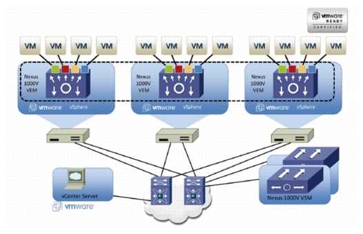
Virtual Ethernet Modules across multiple ESXi hosts form a virtual Distributed Switch (vDS). Using the Cisco vDS VMware plug-in, the VIC provides a solution that is capable of discovering the Dynamic Ethernet interfaces and registering all of them as uplink interfaces for internal consumption of the vDS. The vDS component on each host discovers the number of uplink interfaces that it has and presents a switch to the virtual machines running on the host. All traffic from an interface on a virtual machine is sent to the corresponding port of the vDS switch. The traffic is then sent out to physical link of the host using the special uplink port-profile. This vDS implementation guarantees consistency of features and better integration of host virtualization with rest of the Ethernet fabric in the data center.
Figure 9 Nexus 1000v Virtual Distributed Switch Architecture
UCS 2.1 Singe Wire Management
Cisco UCS Manager 2.1 supports an additional option to integrate the C-Series Rack-Mount Server with Cisco UCS Manager called "single-wire management". This option enables Cisco UCS Manager to manage the C-Series Rack-Mount Servers using a single 10 GE link for both management traffic and data traffic. When you use the single-wire management mode, one host facing port on the FEX is sufficient to manage one rack-mount server, instead of the two ports you will use in the Shared-LOM mode. Cisco VIC 1225, Cisco UCS 2232PP FEX and Single-Wire management feature of UCS 2.1 tremendously increases the scale of C-Series server manageability. By consuming as little as one port on the UCS Fabric Interconnect, you can manage up to 32 C-Series server using single-wire management feature.
UCS Differentiators
Cisco's Unified Compute System is revolutionizing the way servers are managed in data-center. Following are the unique differentiators of UCS and UCS Manager.
1.
2.
3.
4.
5.
6.
7.
8.
9.
10.
11.
12.
13.
14.
VMware vSphere 5.1
VMware vSphere 5.1 is a next-generation virtualization solution from VMware which builds upon vSphere5.0 and provides greater levels of scalability, security, and availability to virtualized environments. vSphere 5.1 offers improvements in performance and utilization of CPU, memory, and I/O. It also offers users the option to assign up to thirty two virtual CPU to a virtual machine—giving system administrators more flexibility in their virtual server farms as processor-intensive workloads continue to increase.
The vSphere 5.1 provides the VMware vCenter Server that allows system administrators to manage their ESXi hosts and virtual machines on a centralized management platform. With the Cisco Nexus 1000v switch integrated into the vCenter Server, deploying and administering virtual machines is similar to deploying and administering physical servers. Network administrators can continue to own the responsibility for configuring and monitoring network resources for virtualized servers as they did with physical servers. System administrators can continue to "plug-in" their virtual machines into the network ports that have Layer 2 configurations, port access and security policies, monitoring features, and so on, that have been pre-defined by the network administrators; in the same way they need to plug in their physical servers to a previously-configured access switch. In this virtualized environment, the network port configuration/policies move with the virtual machines when the virtual machines are migrated to different server hardware.
EMC Storage Technologies and Benefits
This document describes the steps required to deploy and configure a Cisco solution for EMC VSPEX with VMware architectures. This architecture has two variants:
•
•
The EMC VNX™ family is optimized for virtual applications delivering industry-leading innovation and enterprise capabilities for file, block, and object storage in a scalable, easy-to-use solution. This next-generation storage platform combines powerful and flexible hardware with advanced efficiency, management, and protection software to meet the demanding needs of today's enterprises.
VNX series is designed to meet the high-performance, high-scalability requirements of midsize and large enterprises. The EMC VNX storage arrays are multi-protocol platform that can support the iSCSI, NFS, Fibre Channel, and CIFS protocols depending on the customer's specific needs. This solution was validated using NFS and FC for data storage of virtual machines and Fibre Channel for hypervisor SAN boot.
VNX series storage arrays have the following customer benefits:
•
•
•
•
•
Software Suites
The following are the available EMC software suites:
•
•
•
Software Packs
Total Value Pack—Includes all protection software suites, and the Security and Compliance Suite.
This is the available EMC protection software pack.
EMC Avamar
EMC's Avamar® data deduplication technology seamlessly integrates into virtual environments, providing rapid backup and restoration capabilities. Avamar's deduplication results in vastly less data traversing the network, and greatly reduces the amount of data being backed up and stored; resulting in storage, bandwidth and operational savings.
The following are the two most common recovery requests used in backup and recovery:
•
•
The Avamar System State protection functionality adds backup and recovery capabilities in both of these scenarios.
Architectural Overview
This CVD focuses on the architecture for EMC VSPEX for VMware private cloud, targeted for mid-market segment, using VNX storage arrays. There are two variants of the architecture: FC-variant and NFS-variant. FC-variant of the architecture uses UCS 2.1(3a) with combined B-series and C-series servers with VNX5400 directly attached to UCS fabric interconnect. NFS-variant of the architecture uses UCS 2.1(3a) with B-series and C-series servers with VNX5600 or VNX5800 storage array attached to the Nexus 5548 switches. In both variants, the C220 M3 servers are connected with single-wire management feature. VMware vSphere 5.1 is used as server virtualization architecture. FC-variant of architecture show cases VMware's native virtual switching, while NFS-variant of architecture show cases Cisco Nexus 1000v based virtual switches. However, either architecture can use any of the virtual switching components.
Table 1 lists the various hardware and software components which occupies different tiers of the Cisco solution for EMC VSPEX VMware architectures under test.
Table 2 outlines the B200M3 or C220M3 server configuration (per server basis) across the two variants of VMware architectures.
Both the variants of architecture assume that there is an existing infrastructure/ management network available where a virtual machine hosting vCenter server and Windows Active Directory/ DNS server are present.
The required number of C or B series servers and storage array type change depending on number of virtual machines. Table 3 highlights the change in hardware components, as required by different scale. Typically, 50 reference Virtual Machines are deployed per server.
Figure 10 and Figure 11 show a high level Cisco solution for EMC VSPEX VMware FC-variant and NFS-variant architectures respectively.
Figure 10 Reference Architecture for FC-Variant
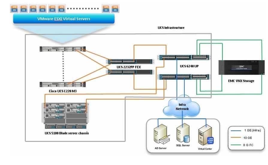
Figure 11 Reference Architecture for NFS-Variant
Following are the key design points of the architectures for mid-market segment:
•
•
•
This design does not dictate or require any specific layout of infrastructure network. The vCenter server, Microsoft AD server and Microsoft SQL server are hosted on infrastructure network. However, design does require accessibility of certain VLANs from the infrastructure network to reach the servers.
ESXi 5.1 is used as hypervisor operating system on each server and is installed on SAN LUNs in both the architectures. However, virtual machines' storage is accessed through FC or NFS protocols depending on the architecture. Typical load is 50 reference virtual machines per server.
Memory Configuration Guidelines
This section provides guidelines for allocating memory to the virtual machines. The guidelines outlined here take into account vSphere memory overhead and the virtual machine memory settings.
ESX/ESXi Memory Management Concepts
vSphere virtualizes guest physical memory by adding an extra level of address translation. Shadow page tables make it possible to provide this additional translation with little or no overhead. Managing memory in the hypervisor enables the following:
•
•
•
For more information about vSphere memory management concepts, see the VMware vSphere Resource Management Guide at: http://www.vmware.com/files/pdf/perf-vsphere-memory_management.pdf
Virtual Machine Memory Concepts
Figure 12 shows the use of memory settings parameters in the virtual machine.
Figure 12 Virtual Machine Memory Settings
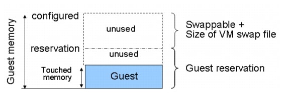
The vSphere memory settings for a virtual machine include the following parameters:
•
•
•
Allocating Memory to Virtual Machines
Memory sizing for a virtual machine in VSPEX architectures is based on many factors. With the number of application services and use cases available determining a suitable configuration for an environment requires creating a baseline configuration, testing, and making adjustments, as discussed later in this paper. Table 4 outlines the resources used by a single virtual machine:
Following are the recommended best practices:
•
•
•
–
–
–
Storage Guidelines
VSPEX architecture for VMware VMs for mid-market segment uses FC or NFS to access storage arrays. FC is used with smaller scale with VNX5400 storage array, while NFS is used with VNX5600 or VNX5800 storage array. vSphere provides many features that take advantage of EMC storage technologies such as auto discovery of storage resources and ESXi hosts in vCenter and VNX respectively. Features such as VMware vMotion, VMware HA, and VMware Distributed Resource Scheduler (DRS) use these storage technologies to provide high availability, resource balancing, and uninterrupted workload migration.
Storage Protocol Capabilities
VMware vSphere provides vSphere and storage administrators with the flexibility to use the storage protocol that meets the requirements of the business. This can be a single protocol datacenter wide, such as NFS, or multiple protocols for tiered scenarios such as using Fibre Channel for high-throughput storage pools and NFS for high-capacity storage pools.
For VSPEX solution on vSphere NFS is a recommended option because of its simplicity in deployment.
For more information, see the VMware white paper Comparison of Storage Protocol Performance in VMware vSphere 5: http://www.vmware.com/files/pdf/perf_vsphere_storage_protocols.pdf
Storage Best Practices
Following are the vSphere storage best practices:
•
•
•
•
•
VSPEX VMware Memory Virtualization
VMware vSphere 5.1 has a number of advanced features that help to maximize performance and overall resources utilization. This section describes the performance benefits of some of these features for the VSPEX deployment.
Memory Compression
Memory over-commitment occurs when more memory is allocated to virtual machines than is physically present in a VMware ESXi host. Using sophisticated techniques, such as ballooning and transparent page sharing, ESXi is able to handle memory over-commitment without any performance degradation. However, if more memory than that is present on the server is being actively used, ESXi might resort to swapping out portions of a VM's memory.
For more details about Vsphere memory management concepts, see the VMware Vsphere Resource Management Guide at: http://www.VMware.com/files/pdf/mem_mgmt_perf_Vsphere5.pdf
Virtual Networking
NFS-variant architecture demonstrates use and benefits of Nexus 1000v virtual switching technology. Each B200 M3 blade server and C220 M3 rack server has one physical adapter with two 10 GE links going to fabric A and fabric B for high availability. Cisco UCS VIC 1225 or 1240 presents four virtual Network Interface Cards (vNICs) to the hypervisor, two vNICs per fabric path. In FC-variant, the Cisco UCS VIC 1225 adapter also presents two virtual Host Bus Adapters (vHBAs) to the hypervisor, one per fabric path. The MAC addresses to these vNICs are assigned using MAC address pool defined on the UCS Manager. The vNICs are used in active-active configuration for load-balancing and high-availability. Following are vSphere networking best practices implemented in this architecture:
•
–
–
•
•
•
VSPEX VMware Storage Virtualization
Disk provisioning on the EMC VNX series requires administrators to choose disks for each of the storage pools.
Storage Layout
The architecture diagram in this section shows the physical disk layout. Disk provisioning on the VNX series is simplified through the use of wizards, so that administrators do not choose which disks belong to a given storage pool. The wizard may choose any available disk of the proper type, regardless of where the disk physically resides in the array.
Figure 13 shows storage architecture for 300 virtual machines on VNX5400 for FC-variant of architecture.
Figure 13 Storage Architecture for 300 VMs on EMC VNX5400
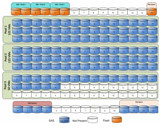
Figure 14 shows storage architecture for 600 virtual machines on VNX5600 for NFS-variant of architecture.
Figure 14 Storage Architecture for 600 VMs on EMC VNX5600
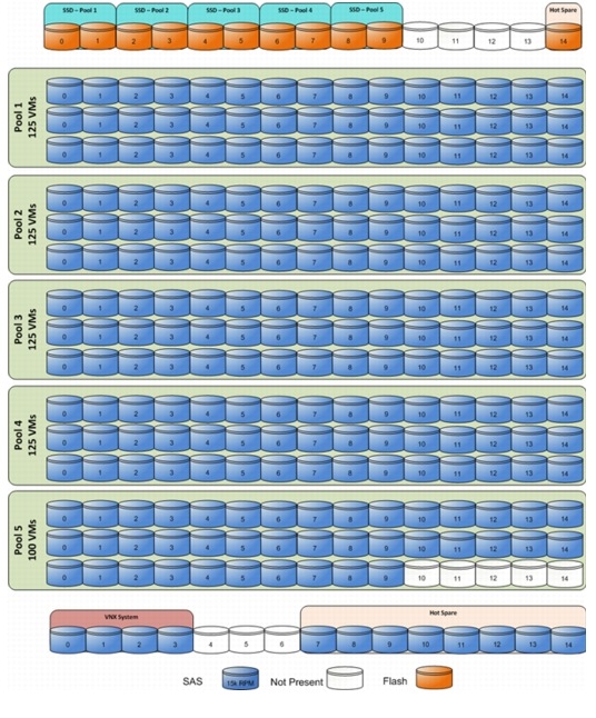
Figure 15 shows storage architecture for 1000 virtual machines on VNX5800 for NFS-variant of architecture.
Figure 15 Storage Architecture for 1000 VMs on EMC VNX5800
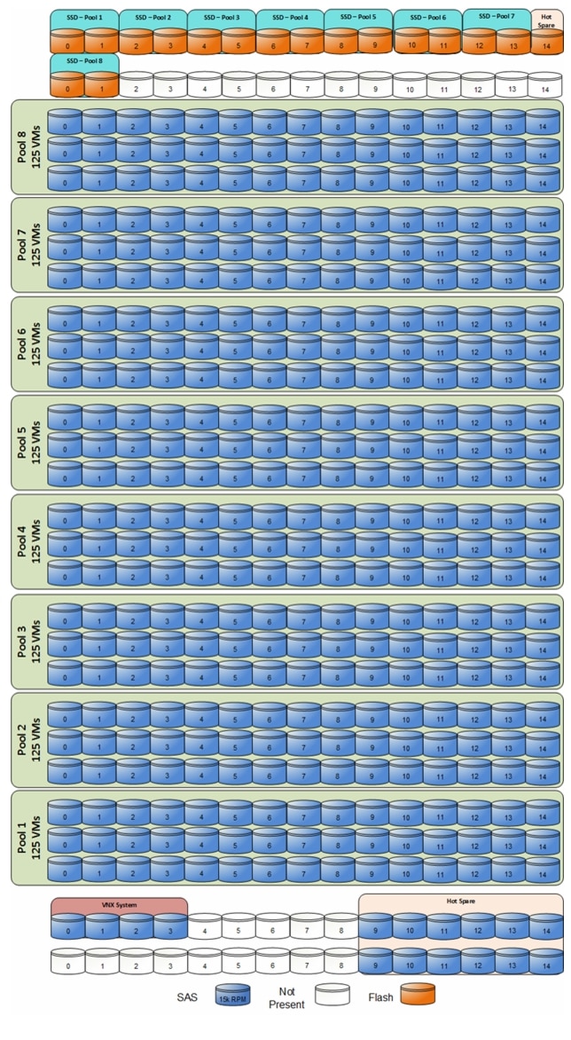
Table provides the data stores size for various architectures shown in Figure 13, Figure 14, and Figure 15.
The VNX family storage array is designed for five 9s availability by using redundant components throughout the array. All of the array components are capable of continued operation in case of hardware failure. The RAID disk configuration on the array provides protection against data loss due to individual disk failures, and the available hot spare drives can be dynamically allocated to replace a failing disk.
Storage Virtualization
NFS is a cluster file system that provides UDP based stateless storage protocol to access storage across multiple hosts over the network. Each virtual machine is encapsulated in a small set of files and NFS datastore mount points are used for the operating system partitioning and data partitioning.
It is preferable to deploy virtual machine files on shared storage to take advantage of VMware VMotion, VMware High Availability™ (HA), and VMware Distributed Resource Scheduler™ (DRS). This is considered a best practice for mission-critical deployments, which are often installed on third-party, shared storage management solutions.
Service Profile Design
This architecture implements following design steps to truly achieve stateless computing on the servers:
•
•
–
–
–
All of these identifiers are defined in their respective identifier pools and the pool names are referred in the service profile template.
•
•
•
Given this design and capabilities of UCS and UCS Manager, a new server can be procured within minutes if the scale needs to be increased or if a server needs to be replaced by different hardware. In case, if a server has physical fault (faulty memory, or PSU or fan, for example), using following steps, a new server can be procured within minutes:
•
•
•
•
•
Thus, the architecture achieves the true statelessness of the computing in the data-center. If there are enough identifiers in all the id-pools, and if more servers are attached to UCS system in future, more service profiles can be derived from the service profile template and the private cloud infrastructure can be easily expanded. We would demonstrate that blade and rack servers can be added in the same server pool.
Network Availability Design - FC-Variant
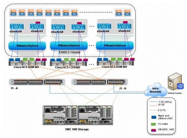
Figure 16 shows the logical layout of FC-variant architecture. The following are the key aspects of this solution:
•
•
•
•
•
Storage is made highly available by deploying following practices:
•
•
•
•
•
Figure 16 Logical Layout of FC-Variant Architecture
Network Availability Design - NFS-Variant
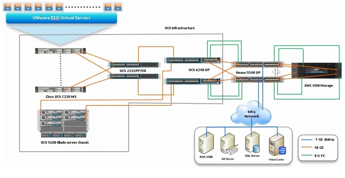
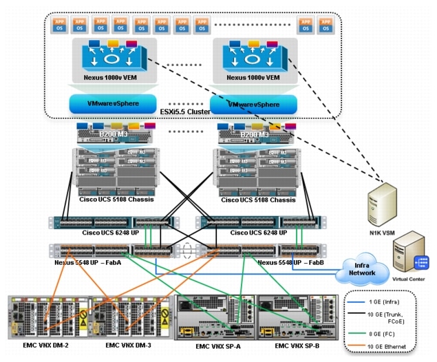
Following figure demonstrates logical layout of the architecture. Following are the key aspects of this solution:
•
•
•
•
•
•
Storage is made highly available by deploying following practices:
•
•
•
•
•
•
Figure 17 Logical Layout of NFS-Variant Architecture
Jumbo MTU
Jumbo MTU (size 9000) is used for following two types of traffic in this architecture:
•
•
Both of these traffic types are "bulk transfer" traffic, and larger MTU significantly improves the performance. Jumbo MTU must be configured end-to-end to ensure that IP packets are not fragmented by intermediate network nodes. Following is the checklist of the end-points where the jumbo MTU needs to be configured:
1.
2.
3.
4.
5.
6.
Sizing Guidelines
In any discussion about virtual infrastructures, it is important to first define a reference workload. Not all servers perform the same tasks, and it is impractical to build a reference that takes into account every possible combination of workload characteristics.
Defining the Reference Workload
To simplify the discussion, we have defined a representative customer reference workload. By comparing your actual customer usage to this reference workload, you can extrapolate which reference architecture to choose.
For the VSPEX solutions, the reference workload was defined as a single virtual machine. This virtual machine has the characteristics shown in Table 4.
This specification for a virtual machine is not intended to represent any specific application. Rather, it represents a single common point of reference to measure other virtual machines.
Applying the Reference Workload
When considering an existing server which will move into a virtual infrastructure, you have the opportunity to gain efficiency by right-sizing the virtual hardware resources assigned to that system.
The reference architectures create a pool of resources sufficient to host a target number of reference virtual machines as described above. It is entirely possible that customer virtual machines may not exactly match the specifications above. In that case, you can say that a single specific customer virtual machine is the equivalent of some number of reference virtual machines, and assume that number of virtual machines have been used in the pool. You can continue to provision virtual machines from the pool of resources until it is exhausted. Consider these examples:
Example 1 Custom Built Application
A small custom-built application server needs to move into this virtual infrastructure.
The physical hardware supporting the application is not being fully utilized at present. A
careful analysis of the existing application reveals that the application can use one
processor, and needs 3GB of memory to run normally. The IO workload ranges between 4 IOPS
at idle time to 15 IOPS when busy. The entire application is only using about 30GB on
local hard drive storage.
Based on these numbers, following resources are needed from the resource pool:- CPU resources for one VM- Memory resources for two VMs- Storage capacity for one VM- IOPS for one VMIn this example, a single virtual machine uses the resources of two of the reference VMs. Once this VM is deployed, the solution's new capability would be 298 VMs.Example 2 Point of Sale System
The database server for a customer's point-of-sale system needs to move into this virtual
infrastructure. It is currently running on a physical system with four CPUs and 16GB of
memory. It uses 200GB storage and generates 200 IOPS during an average busy cycle.
The following resources that are needed from the resource pool to virtualize this application:- CPUs of four reference VMs- Memory of eight reference VMs- Storage of two reference VMs- IOPS of eight reference VMsIn this case the one virtual machine uses the resources of eight reference virtual machines. Once this VM is deployed, the solution's new capability would be 292 VMs.Example 3 Web Server
The customer's web server needs to move into this virtual infrastructure. It is currently
running on a physical system with two CPUs and 8GB of memory. It uses 25GB of storage and
generates 50 IOPS during an average busy cycle.
The following resources that are needed from the resource pool to virtualize this application:- CPUs of two reference VMs- Memory of four reference VMs- Storage of one reference VMs- IOPS of two reference VMsIn this case the virtual machine would use the resources of four reference virtual machines. Once this VM is deployed, the solution's new capability would be 296 VMs.Example 4 Decision Support Database
The database server for a customer's decision support system needs to move into this
virtual infrastructure. It is currently running on a physical system with 10 CPUs and 48GB
of memory. It uses 5TB of storage and generates 700 IOPS during an average busy cycle.
The following resources that are needed from the resource pool to virtualize this application:- CPUs of ten reference VMs- Memory of 24 reference VMs- Storage of 52 reference VMs- IOPS of 28 reference VMsIn this case the one virtual machine uses the resources of 52 reference virtual machines. If this was implemented on a resource pool for 300 virtual machines, there are 248 virtual machines of capability remaining in the pool.Summary of Example
The four examples show the flexibility of the resource pool model. In all the four cases the workloads simply reduce the number of available resources in the pool. If all four examples were implemented on the same virtual infrastructure, with an initial capacity of 300 virtual machines they can all be implemented, leaving the capacity of 236 reference virtual machines in the resource pool.
In more advanced cases, there may be tradeoffs between memory and I/O or other relationships where increasing the amount of one resource, decreases the need for another. In these cases, the interactions between resource allocations become highly complex, and are out of the scope of this document. However, when a change in the resource balance is observed, and the new level of requirements is known; these virtual machines can be added to the infrastructure using the method described in the above examples.
VSPEX Configuration Guidelines
This sections provides the procedure to deploy the Cisco solution for EMC VSPEX VMware architecture.
Follow these steps to configure the Cisco solution for EMC VSPEX VMware architectures:
1.
2.
3.
4.
5.
6.
7.
8.
9.
10.
These steps are described in detail in the following sections.
Pre-deployment Tasks
Pre-deployment tasks include procedures that do not directly relate to environment installation and configuration, but whose results will be needed at the time of installation. Examples of pre-deployment tasks are collection of hostnames, IP addresses, VLAN IDs, license keys, installation media, and so on. These tasks should be performed before the customer visit to decrease the time required onsite.
•
•
•
Customer Configuration Data
To reduce the onsite time, information such as IP addresses and hostnames should be assembled as part of the planning process.
The section Customer Configuration Data Sheet provides tabulated record of relevant information (to be filled at the customer's end). This form can be expanded or contracted as required, and information may be added, modified, and recorded as the deployment progresses.
Additionally, complete the VNX Series Configuration Worksheet, available on the EMC online support website, to provide the most comprehensive array-specific information.
Connect Network Cables
See the Cisco Nexus 5548UP, UCS FI, FEX, Blade server chassis, B-series and C-series server and EMC VNX storage array configuration guide for detailed information about how to mount the hardware on the rack. Following diagrams show connectivity details for the VSPEX VMware architecture covered in this document.
Connectivity for FC-Variant:
As shown in the following figure, there are four major cabling sections in this architecture:
•
•
•
•
Figure 18 Detailed Connectivity Diagram of the FC-Variant Architecture
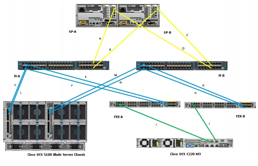
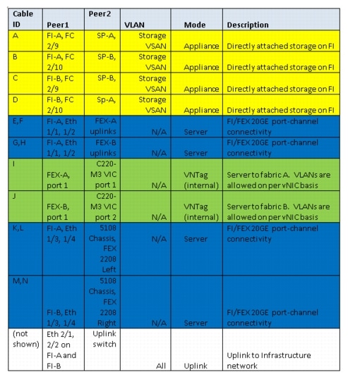
Figure 19 elaborates the detailed cable connectivity for the architecture.
Figure 19 Connectivity Details of FC-Variant Architecture
Connectivity for NFS-Variant
As shown in the following figure, there are four major cabling sections in this architecture:
•
•
•
•
Figure 20 Detailed Connectivity Diagram of the NFS-Variant Architecture
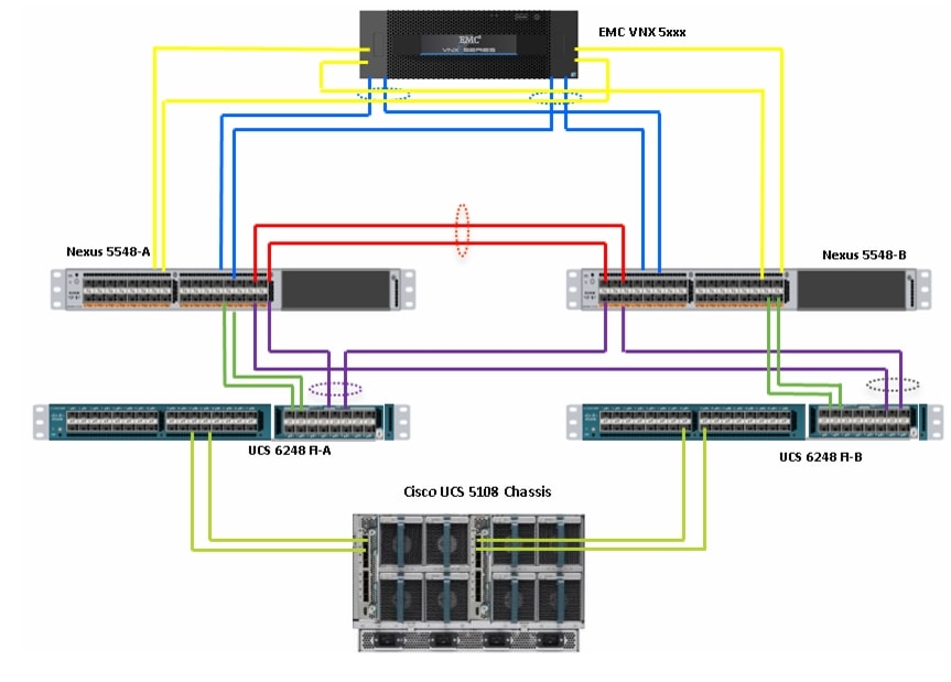
Figure 21 elaborates the detailed cable connectivity for the architecture.
Figure 21 Ethernet Cable Connectivity Details of NFS-Variant Architecture
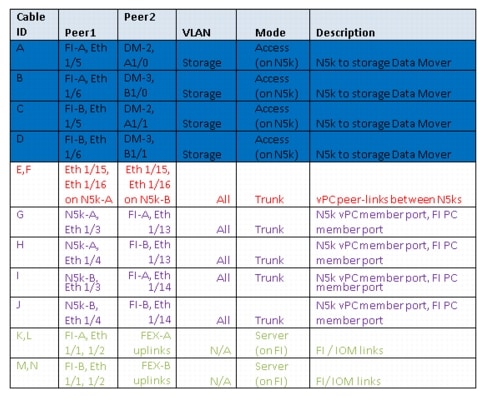
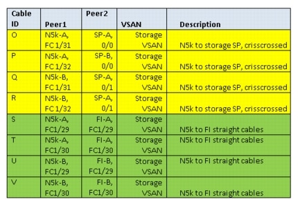
Figure 22 FC Cable Connectivity Details for NFS-Variant Architecture
By connecting all the cables as outlined above, and you would be ready to configure Cisco Nexus 5548UP Switch, EMC VNX Series Storage Array and Cisco UCS Managaer.
Configuring Cisco Nexus Switches
This section explains switch configuration needed for the Cisco solution for EMC VSPEX VMware architectures. For information on configuring password, and management connectivity, see Cisco Nexus 5000 Series Configuration Guide.
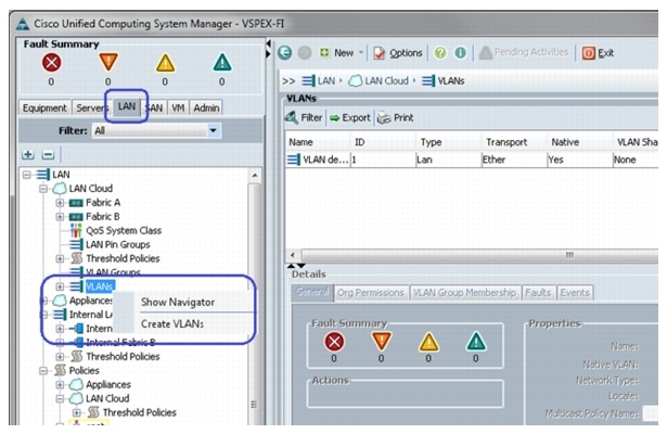
Configure Global VLANs and VSANs
Figure 23 shows how to configure VLAN on a switch.
Figure 23 Creating VLAN
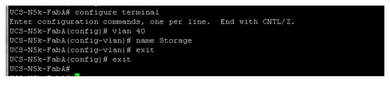
Following VLANs in Table 7 need to be configured on both switches A and B in addition to your application specific VLANs:
For actual VLAN IDs of your deployment, see Customer Configuration Data Sheet.
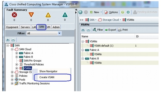
We have used one VSAN in this solution. Table 8 gives the VSAN name and the description.
Table 8 Configured VSAN To Access Storage Array
Storage
VSAN to access storage array from the servers over fibre channel
For actual VSAN ID of your deployment, see Customer Configuration Data Sheet.
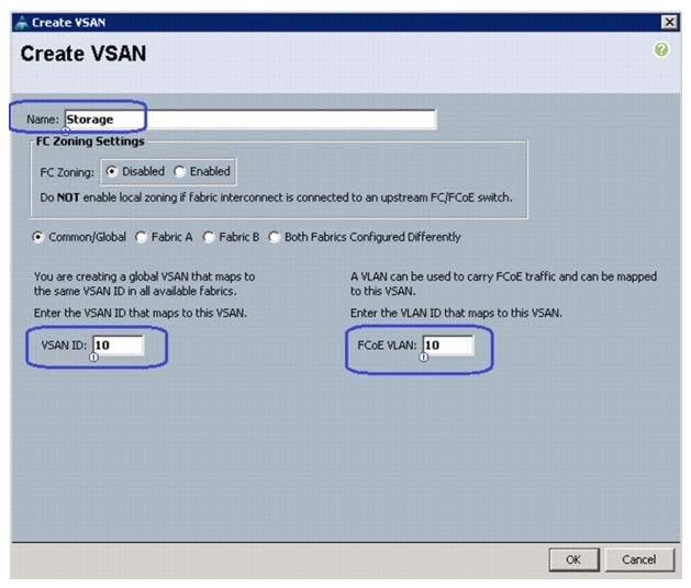
Figure 24 and Figure 25 show the creation of VSAN and assigning VSAN to the fibre channel interface.
Figure 24 Creating VSAN
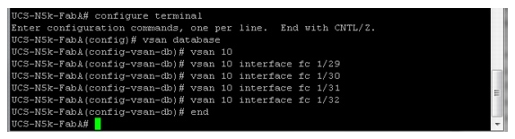
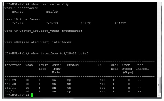
After creating the VSAN. VSAN membership is assigned, and the peer interfaces on the links need to be configured properly, a healthy fibre channel port is shown in Figure 25.
Figure 25 Assigned VSAN Membership
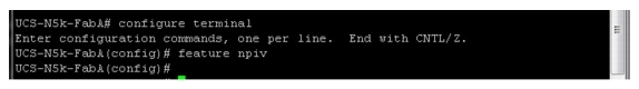
It is also crucial to enable NPIV feature on the Cisco Nexus 5548UP switches. Figure 26 show how to enable NPIV feature on Nexus 5548UP switches.
Figure 26 Enabling Npiv Feature On Cisco Nexus Switches
Configuring Virtual Port Channel (vPC)
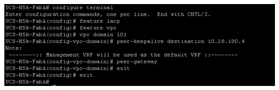
Virtual port-channel effectively enables two physical switches to behave like a single virtual switch, and port-channel can be formed across the two physical switches. Following are the steps to enable vPC:
1.
2.
3.
4.
Figure 27 Configuring Peer-Gateway
5.
Figure 28 Configured VPC Peer-link on Port-Channel
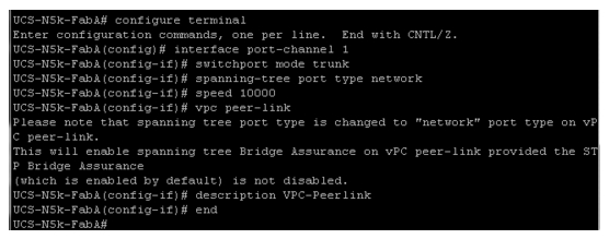
6.
7.
Figure 29 Window Showing Successful vPC Configuration
Configuring Port-Channels Connected to Cisco UCS Fabric Interconnects
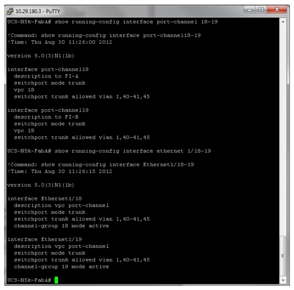
Interfaces connected to the fabric interconnects need to be in the trunk mode. Storage, vMotion, infra, and application VLANs are allowed on this port. From the switch side, interfaces connected to Cisco UCS FI-A and Cisco UCS FI-B are in a vPC, and from the FI side the links connected to Cisco Nexus 5548UP A and B switches are in LACP port-channels. Ensure that you give a right description for each port and port-channel on the switch for better diagnosis in case of any problem. Figure 30 shows the configuration commands.
Figure 30 Port-channel Configuration
Configuring Storage Connectivity
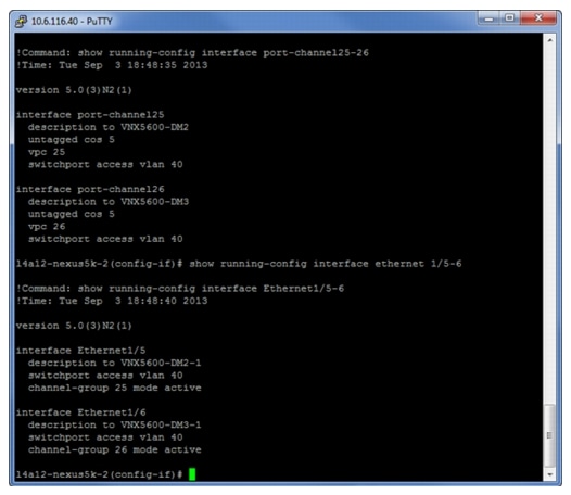
From each switch one link connects to each storage processor on the VNX storage array. A virtual port-channel is created for the two links connected to a single storage processor, but connected to two different switches. In this example configuration, links connected to the storage processor A (SP-A) of VNX storage array are connected to Ethernet port 1/26 on both the switches and links connected to the storage processor B (SP-B) are connected to Ethernet port 1/25 on both the switches. A virtual port-channel (id 26) is created for the Ethernet port 1/26 on both the switches and another virtual port-channel (id 25) is created for the Ethernet port 1/25 on both the switches.

Note
Figure 31 shows the configuration on the port-channels and interfaces.
Figure 31 Configuration of Port-channel and Interfaces
Configuring Ports Connected To Infrastructure Network
Port connected to infrastructure network need to be in trunk mode, and they require at least infrastructure VLAN, N1k control and packet VLANs at the minimum. You may require enabling more VLANs as required by your application domain. For example, Windows virtual machines may need to access to active directory / DNS servers deployed in the infrastructure network. You may also want to enable port-channels and virtual port-channels for high availability of infrastructure network.
Verify VLAN and Port-channel Configuration
At this point of time, all ports and port-channels are configured with necessary VLANs, switchport mode and vPC configuration. Validate this configuration using the "show vlan", "show port-channel summary" and "show vpc" commands as shown in Figure 32.
Note
Figure 32 Validating Created Port-Channels with VLANs
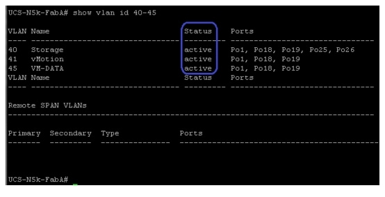
show vlan command can be restricted to a given VLAN or set of VLANs as shown in Figure 32. Ensure that on both switches, all required VLANs are in "active" status and right set of ports and port-channels are part of the necessary VLANs.
Port-channel configuration can be verified using "show port-channel summary" command. Figure 33 shows the expected output of this command.
Figure 33 Verifying Port-Channel Configuration
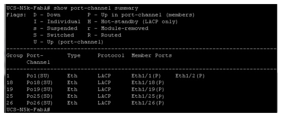
In this example, port-channel 1 is the vPC peer-link port-channel, port-channels 25 and 26 are connected to the storage arrays and port-channels 18 and 19 are connected to the Cisco UCS FI A and B. Make sure that the state of the member ports of each port-channel is "P" (Up in port-channel).
Note
Common reasons for port-channel port being down are:
•
•
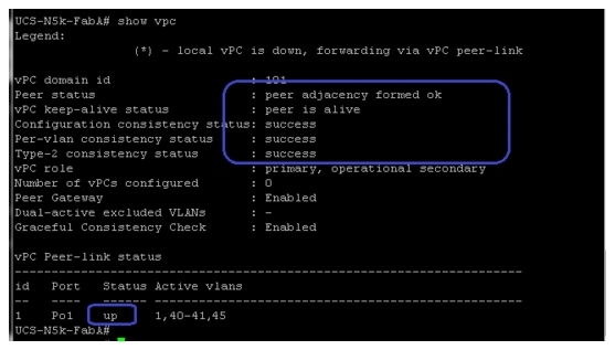
vPC status can be verified using "show vpc" command. Example output is shown in Figure 34.
Figure 34 Verifying VPC Status
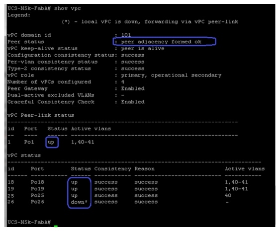
Ensure that the vPC peer status is "peer adjacency formed ok" and all the port-channels, including the peer-link port-channel status are "up", except one of the two port-channels connected to the storage array as explained before.
Configuring QoS
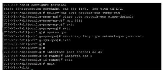
The Cisco solution for the EMC VSPEX VMware architectures require MTU to be set at 9216 (jumbo frames) for efficient storage and vMotion traffic. MTU configuration on Cisco Nexus 5000 fall under global QoS configuration. You may need to configure additional QoS parameters as needed by the applications. For more information on the QoS configuration, see Cisco Nexus 5000 Series Configuration Guide.
To configure jumbo MTU on the Cisco Nexus 5000 series switches, follow these steps on both switch A and B:
1.
2.
3.
4.
Figure 35 shows the exact Cisco Nexus CLI for the steps mentioned above.
Figure 35 Configuring MTU on Cisco Nexus Switches
Note
Prepare UCS FIs and configure UCS Manager
Configure UCS FIs and UCS Manager can be subdivided in to following segments:
1.
2.
3.
5.
6.
7.
Following subsections provided details on each of the steps mentioned above.
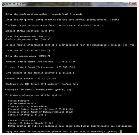
Initial Configuration of Cisco UCS FIs
At this point of time, the Cisco UCS FIs, FEX, and Blade Servers or Rack Servers must be mounted on the rack and appropriate cables must be connected. Two 100 Mbps Ethernet cables must be connected between two FIs for management pairing. Two redundant power supplies are provided per FI, it is highly recommended that both the power supplies are plugged in, ideally drawing power from two different power strips. Connect mgmt0 interfaces of each FI to the infrastructure network, and put the switch port connected to FI in access mode with access VLAN as management VLAN.
To perform initial FI configuration, follow these steps:
1.
Figure 36 Initial Configurations of Cisco UCS Fabric Interconnect
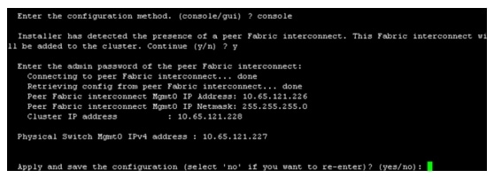
2.
Figure 37 Configuring Peer a Fabric Interconnect
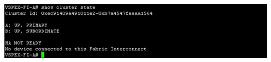
3.
Figure 38 Cisco UCS Fabric Interconnect - Cluster State
Configuration for Server Discovery
All the Ethernet ports of FIs are unconfigured and shutdown by default. You need to classify these ports as server facing ports, directly attached storage array facing ports, and uplink ports.
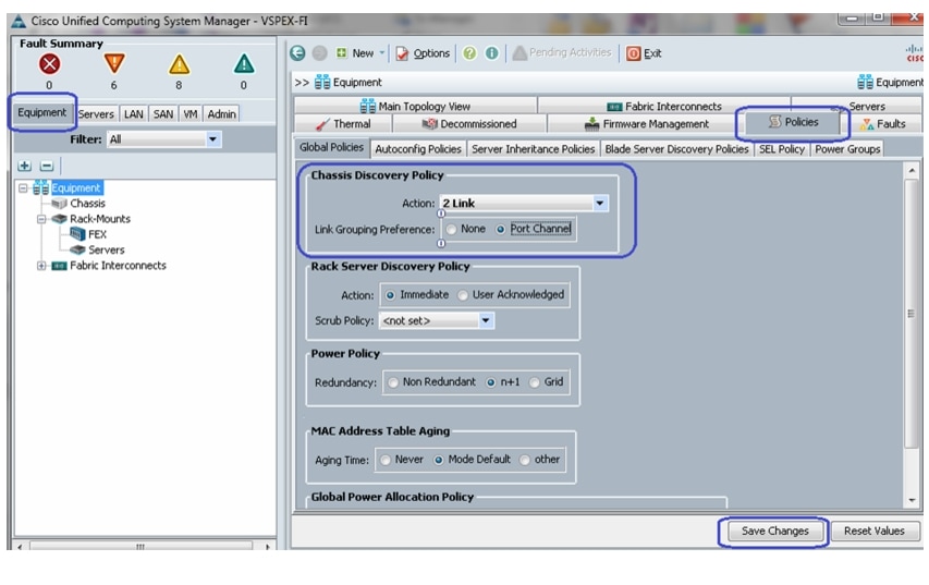
To configure the ports for proper server auto-discovery, follow these steps:
1.
Figure 39 Configuring Chassis Discovery Policy
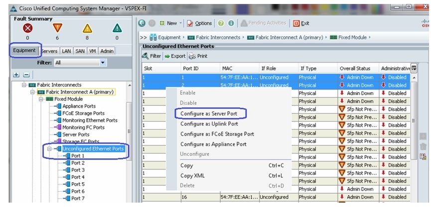
2.
Figure 40 Configuring Ethernet Ports as Server Ports
3.
4.
Figure 41 Overall Status of FEX After Auto-Discovery
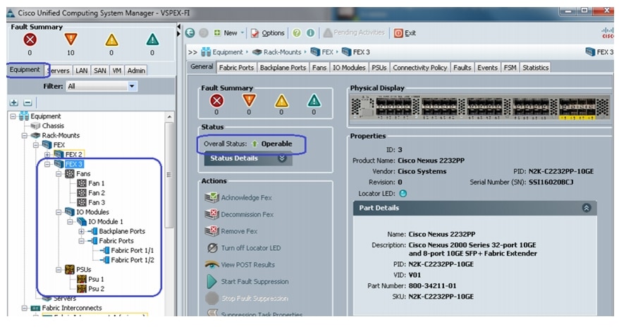
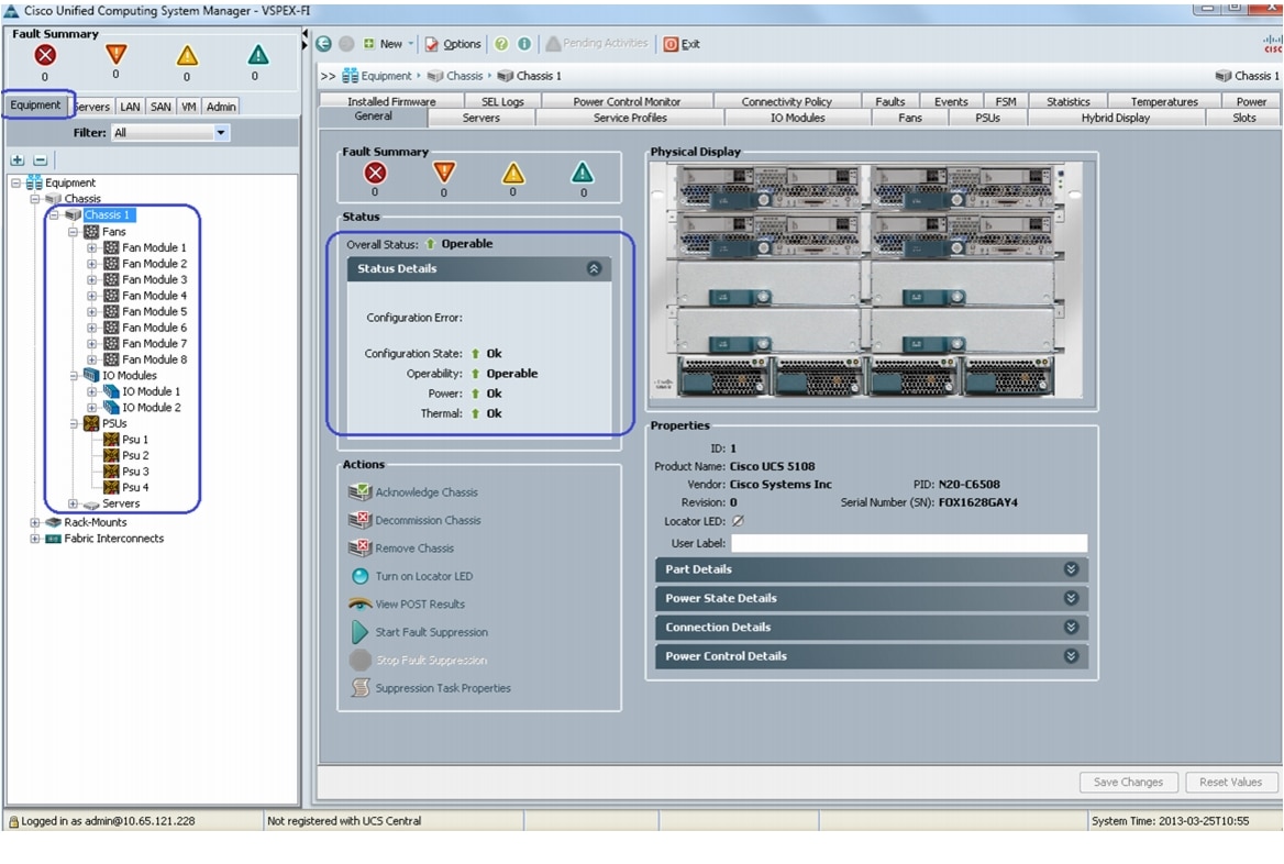
Similarly, if server ports are connected to the chassis, you will see that the chassis is fully discovered, with all its IOMs, fans, power supplies and so on.
Figure 42 Overall Status of Chassis After Auto-Discovery
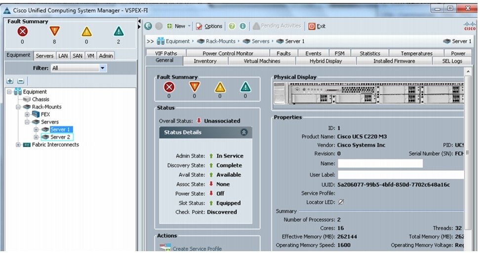
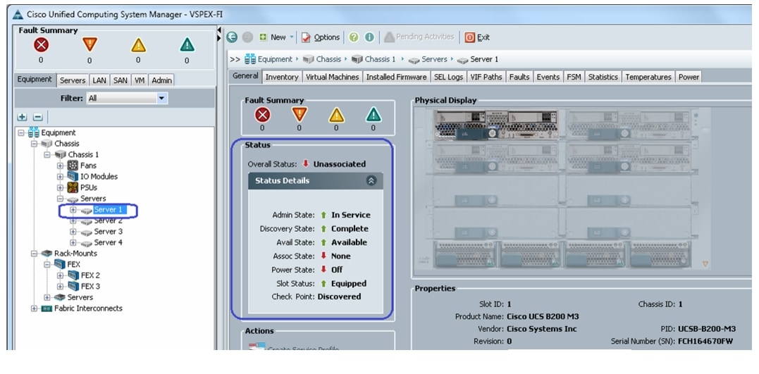
5.
Figure 43 Overall Status of Rack Servers After Discovery
Similarly, a Blade Server's status is shown in Figure 44.
Figure 44 Overall Status of Blade Servers After Discovery
6.
Figure 45 Summary of Rack Servers After the Discovery
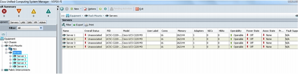
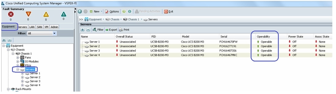
Or, in case of Blade Servers, you can see the summary by choosing Equipment tab > Chassis > Chassis <id> > Servers.
Figure 46 Summary of Blade Servers After the Discovery
Upstream/ Global Network Configuration
This subsection lists a few upstream/ global network configuration:
1.
2.
3.
4.
5.
6.
7.
8.
9.
10.
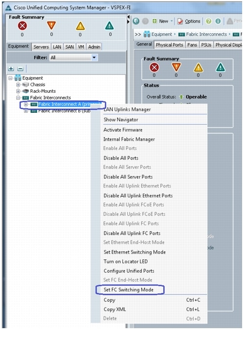
To configure upstream/ global network, follow these steps:
1.
Figure 47 Setting FC Switching Mode on Fabric A for FC-Variant
2.
3.
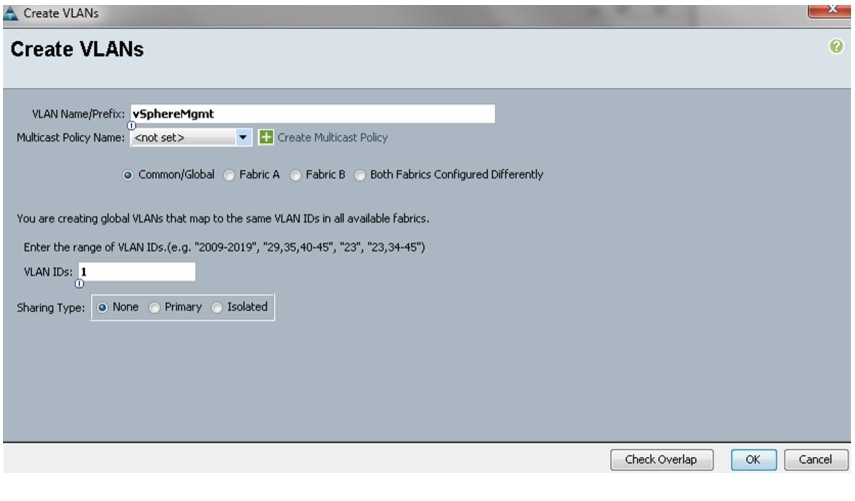
Figure 48 Creating VLANs
4.
Figure 49 VLAN Details for Creating VLAN
5.
6.
Figure 50 Creating VSAN for NFS-Variant
7.
Figure 51 VSAN Details for Creating VSAN
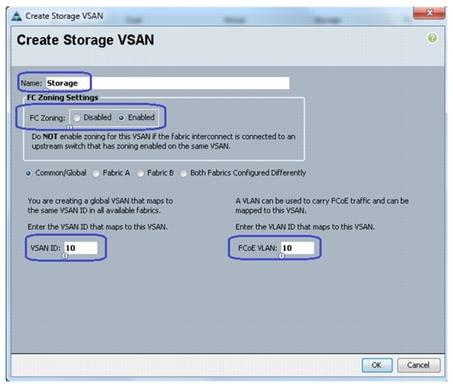
8.
Figure 52 Creating Storage VSAN for FC-Variant
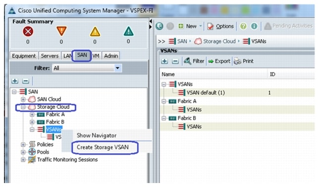
9.
Figure 53 VSAN Details for Creating Storage VSAN
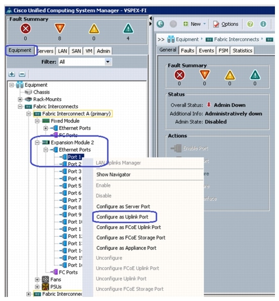
10.
Figure 54 Configuring Ethernet Ports as Uplink Ports
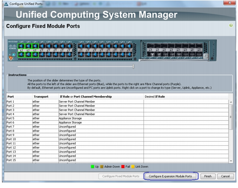
11.
Figure 55 Configuring Ethernet Ports as FC Ports for Storage Connectivity
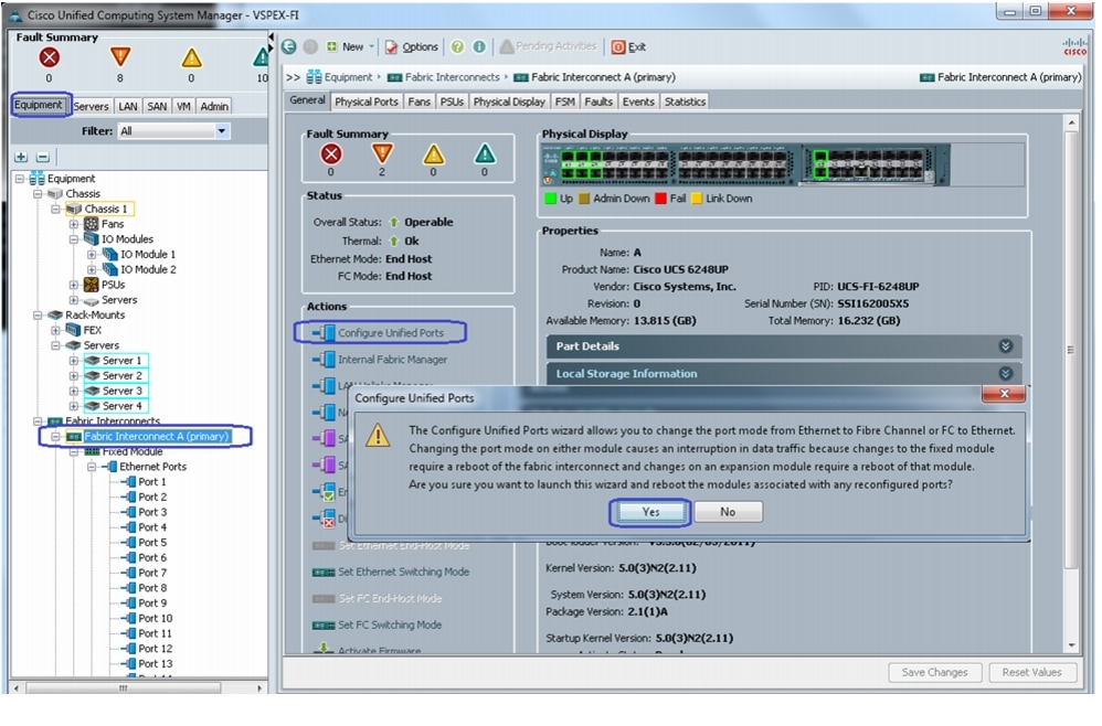
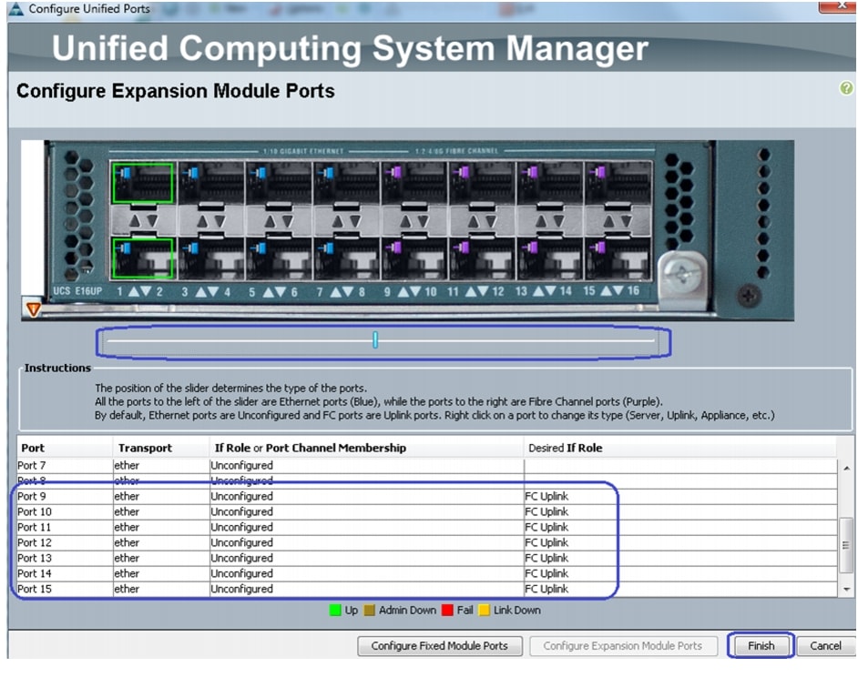
12.
Figure 56 Configuring Expansion Module Ports
13.
Figure 57 Verifying FC Upink on Ports 9 to 15
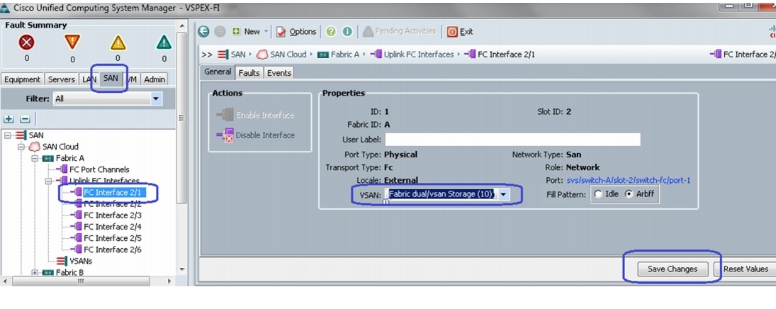
14.
15.
Figure 58 Selecting Storage VSAN for NFS-Variant
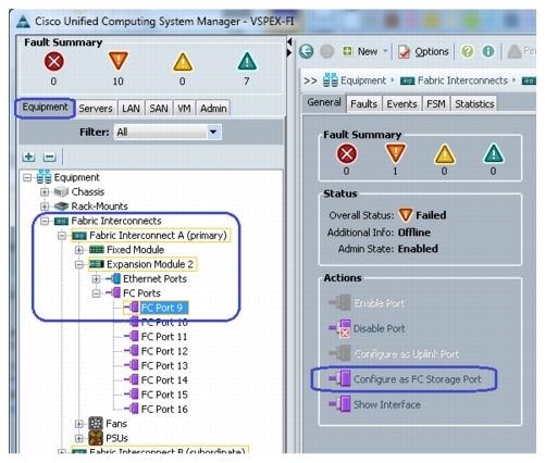
16.
Figure 59 Configuring FC Port as FC Storage Port for FC-Variant
17.
Figure 60 Selecting Storage VSAN for FC-Variant
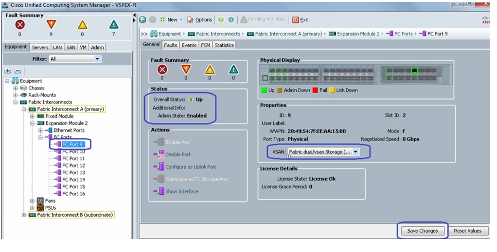
18.
Figure 61 Port Name (WWPN) of the Storage Array
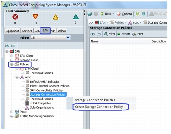
19.
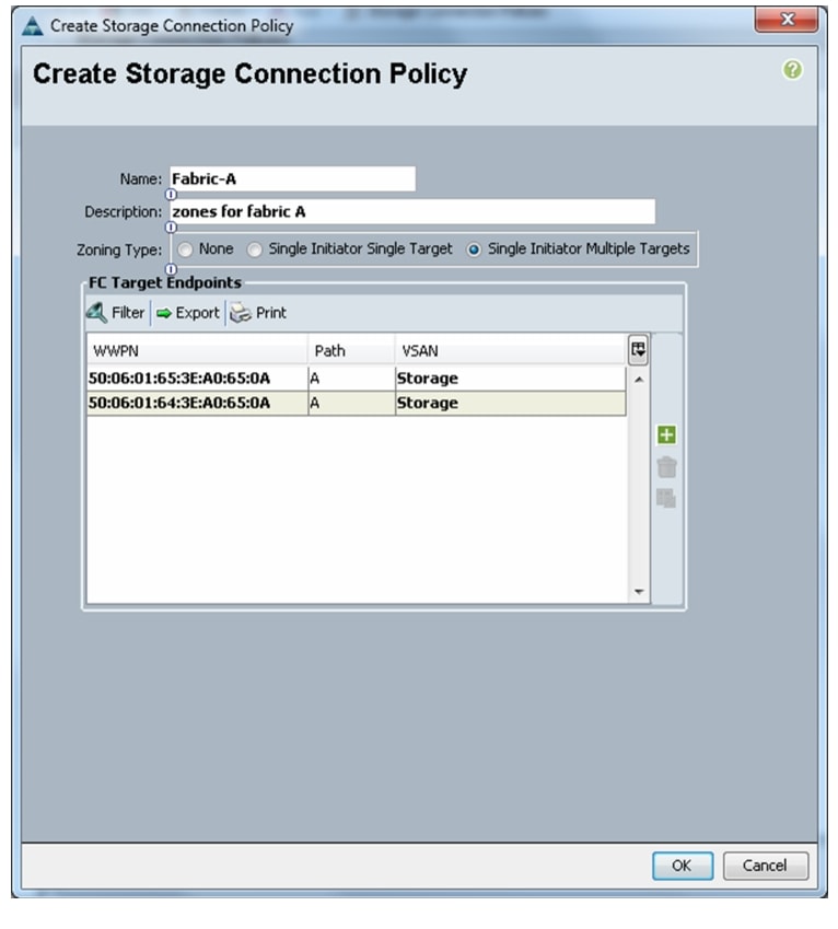
Figure 62 Creating Storage Connection Policy
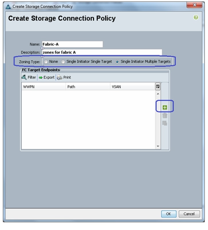
20.
to add a new FC Target Endpoint.
Figure 63 Details for Creating Storage Connection Policy for FC-Variant
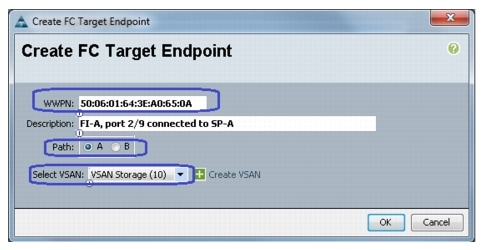
21.
Figure 64 Creating FC Target Endpoint for Fabric A
22.
Figure 65 Adding Second FC Target Endpoint for Fabric A
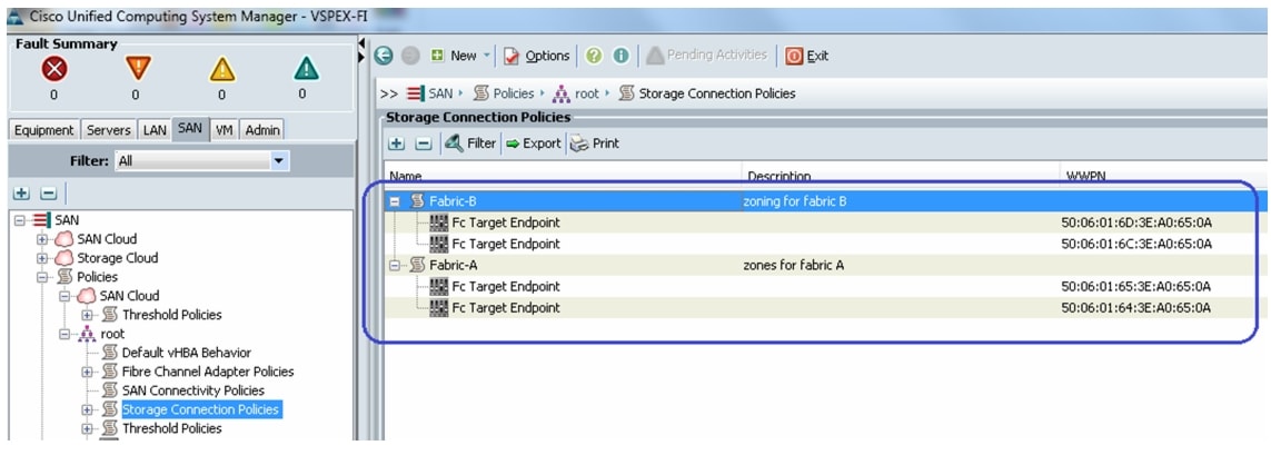
23.
Figure 66 FC Target Endpoints on Fabric A and Fabric B
24.
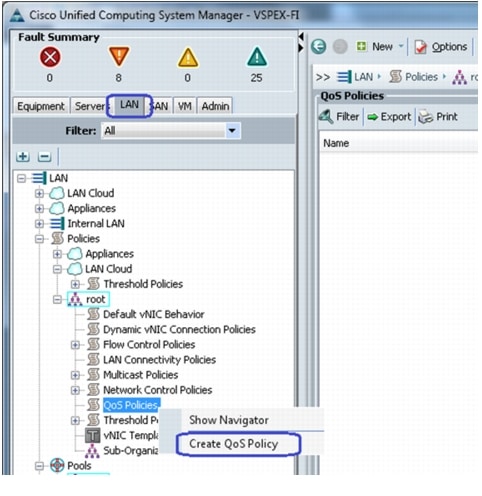
Figure 67 Configuring QoS
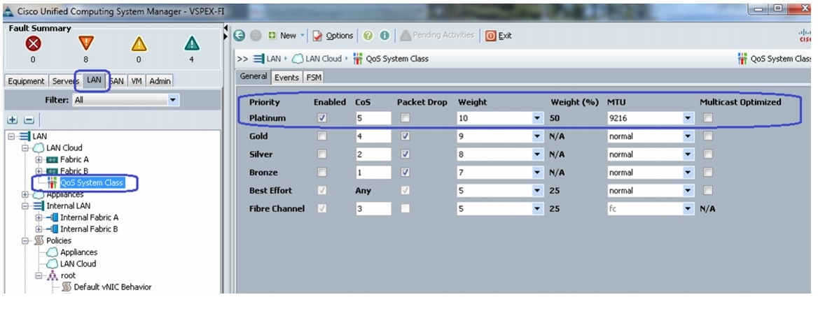
25.
Figure 68 Creating QoS Policy
26.
Configure Identifier Pools
In this section, we would configure following identifier pools used by service profile:
1.
2.
3.
4.
To configure pools mentioned above, follow these steps:
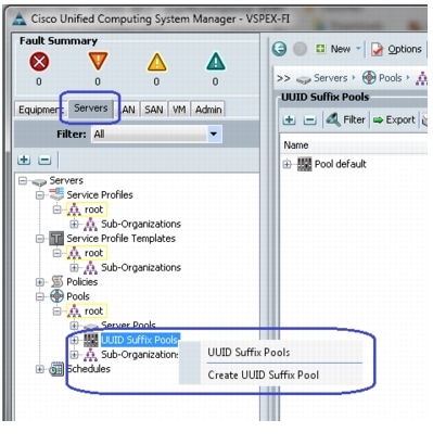
1.
Figure 69 Creating UUID Suffix Pool
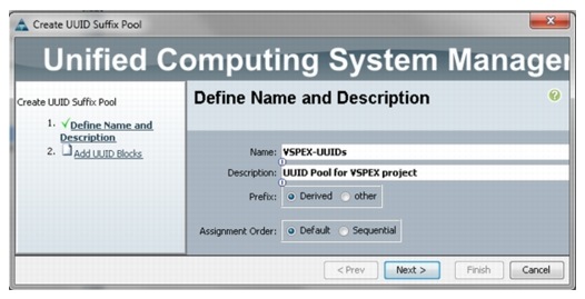
2.
Figure 70 Details for Creating UUID Suffix Pool
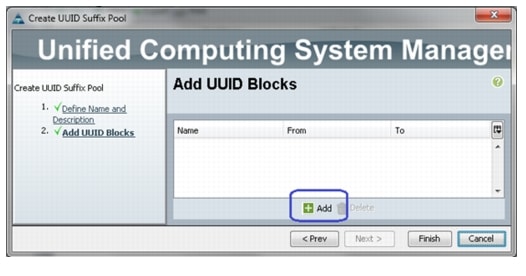
3.
add UUID block.
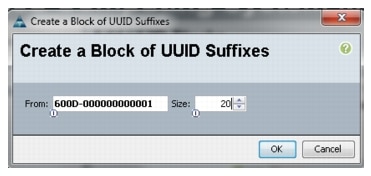
Figure 71 Adding UUID Block
4.
Figure 72 Specifying Block Size
5.
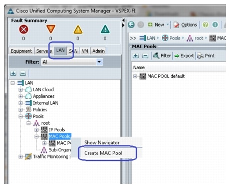
6.
Figure 73 Creating MAC Pool

7.
Figure 74 Details for Creating MAC Pool
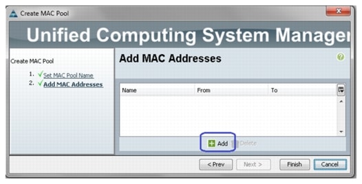
8.
to add MAC pool block.
Figure 75 Adding MAC Address
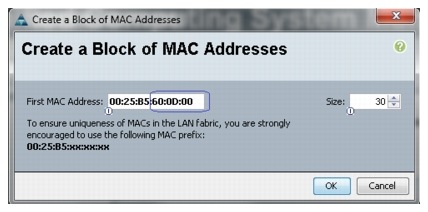
9.
Figure 76 Specifying MAC Address Block
10.
11.
Figure 77 Creating WWxN Pool
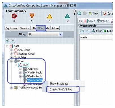
12.
13.
to add a block of WWxN IDs.
Figure 78 Adding WWxN Block
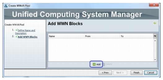
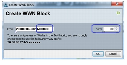
14.
Figure 79 Specifying WWxN Block Size
15.
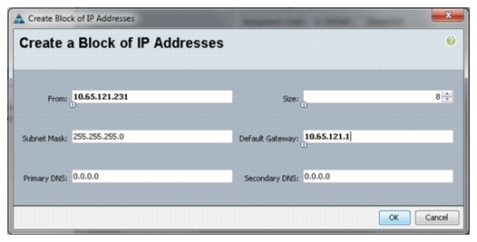
Figure 80 Creating IP Address Block
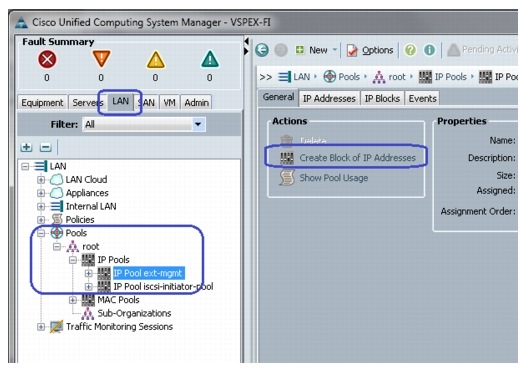
16.
Figure 81 Specifying the IP address Block Size
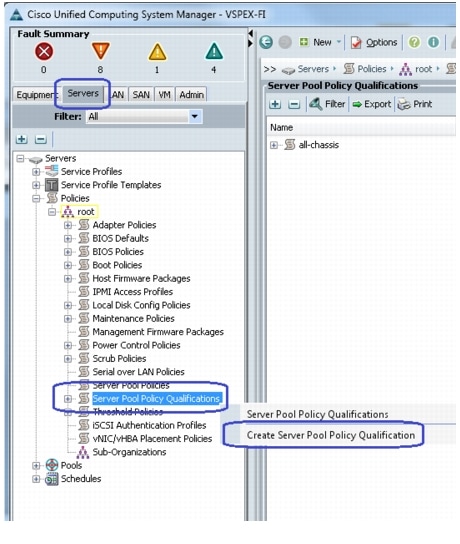
Configure Server Pool and Qualifying Policy
Creation and policy based auto-population of server pool can be sub-divided into the following tasks:
1.
2.
3.
Follow these steps to complete the three tasks mentioned above:
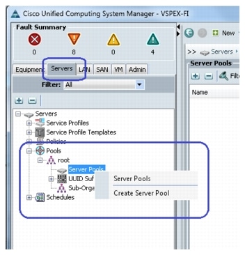
1.
Figure 82 Creating Server Pools
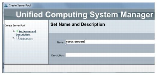
2.
Figure 83 Entering Details in the Create Server Pool Wizard
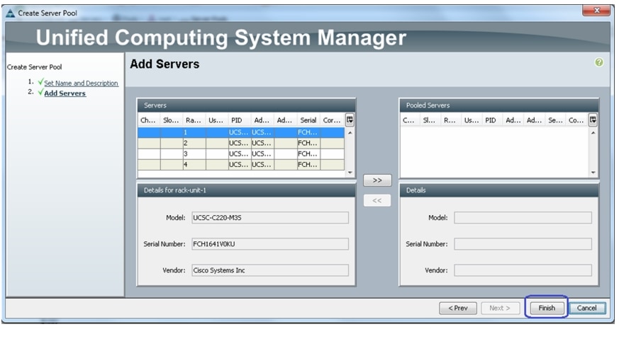
3.
Figure 84 Adding Servers in the Create Server Pool Wizard
4.
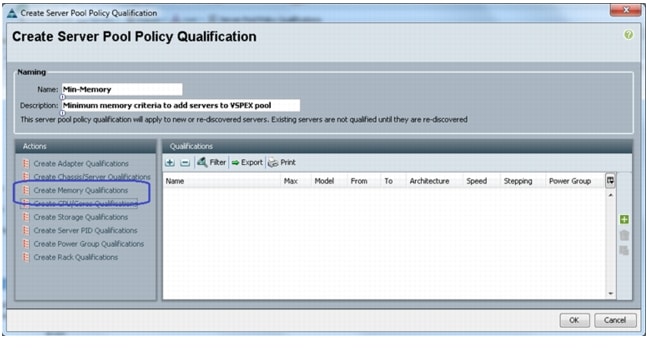
Figure 85 Creating Server Pool Policy Qualification
5.
Figure 86 Creating Memory Qualification
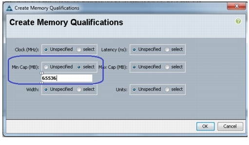
6.
Note
Figure 87 Specifying Minimum RAM Capacity for Memory Qualification
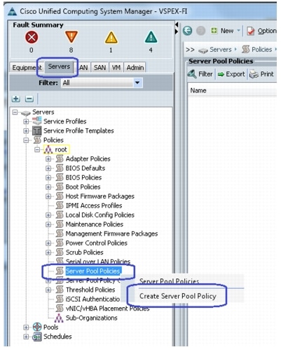
7.
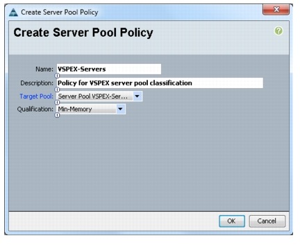
Figure 88 Creating Server Pool Policy
8.
Figure 89 Details for Creating Server Pool Policy
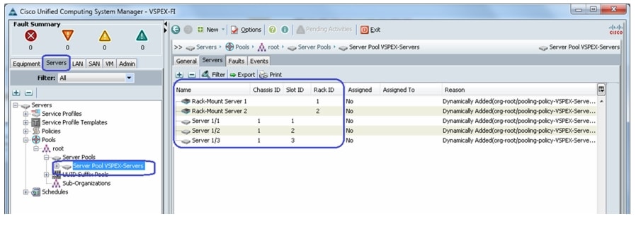
9.
Figure 90 Qualified Compute Resources Automatically Added to the Server Pool
Configure Service Profile Template
At this point, we are ready to create service profile template, from which we can instantiate individual service profiles later.
To create service profile template, follow these steps:
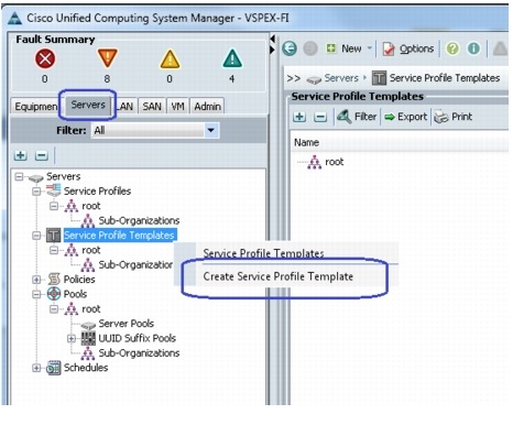
1.
Figure 91 Creating Service Profile Template
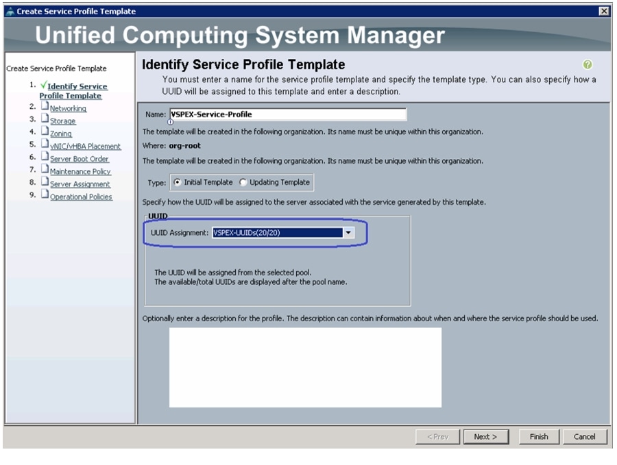
2.
Figure 92 Creating Service Profile Template - Entering Details
3.
Figure 93 Creating Service Profile Template - LAN Configuration Details
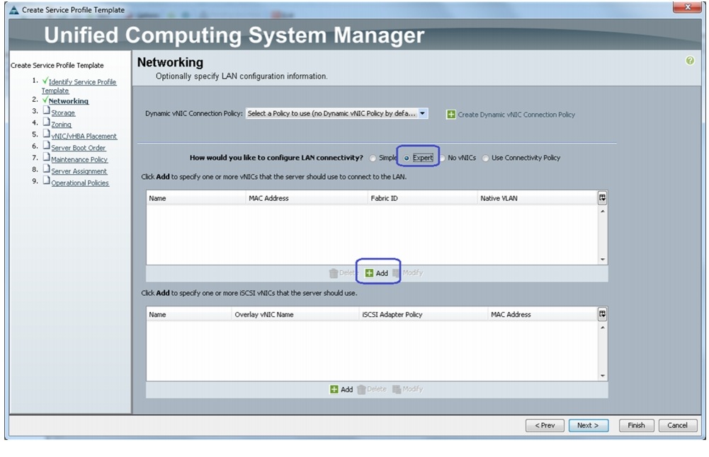
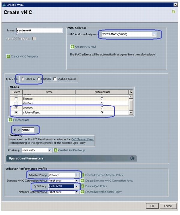
4.
Figure 94 Creating a System vNIC
5.
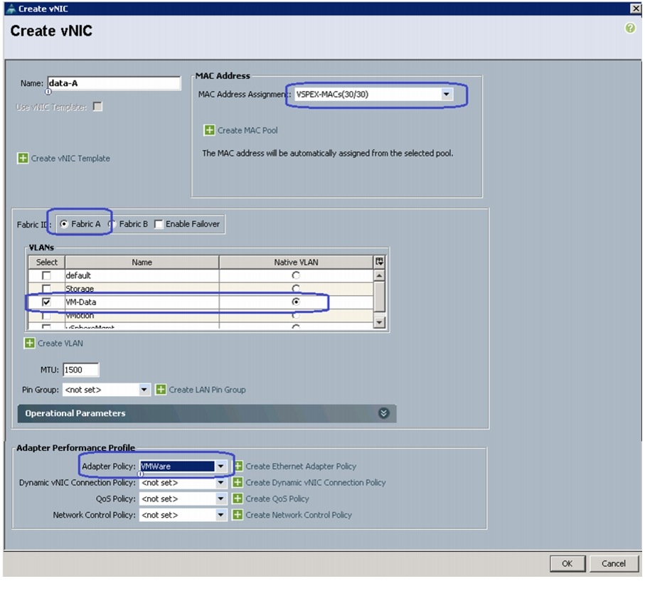
6.
7.
Figure 95 Creating vNIC for VM Data Traffic
8.
*Storage vNICs are created for NFS-variant only9.
Figure 96 Creating Service Profile Template - Storage Configuration Details
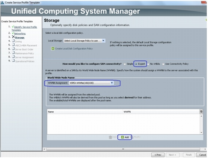
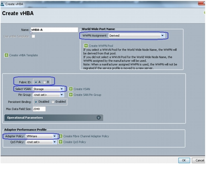
10.
Figure 97 Creating vHBA on Fabric A
11.
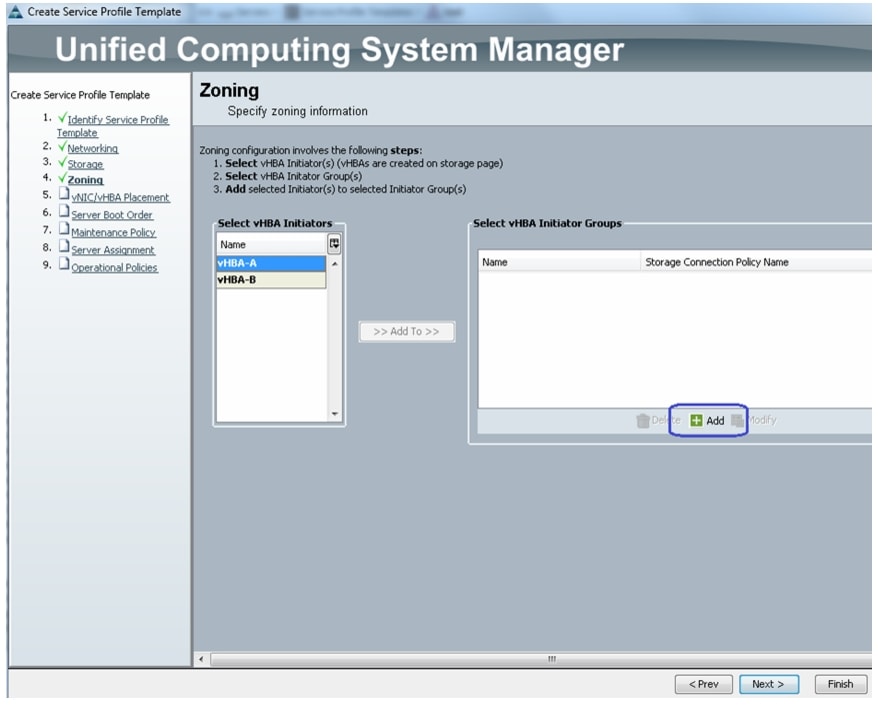
12.
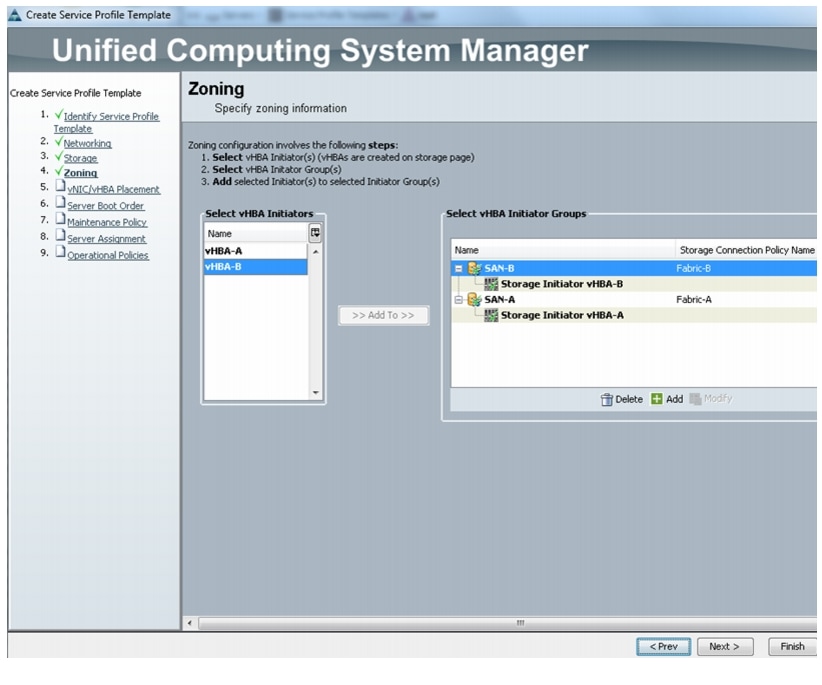
Figure 98 Creating Service Profile Template - Zoning Details
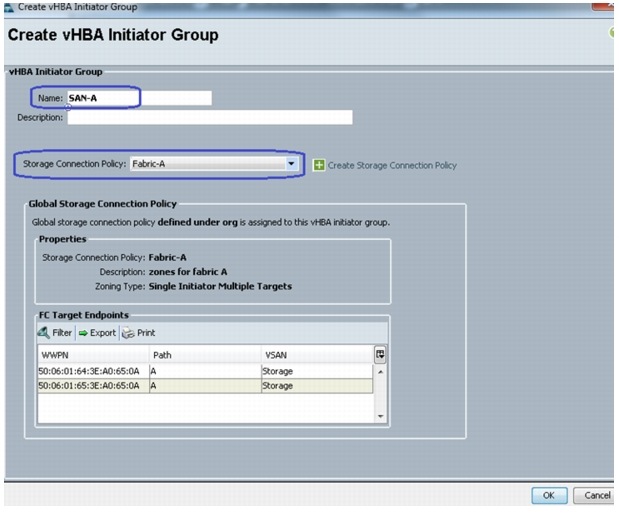
13.
Figure 99 Creating vHBA Initiator Group for FC-Variant
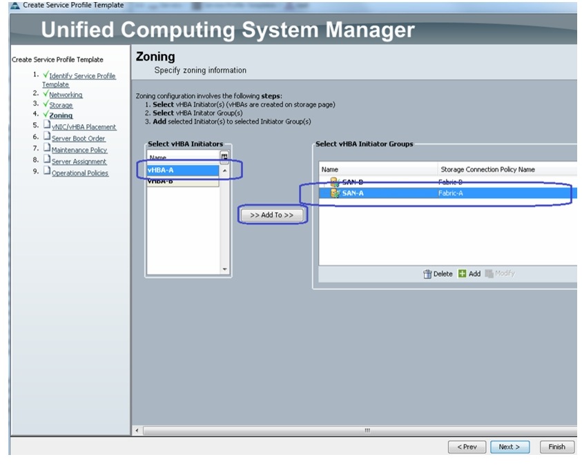
14.
Figure 100 Adding vHBA to vHBA Initiator Group
15.
Figure 101 Window Showing vHBAs Added to the Initiator Group
16.
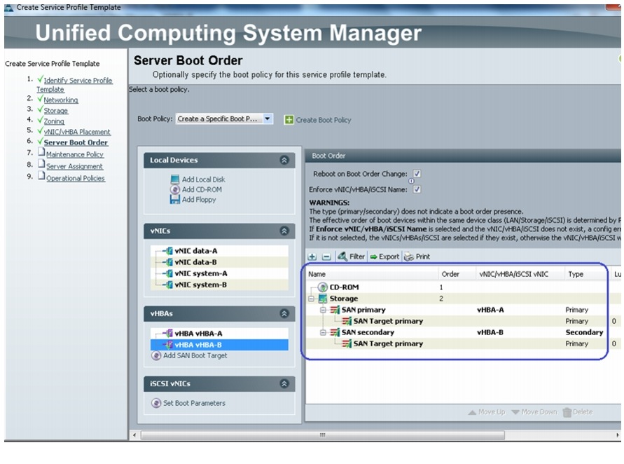
17.
Figure 102 Creating Service Profile Template - Configuring Boot Order
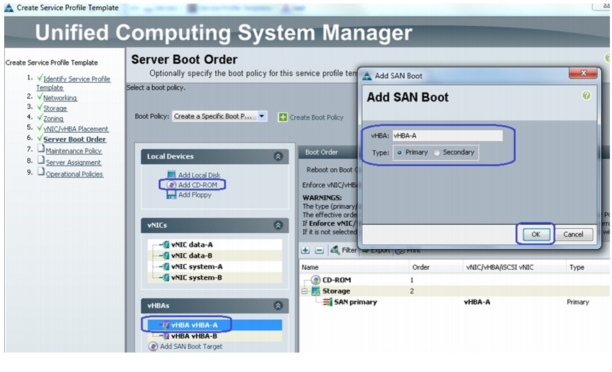
18.
Figure 103 Adding SAN Boot Target to SAN Primary
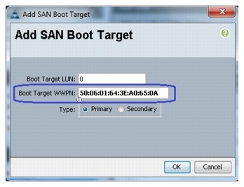
19.
Figure 104 Adding SAN Boot Target as Primary
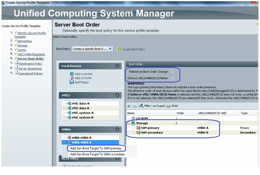
20.
Figure 105 Server Boot Order After the Configuration is Complete
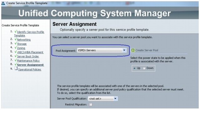
21.
Figure 106 Creating Service Profile Template - Configuring Server Assignment
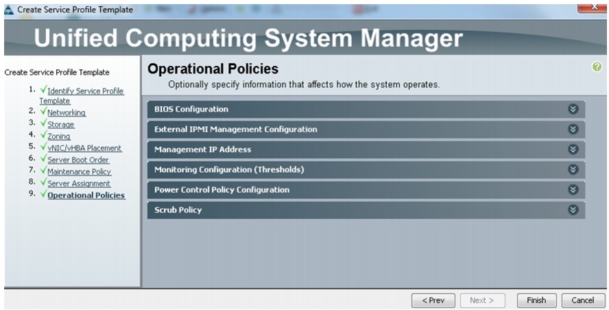
22.
Figure 107 Creating Service Profile Template - Restore Default Settings for Operational Policy
Instantiate Service Profiles from the Service Profile Template
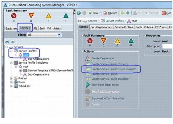
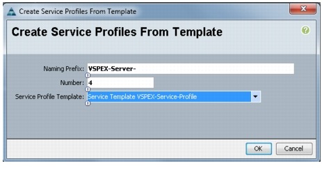
As a final step to configure UCS Manager, we need to instantiate service profiles from the service profile template created in "Configure Service Profile Template" section. Follow these steps to instantiate service profiles from the service profile template:
1.
Figure 108 Creating Service Profile from Template
2.
Figure 109 Details for Creating Service Profiles
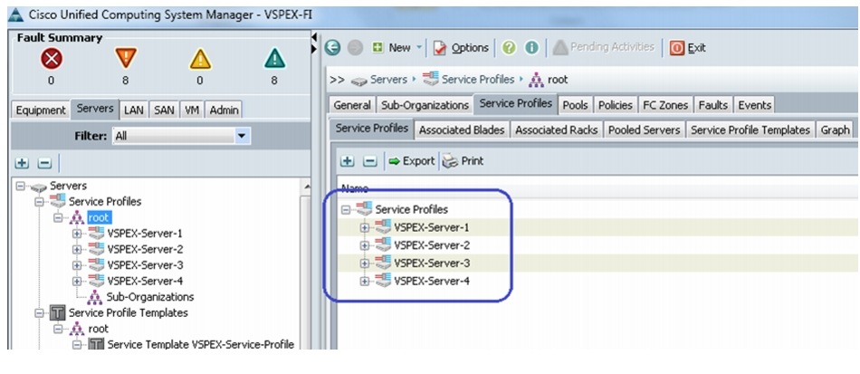
3.
Figure 110 Window Showing All the Service Profiles Created from the Template
4.
Figure 111 Status Details Of Service Profiles
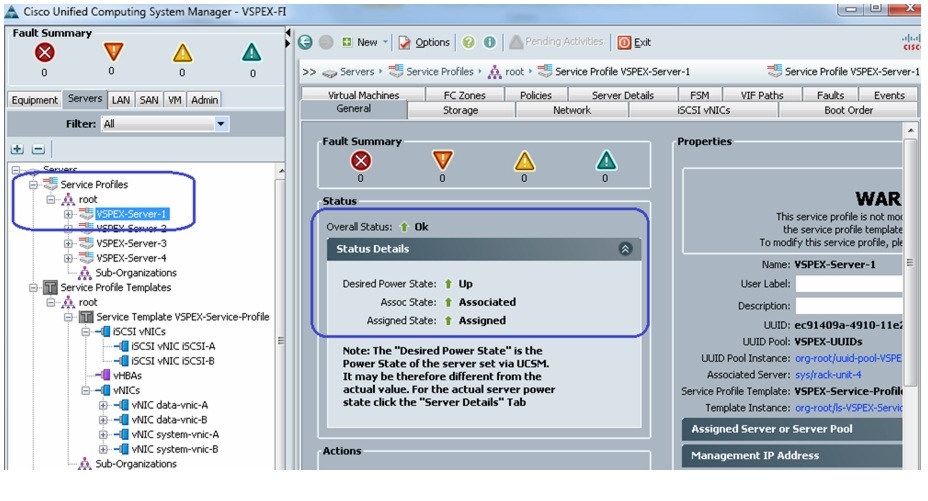
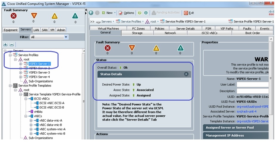
5.
Figure 112 Summary of Service Profiles Showing Assigned State as Associated
Note
Configure Data-Stores for ESXi images
This section provides necessary steps to create FC accessible data-stores for the ESXi boot image per server basis. This can be done in three steps:
Configure Storage Pool
To create storage pool and carve boot LUNs per server basis, follow these steps:
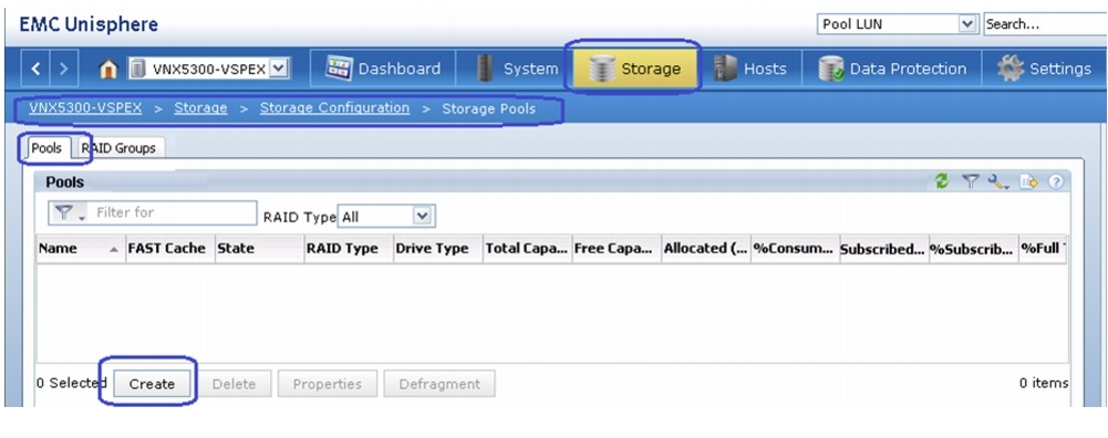
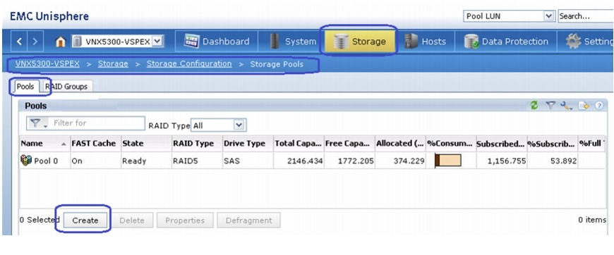
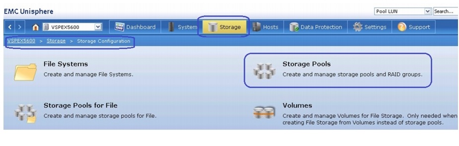
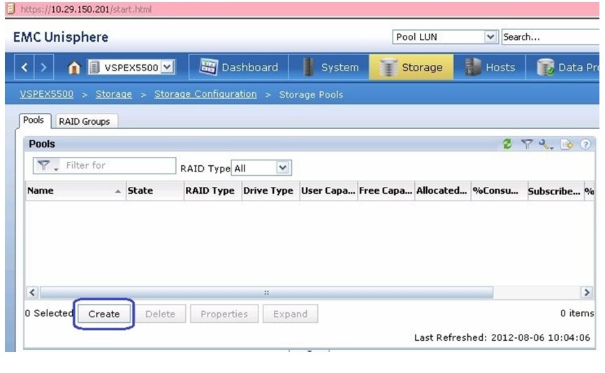
1.
Figure 113 Creating Storage Pools in EMC Unisphere
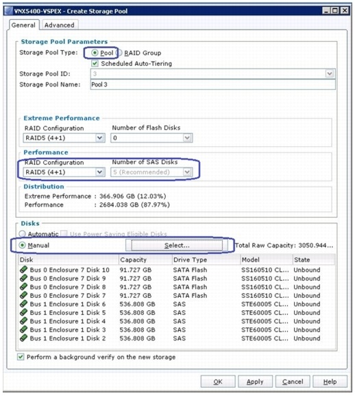
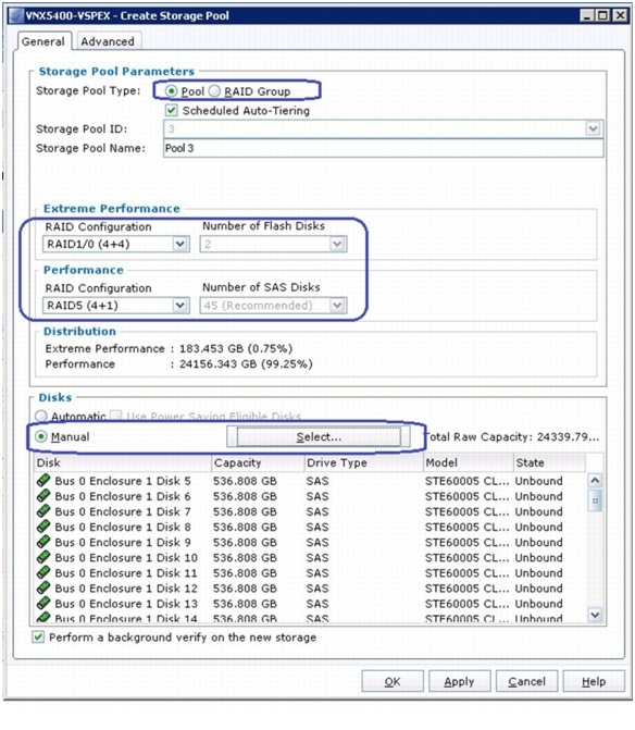
2.
Figure 114 Details for Creating Storage Pools
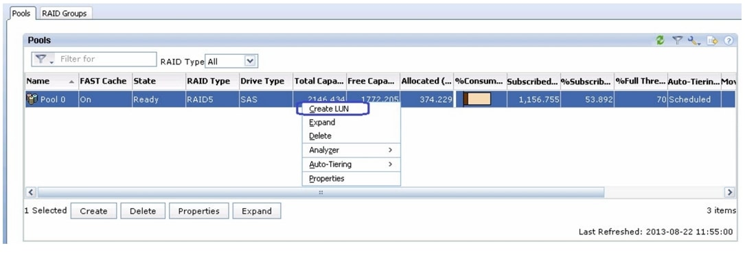
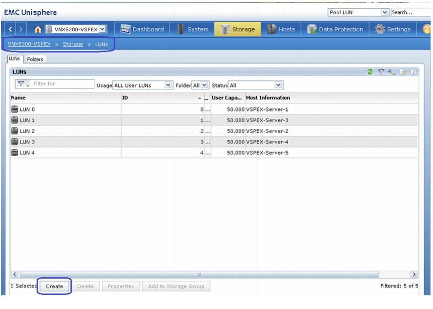
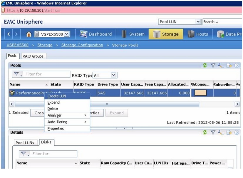
3.
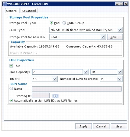
Figure 115 Creating LUN from Created RAID Group
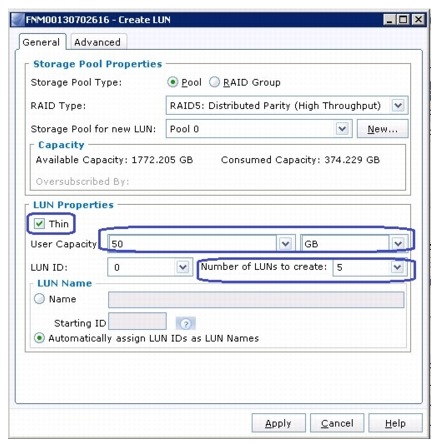
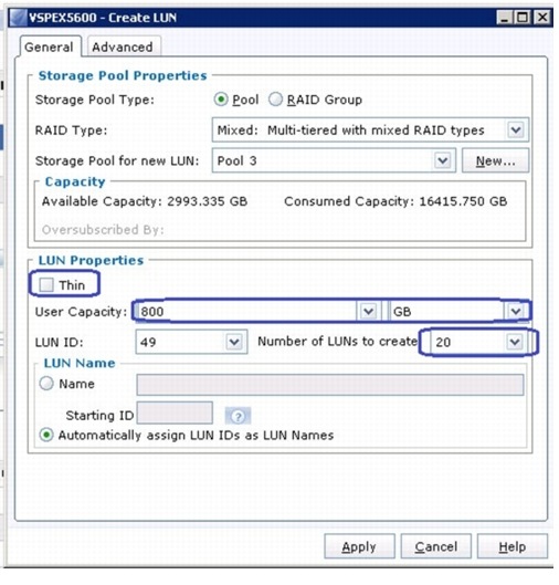
4.
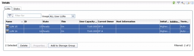
Figure 116 Details for Creating LUN
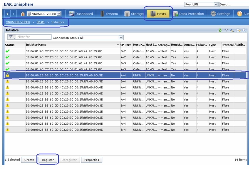
Register Hosts
After the service profiles are associated in UCS Manager, the vHBAs will do flogi in the network and the SAN initiators will be identified by the VNX storage array. To register the hosts identified by the WWPN of the server, follow these steps:
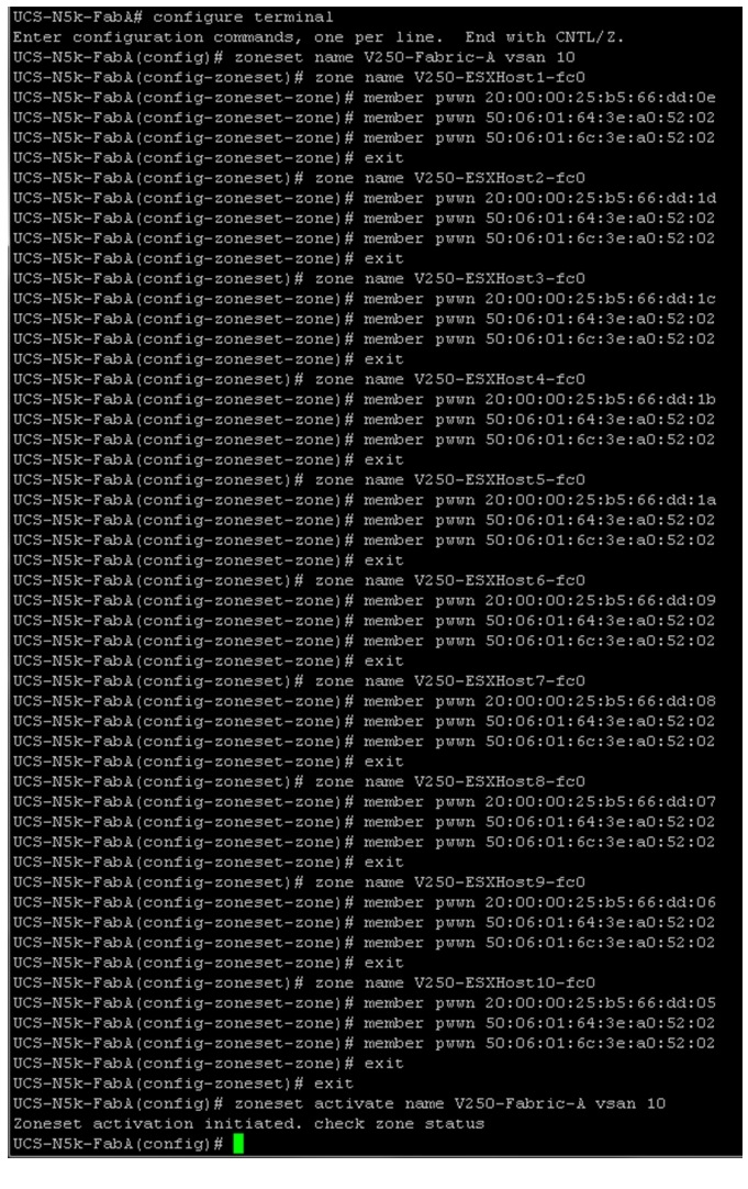
(NFS-variant only) For NFS-variant of the solution, the storage connectivity is through Nexus 5000 switches. In that case, the FC zoning must be configured manually on Nexus 5548UP switches. In contrast to this, in case of FC-variant architecture, where storage is attached to FIs, FC zoning is taken care by UCS Manager implicitly.
To configure zoning on Nexus 5548 UP switches, follow these steps:
1.
Figure 117 Zoneset Configuration on Cisco Nexus 5548UP Switch
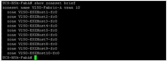
2.
Figure 118 Running show zoneset brief Command for Fabric A
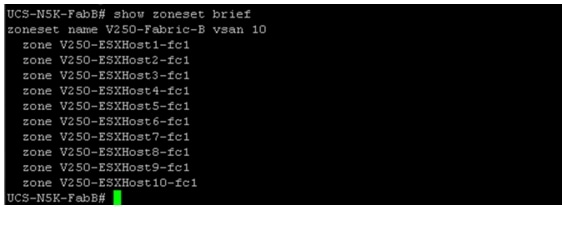
3.
Figure 119 Running show zoneset brief Command for Fabric B
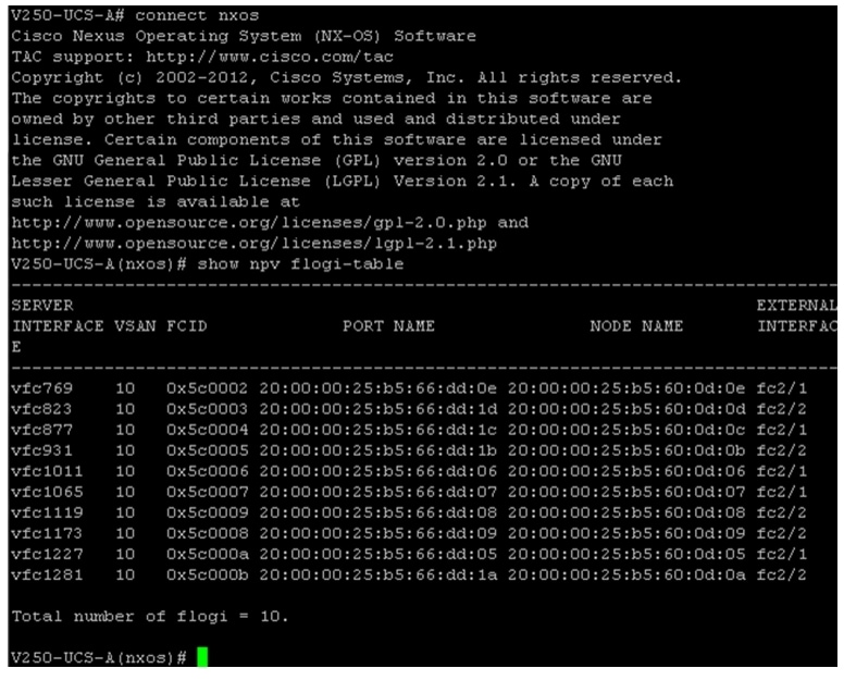
4.
Figure 120 Running show nvp flogi-table to List All the FLogI Sessions
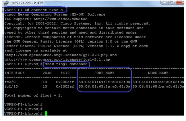
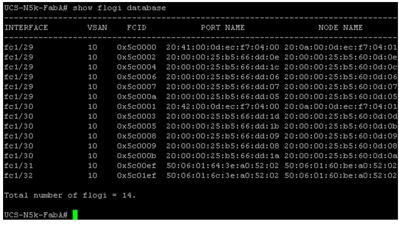
5.
Figure 121 Running show flogi database Command on Cisco Nexus 5548UP
6.
Figure 122 Registering Unregistered Initiator in the EMC Unisphere
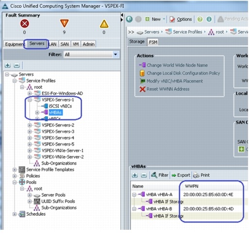
7.
Figure 123 WWPN Identities of vHBAs in Cisco UCS Manager GUI
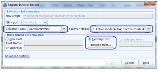
8.
Figure 124 Registering Initiator Record - Part 1
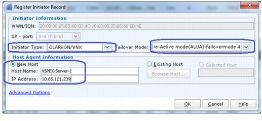
9.
Figure 125 Registering Initiator Record - Part 2
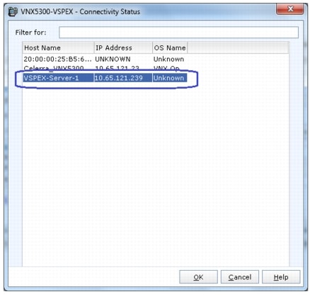
10.
Figure 126 Choosing Registered Host for EMC VNX Connectivity
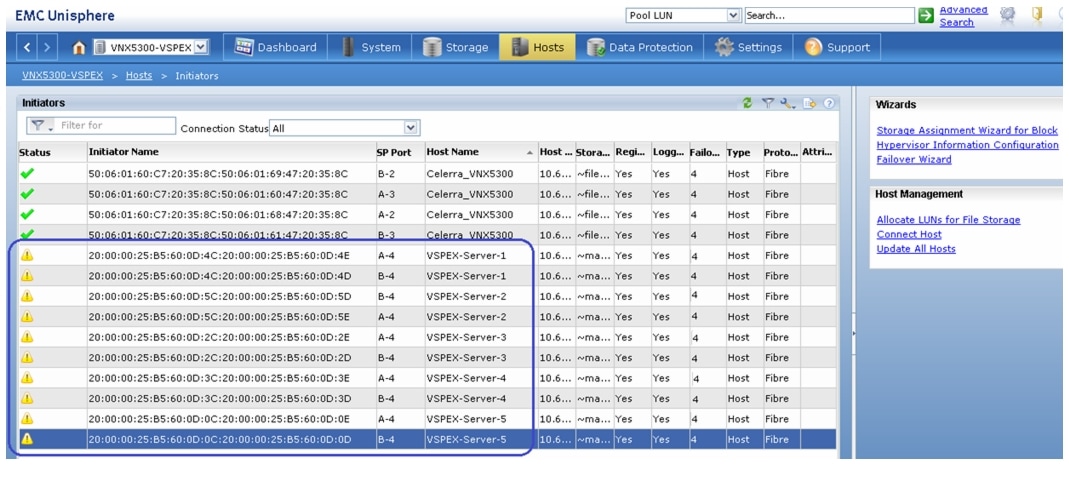
11.
Figure 127 Initiator Window Showing All the Hosts with Initiator Names
Configure Storage Groups
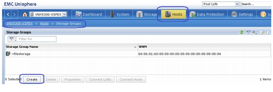
At this point, hosts as well as the LUNs are created on the VNX storage array, we need to create storage groups to assign access to LUNs for various hosts. A Boot LUN will be dedicated to a specific server. Follow these steps to configure storage groups:
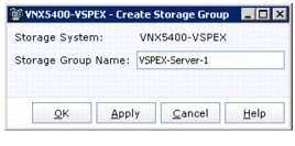
1.
Figure 128 Creating a Storage Group
2.
Figure 129 Name the Storage Group
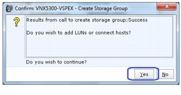
3.
Figure 130 Successful Completion of Storage group Creation
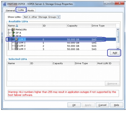
4.
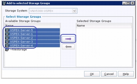
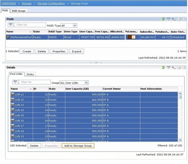
Figure 131 Adding LUNs to the Storage Group
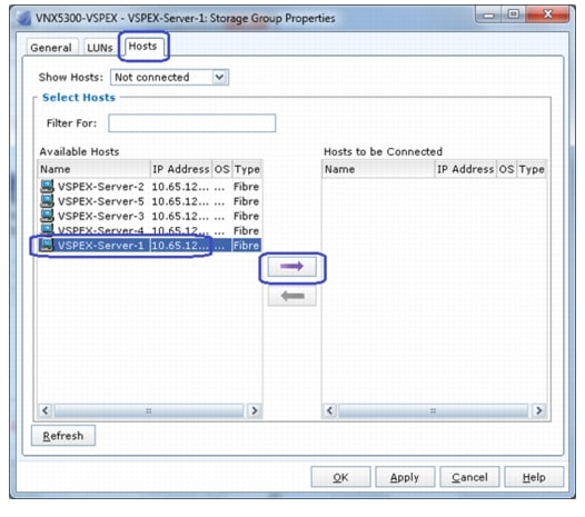
5.
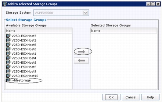
Figure 132 Adding Host to the Storage Group
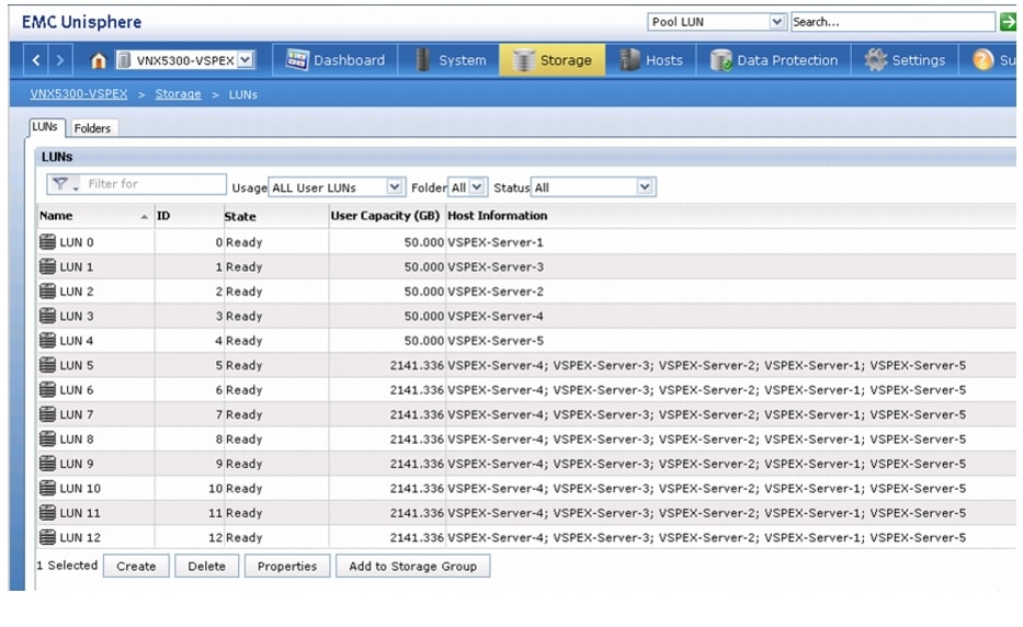
6.Repeat these steps for all the five servers. The end result looks like Figure 133.
Figure 133 Storage Group Showing All the Servers Added
Now, we have end-to-end FC storage access from servers in UCS to the specific boot LUN on the VNX storage devices. We are ready to install ESXi images on the server.
Install ESXi Servers and vCenter Infrastructure
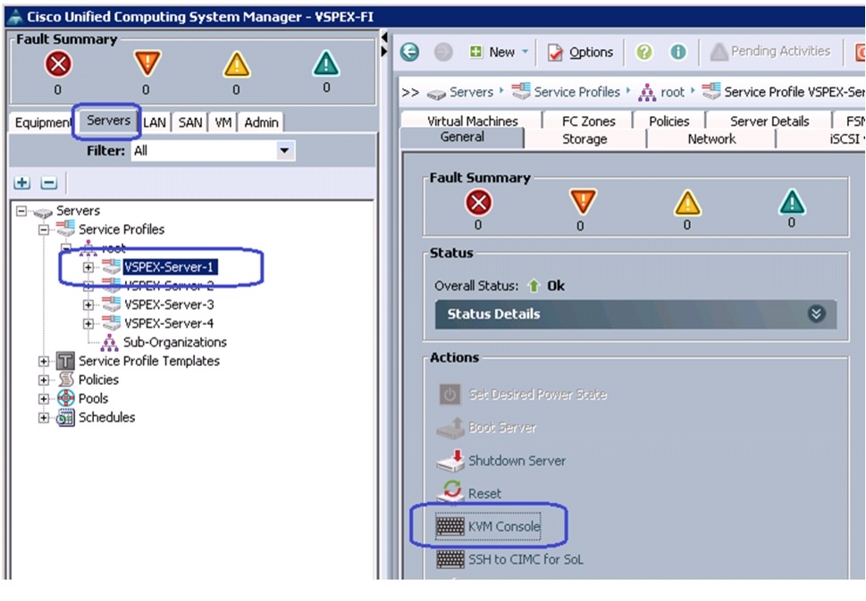
Follow these steps to install ESXi image on Cisco UCS servers:
1.
Figure 134 Launching KVM Console
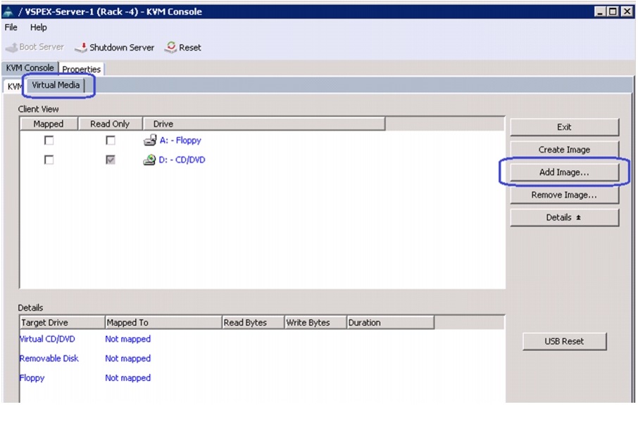
2.
Figure 135 Adding an ISO Image of the ESXi 5.1 Hypervisor Installer Media
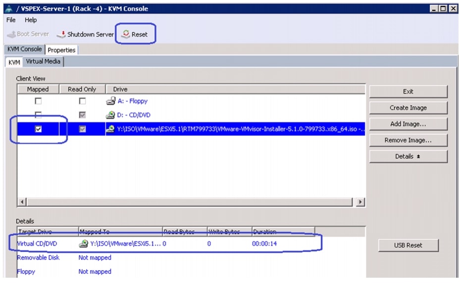
3.
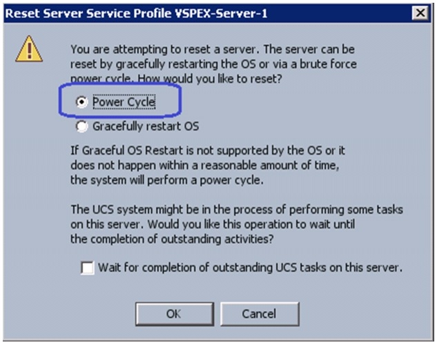
Figure 136 Mapping the ISO Image and Resetting the Server
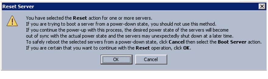
4.
Figure 137 Warning Message for Resetting the Server
5.
Figure 138 Selecting Resetting Option
6.
At this point of time, ESXi installation media would boot from the virtual disk mounted on the KVM. Follow the steps to install ESXi 5.1 hypervisor on the boot LUN. Make sure that you select the boot LUN and not the local disk. You can select all the default parameters or parameters settings as per your requirements.
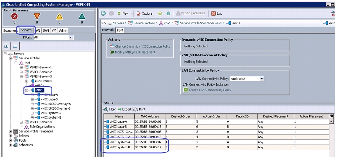
Once the ESXi is installed, login to the system by pressing F2 on the KVM window. You need to configure basic management network for the ESXi host. Make sure that you select two system vNICs.
Figure 139 Selecting Adapters for Default Management Network Connection
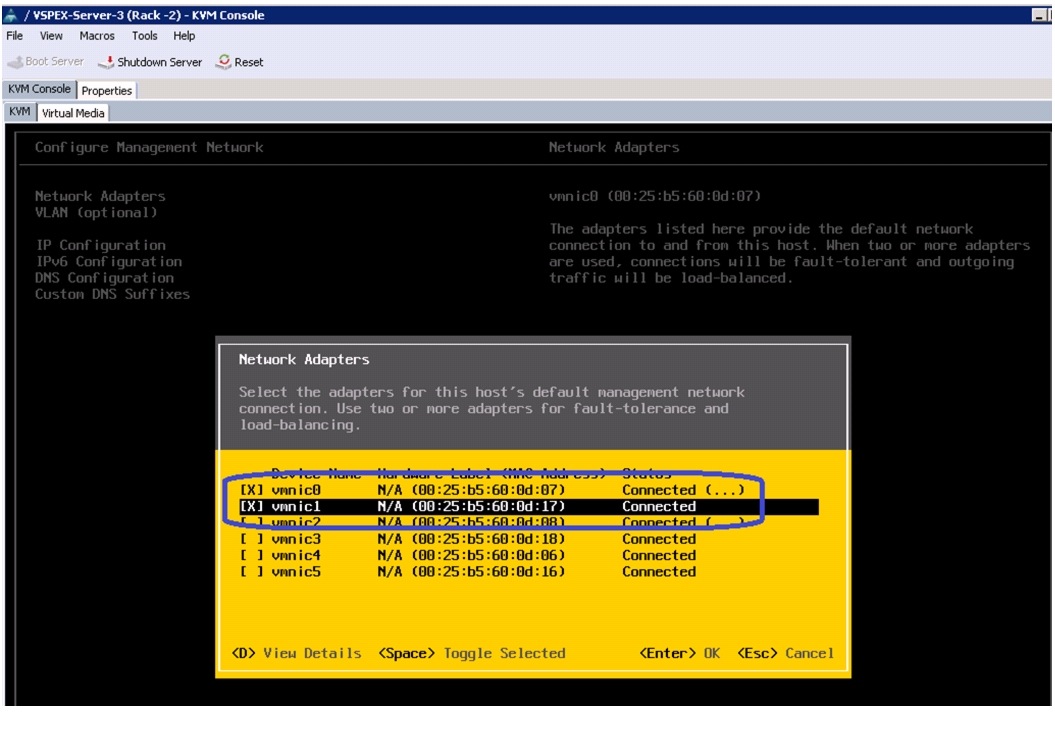
Note
Figure 140 vNIC Names and Their MAC Addresses are Shown in the vNICs Area
7.
VMware vCenter Server Deployment
This section describes the installation of VMware vCenter for VMware environment and to complete the following configuration:
•
•
•
For more information on installing a vCenter Server, see the link:
The following steps provide high level configuration procedure to configure vCenter server:
1.
If the VMware vCenter Server is to be deployed as a virtual machine on an ESXi server installed as part of this solution, then we need to directly connect to an Infrastructure ESXi server using the vSphere Client. Create a virtual machine on the ESXi server with the customer's guest OS configuration, using the Infrastructure server datastore presented from the storage array. The memory and processor requirements for the vCenter Server are dependent on the number of ESXi hosts and virtual machines being managed. The requirements are outlined in the vSphere Installation and Setup Guide.
2.
Install the guest OS on the vCenter host virtual machine. VMware recommends using Windows Server 2012. To ensure that adequate space is available on the vCenter and vSphere, Update Manager installation drive, see vSphere Installation and Setup Guide.
3.
Install vCenter by using the VMware VIMSetup installation media. Easiest method is to install vCenter single sign on, vCenter inventory service and vCenter server using Simple Install. Use the customer-provided username, organization, and vCenter license key when installing vCenter.
4.
To perform license maintenance, log into the vCenter Server and select the Administration - Licensing menu from the vSphere client. Use the vCenter License console to enter the license keys for the ESXi hosts. After this, they can be applied to the ESXi hosts as they are imported into vCenter.
Configuring Cluster, HA and DRS on VMware vCenter
Follow these steps to configure cluster, HA, and DRS on vCenter:
1.
2.
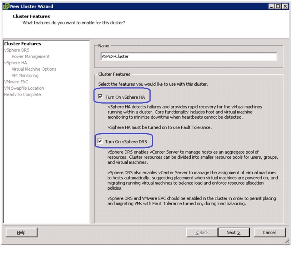
3.
a.
b.
c.
Figure 141 Configuring HA and DRS on Cluster
4.
Figure 142 Adding ESXi Hosts to the Cluster

Virtual Networking Configuration
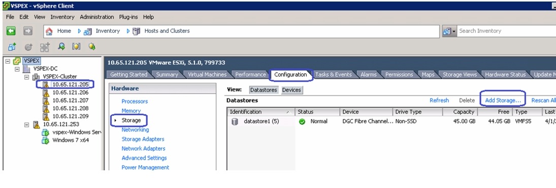
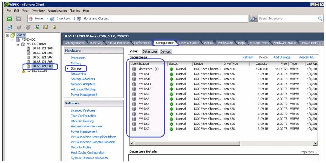
In UCS Manager service profile, we created six vNICs per server for NFS-variant and four vNICs per server for FC-variant. This shows up as six or four network adapters or vmnics in ESXi server. You can see these adapters in the vCenter by choosing Home > Inventory > Hosts and Clusters, select a particular server, click the Configuration tab in the right pane of the window, and click Network Adapters.
Figure 143 Network Adapter Showing vmnics in ESXi Server
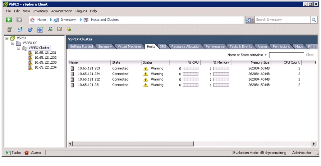
Table 10 shows UCS Manager service profile and vSphere vmnic per ESXi host basis:
*Applicable for the NFS-variant of the solution only.We are show casing two different approaches for the virtual networking layer of this architecture:
1.
2.
Note
We need to create two native vSwitches for virtual network configuration as follows:
1.
2.
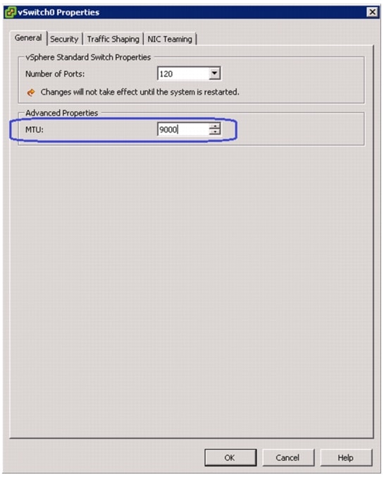
Each vSwitch listed will have two vmnics, one on each fabric for load balancing and high-availability. Also, for vMotion, jumbo MTU needs to be configured in virtual network.
Follow these steps to configure the two vSwitches:
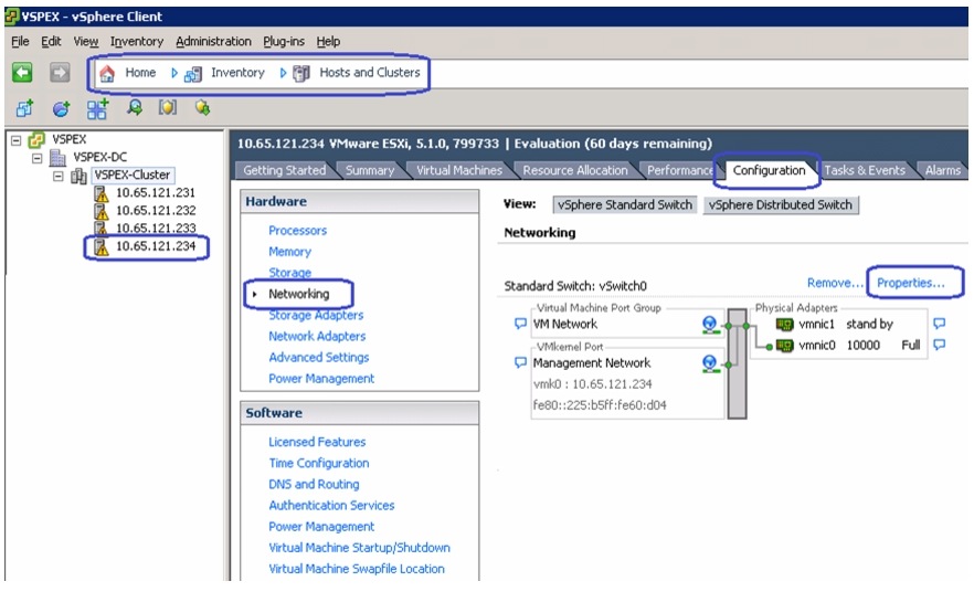
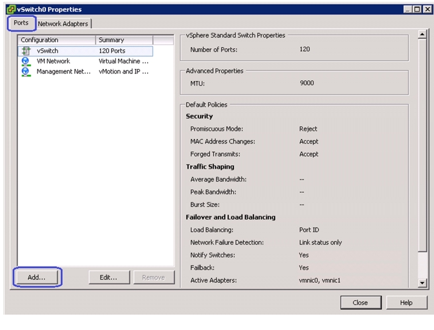
1.
Figure 144 Viewing Details of vSwitch0
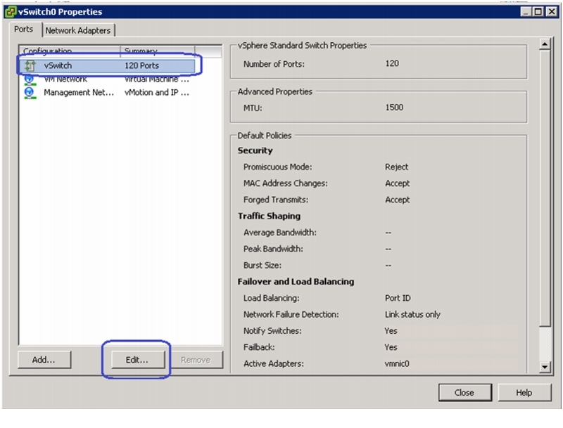
2.
Figure 145 Editing vSwitch0 Properties
3.
Figure 146 Setting Jumbo MTU
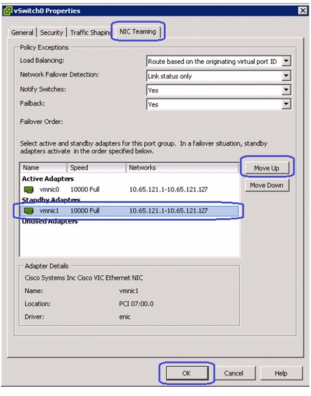
4.
Figure 147 Moving Standby Adapter to Active Adapter
5.
Figure 148 Adding Ports to vSwitch0
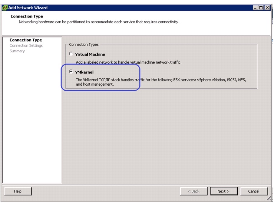
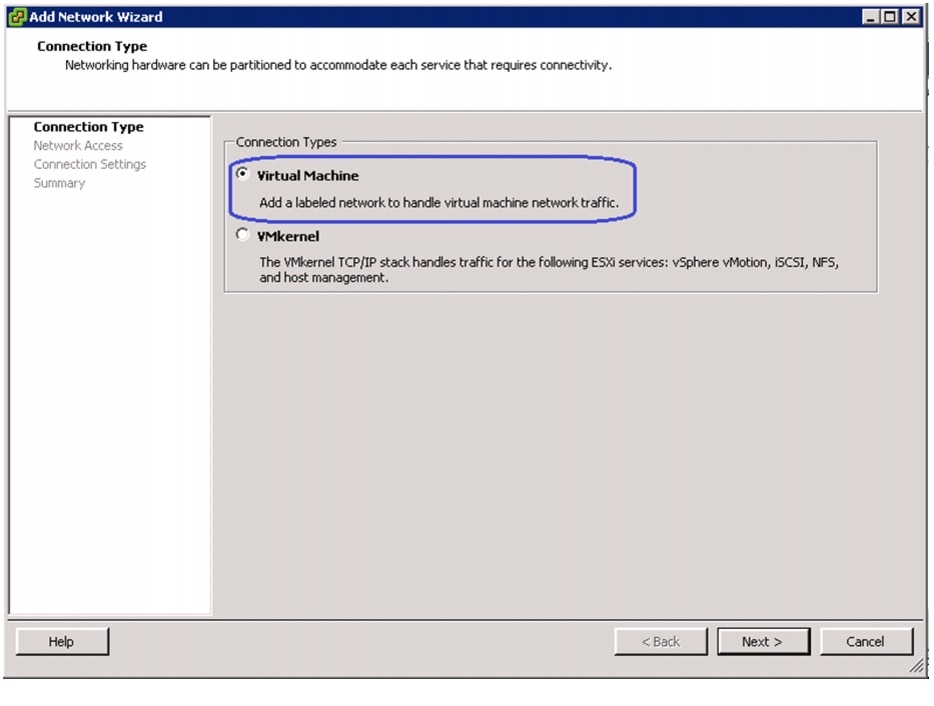
6.
Figure 149 Specifying Connection Type
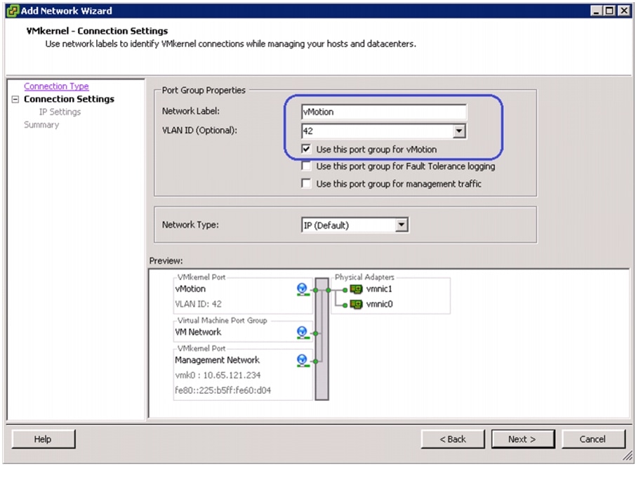
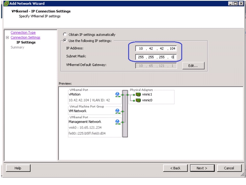
7.
Figure 150 Specifying Port Group Properties for Setting VMkernel Connection
8.
Figure 151 Specifying IP Address and Subnet Mask for Setting VMkernel Connection
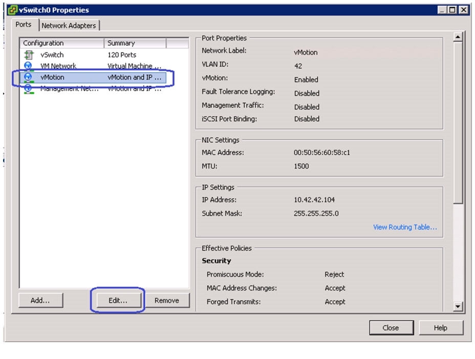
9.
Figure 152 Editing vMotion vSwitch0 to Set Jumbo MTU
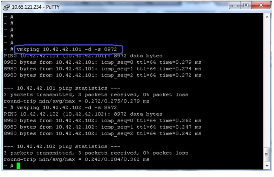
10.
11.
Figure 153 Pinging the VMKernel Port with Jumbo MTU
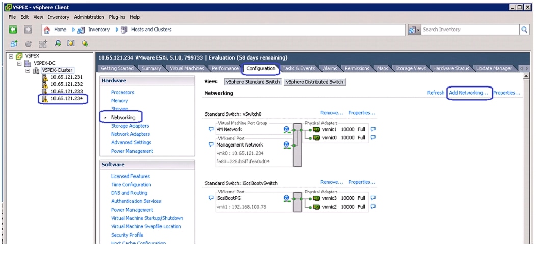
12.
Figure 154 Add Networking in VMware vSphere Client
13.
Figure 155 Specifying the Connection Type
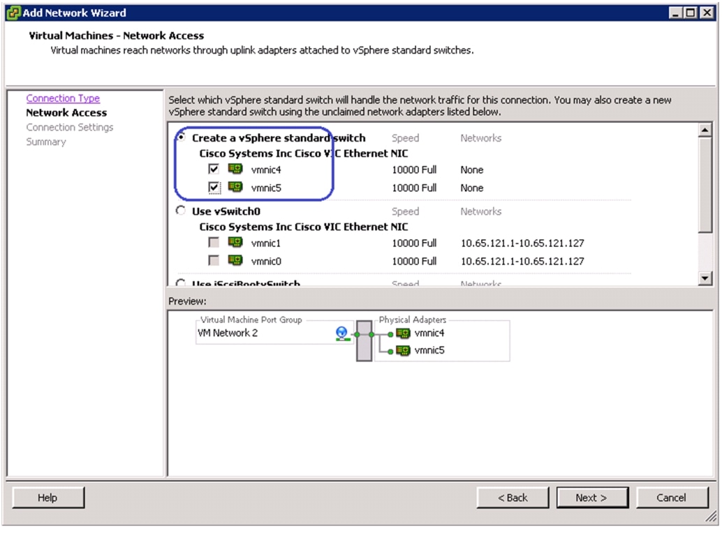
14.
Figure 156 Selecting the vSphere Standard Switch for Handling Network Traffic
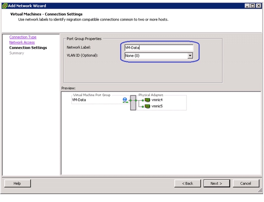
15.
Figure 157 Specifying Port Group Properties
16.
Install and configure Nexus 1000v
Cisco Nexus 1000v is a Cisco's NX-OS based virtual switch that replaces the native vSwitch in the VMware ESXi hosts by a virtual Distributed Switch (vDS). The control plane of Nexus 1000v switch is installed in a VMware Virtual Machine, and is known as Virtual Switching Module (VSM). VSM virtual machine (VSM VM) is available as a VMware OVF template. Following are the major steps to deploy Nexus 1000v architecture:
1.
2.
3.
Install Nexus 1000v VSM VM
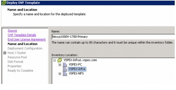
As mentioned before, the Nexus 1000v VSM VM installation media is available as VMware virtual machine OVF template. The VSM VM must be deployed on the infrastructure network, and not on one of the VSPEX ESXi servers. Follow these steps to install VSM VM:
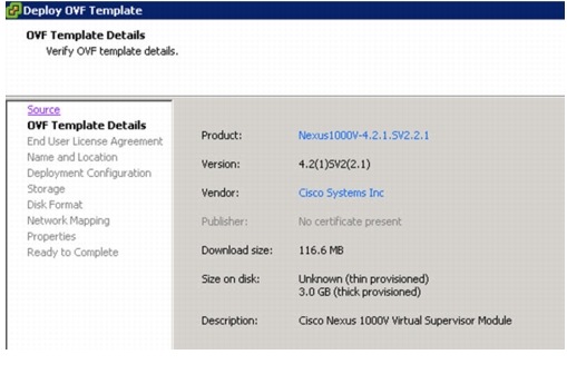
1.
Figure 158 Deploy OVF Template - Verifying OVF Template Details
2.
Figure 159 Deploy OVF Template - Specifying Inventory Location
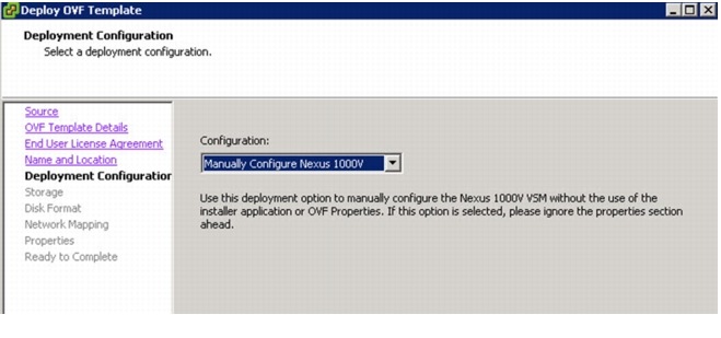
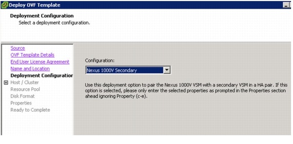
3.
Figure 160 Deploy OVF Template - Choosing Deployment Configuration
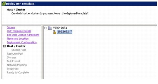
4.
Figure 161 Deploy OVF Template - Choosing the Host
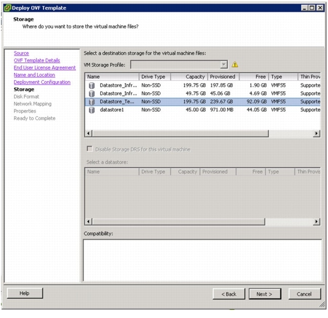
5.
Figure 162 Deploy OVF Template - Choosing the Datastore
6.
Figure 163 Deploy OVF Template - Choosing the Destination Network for Mapping
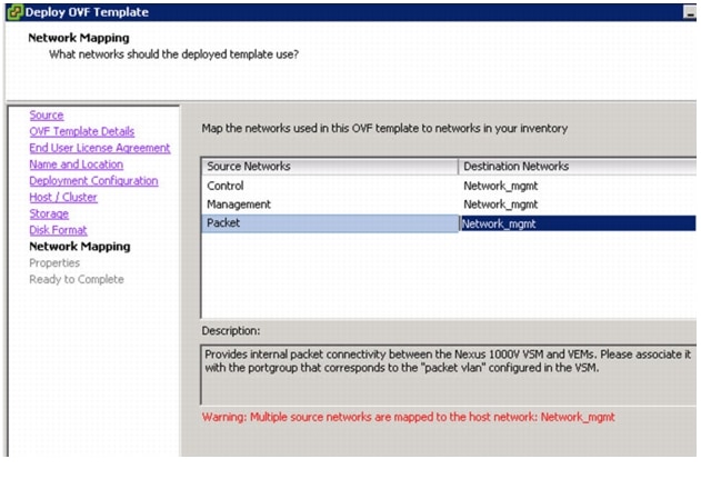
7.
Figure 164 Deploy OVF Template - Entering Details for the Deployment
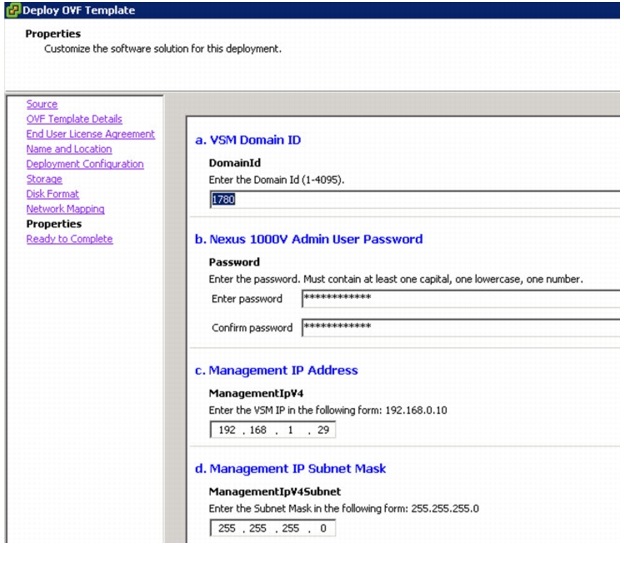
8.
Figure 165 Deploy OVF Template - Verify the Options
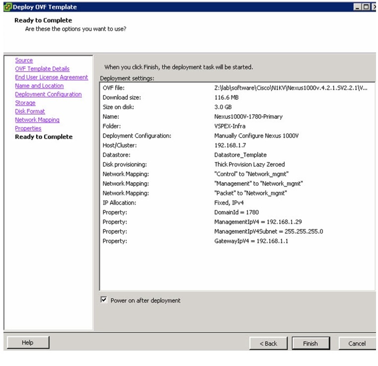
9.
Figure 166 Verifying the Details in the Virtual Machine Console in vCenter
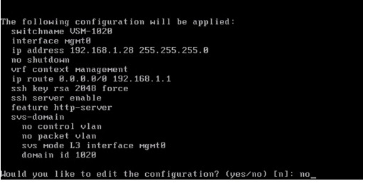
10.
11.
Figure 167 Deploy OVF Template - Choosing Deployment Configuration for Secondary VM
12.
Figure 168 Deploy OVF Template - Entering Details for the Secondary VM Deployment
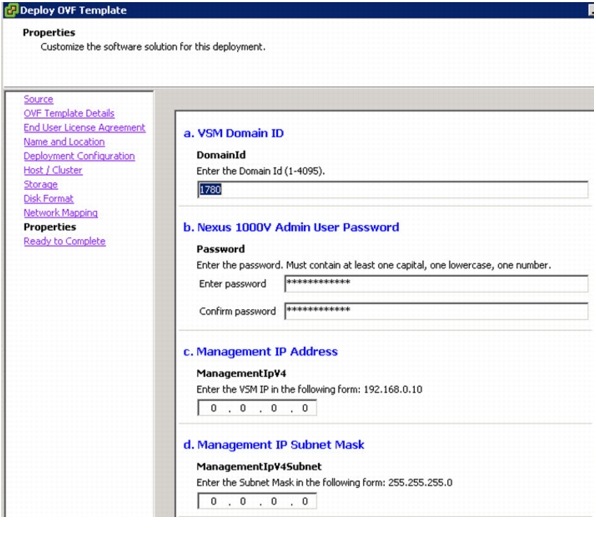
13.
Connecting VSM to vCenter
Once initial setup of VMS VM is completed, we need to add it as a plug-in/ extension in the vCenter:
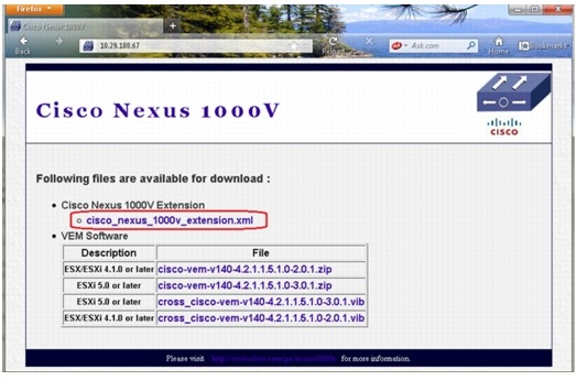
1.
2.
Figure 169 Save the Cisco Nexus Extension XML on your Local Drive
3.
Figure 170
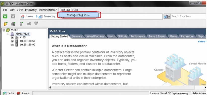
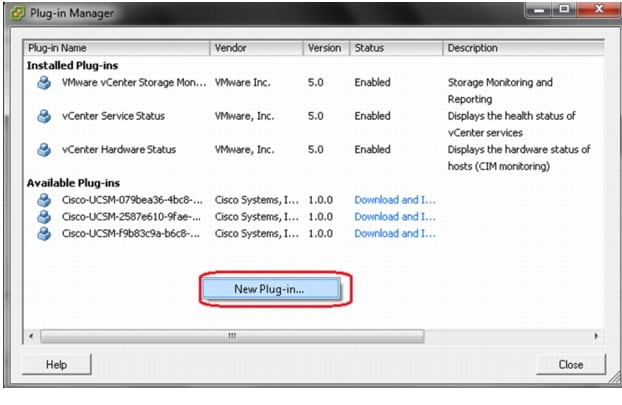
Managing Plug-ins in vCenter
4.
Figure 171 Creating a New Plug-in
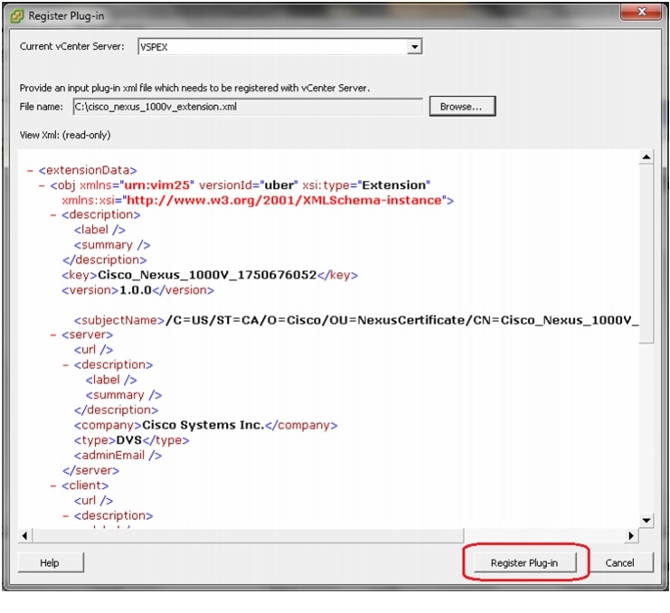
5.
6.
Figure 172 Registering the Downloaded XML File as the New Plug-in
7.
8.
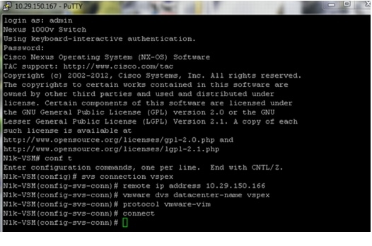
9.
Figure 173 Configuring SVS Connection
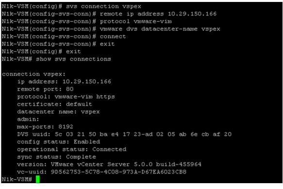
10.
Figure 174 Running show svs connections to Verify the Status
11.
Figure 175 Configuring System-Uplink Port-profile
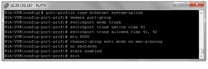
The system-uplink port-profile is applied to the system vNICs of the service profile. MTU 9000 is configured on uplink port-profile to enable jumbo frames. "channel-group auto mode on mac-pinning" is a very important configuration which `pins' the VM vNICs to uplinks on the vDS. MAC pinning feature does static load balancing per vNIC basis. It also provides high-availability by moving the traffic to the alternate adapter when a given fabric is down.
12.
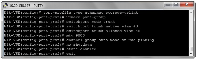
Figure 176 Configuring Storage-Uplink Port-Profile
13.
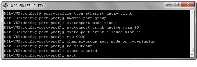
Figure 177 Configuring Data-Uplink Port-Profile
14.
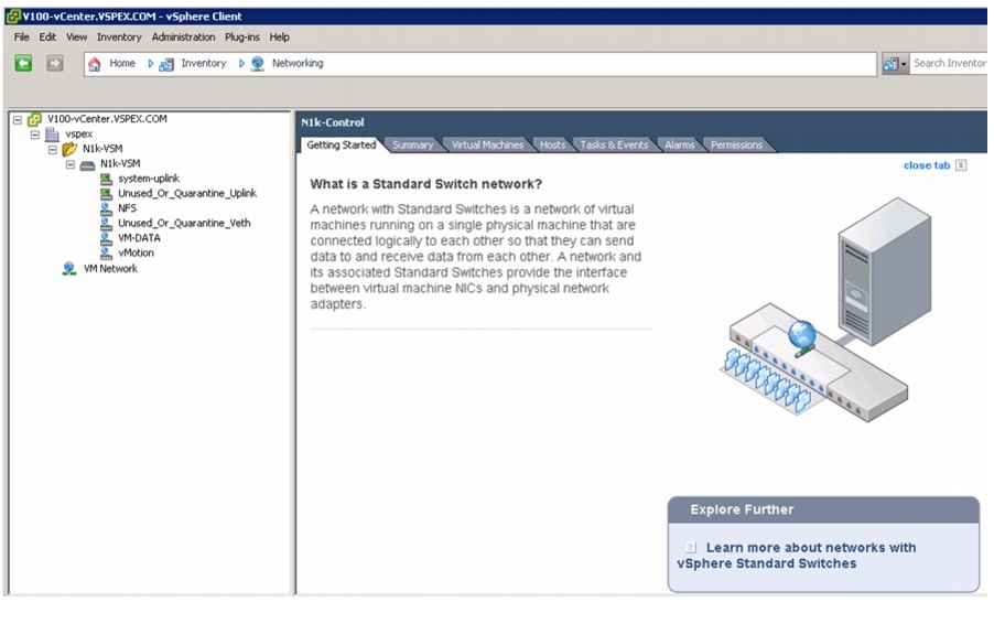
Figure 178 VSM Shown as Virtual Distributed Switch in vCenter
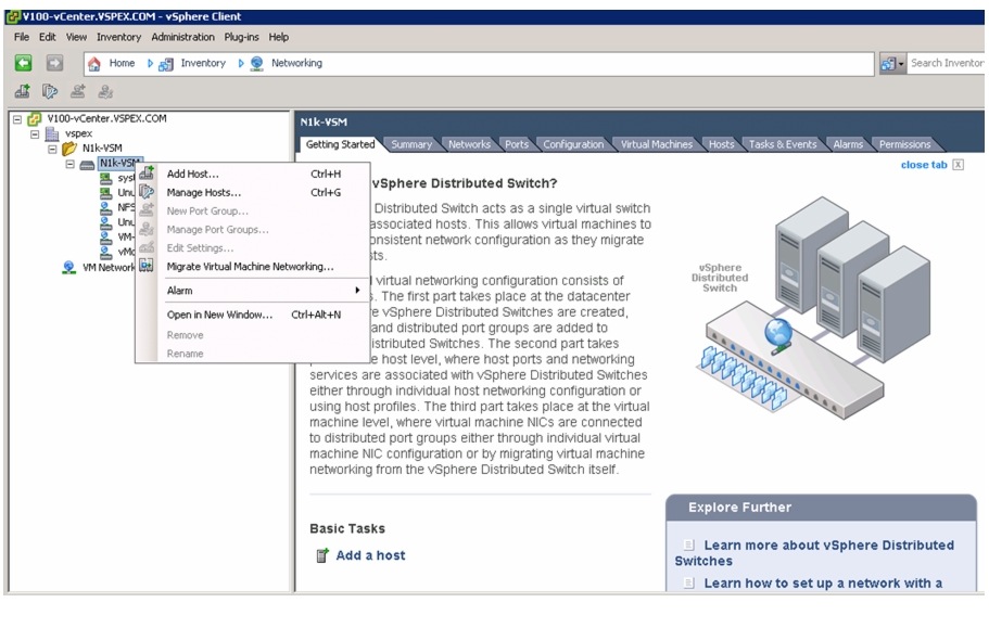
15.
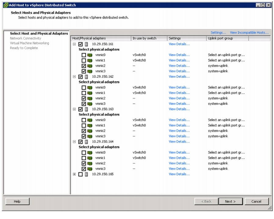
Figure 179 Adding Host to vDS
16.
Figure 180 Selecting Host and Adapters to Add to vDS
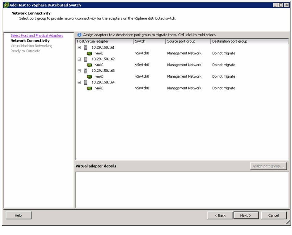
17.
Figure 181 Selecting Port Groups for Network Connectivity
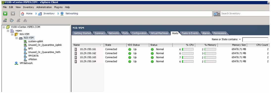
18.
Figure 182 Verifying the Hosts Added to the vDS
Configure Port-Profiles and Add Virtual Machines
The last step of Nexus 1000v configuration and its integration with vCenter is creation of port-profiles and using them in the virtual machines in the vCenter. Note that this is possible only after carving out disk space for VMs on the storage array and deploying the VMs.
To configure port-profiles for VMs, follow these steps:
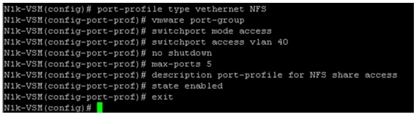
1.
Figure 183 Creating a Port-Profile for NFS Storage Access
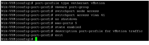
2.
Figure 184 Creating a Port-Profile for vMotion Traffic
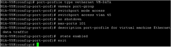
3.
Figure 185 Creating a Port-Profile for VM Data Traffic
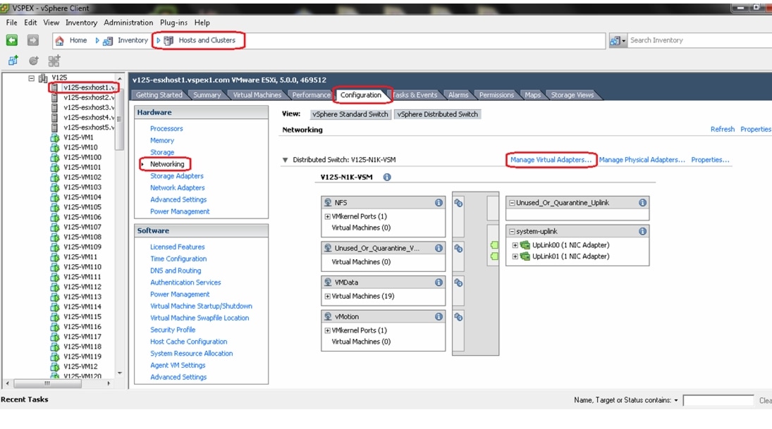
4.
Figure 186 Manage Virtual Adapters in vCenter
5.
6.
7.
8.
9.
10.
11.
12.
13.
Figure 187 Running show port-profile brief to Verify Port-Profile Usage
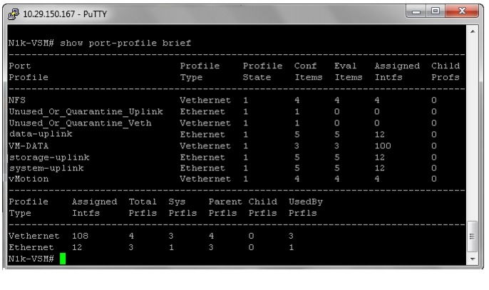
By running the command show port-profile name <uplink-port-profile-name>, you can see the implicit creation of port-channels per ESXi host basis due to the "channel-group auto mode on mac-pinning" CLI configured under the port-profile. In addition to the Ethernet uplink ports, port-channels are also listed as assigned interfaces. Port-channel status can be further viewed/ validated using show port-channel brief command from VSM VM.
Configure storage for VM data stores, install and instantiate VMs from vCenter
This subsection is divided in two subsections:
1.
2.
Configure VM Datastores for FC-Variant of the Solution
See Figure 13 for Storage Architecture for 300 VMs on VNX 5400 to have a high-level overview of storage architecture. Follow these steps to configure the data store:
1.
Figure 188 Creating Storage Pools
2.
Figure 189 Details for Creating Storage Pool
3.
4.
Figure 190 Creating LUNs for VM Datastore
5.
Figure 191 Details for Creating LUN
6.
7.
Figure 192 Adding the Created LUN to Storage Group
8.
Figure 193 Moving Storage Groups to Selected Storage Groups
9.
Figure 194 Storage Group and Host Information
10.
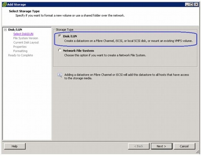
Figure 195 Adding Storage
11.
Figure 196 Choose the Storage Type
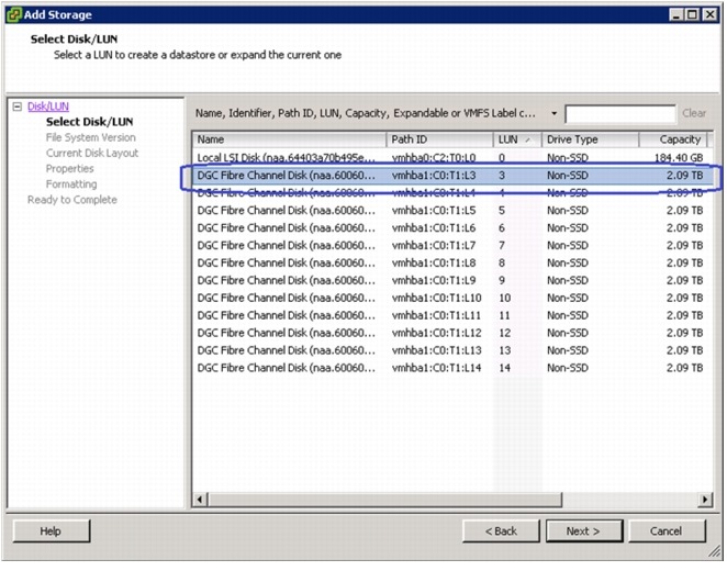
12.
Figure 197 Selecting a LUN
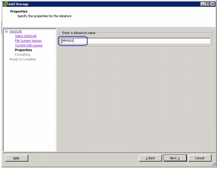
13.
Figure 198 Specifying a Name for Datastore
14.
Figure 199 Datastores Added to the Hosts
Configuring VM Datastore for the NFS-Variant of the Solution
1.
Figure 200 Selecting Storage Pools in EMC Unisphere
2.
Figure 201 Creating Storage Pools
3.
Figure 202 Details for Creating Storage Pools

4.
5.
Figure 203 Creating LUNs form Newly Created Pool
6.
Figure 204 Details for Creating LUN
7.
Figure 205 Adding Pools and LUNs to Storage Group
8.
Figure 206 Moving Storage Groups to Selected Storage Groups
9.
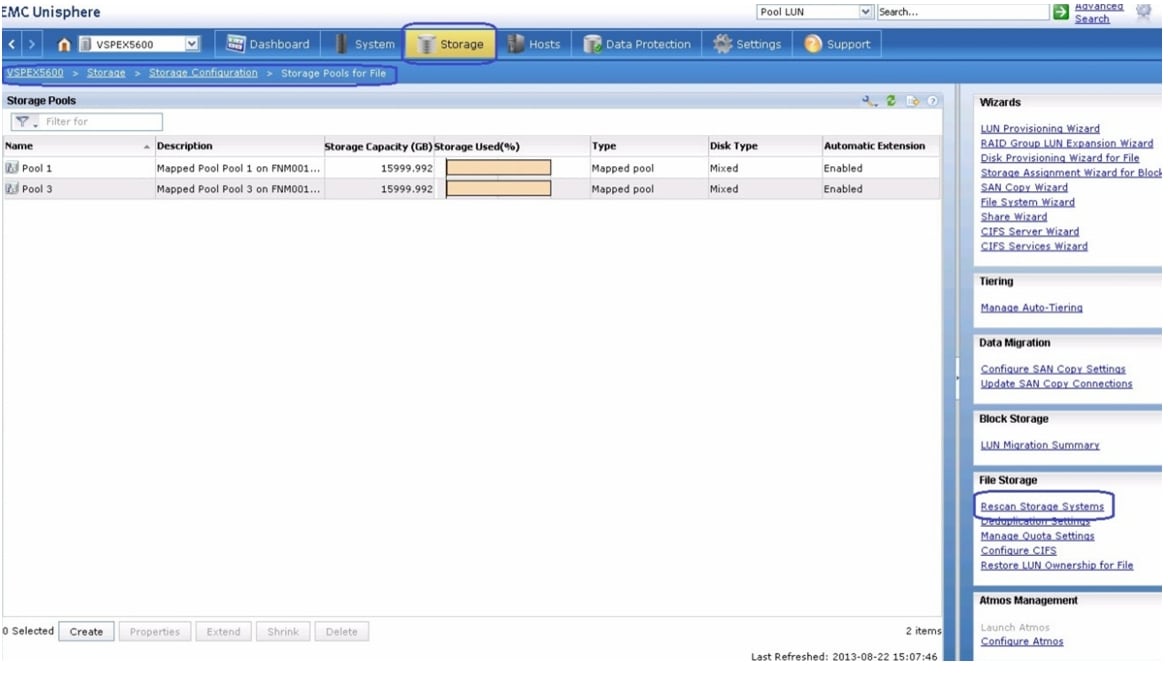
Figure 207 Created Storage Pools are Shown in Storage Pools for File Window of EMC Unisphere
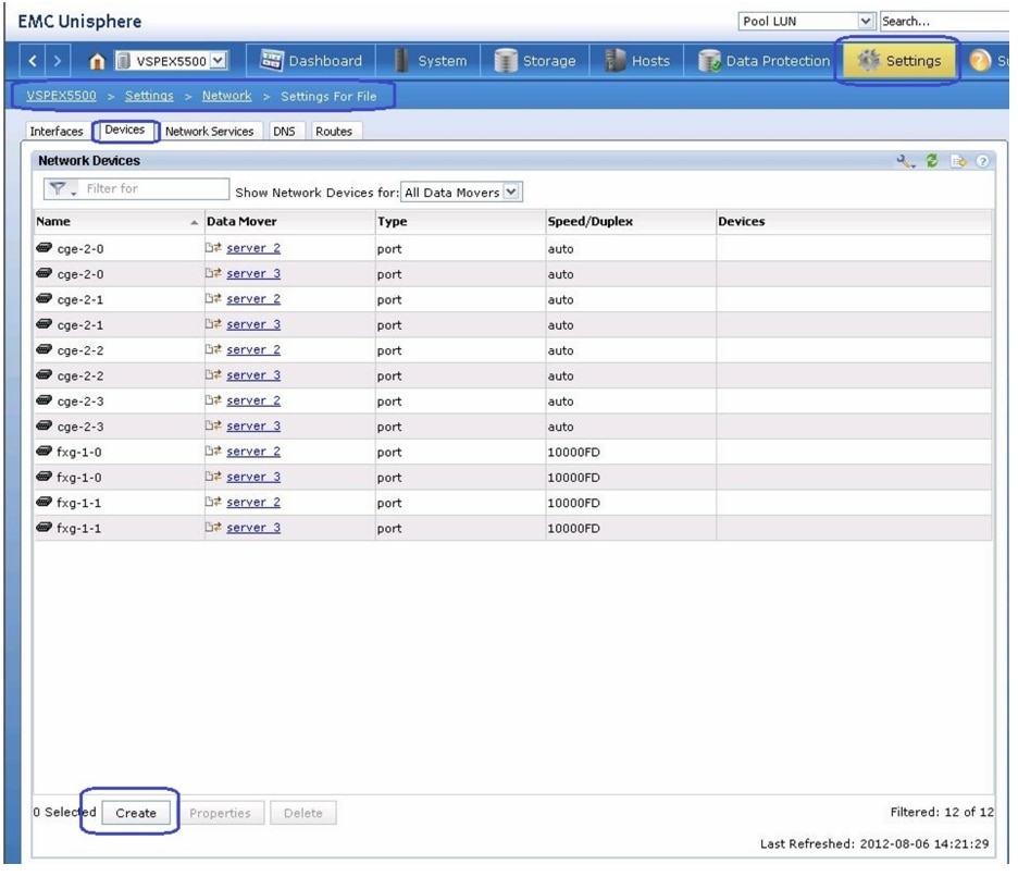
10.
Figure 208 Creating LACP Interface
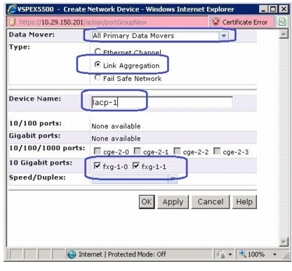
11.
Figure 209 Creating Network Device
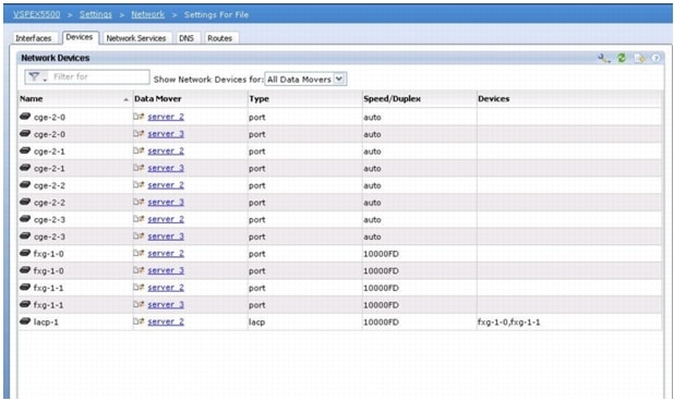
12.
Figure 210 Created LACP Network Device is Shown Under Network Devices
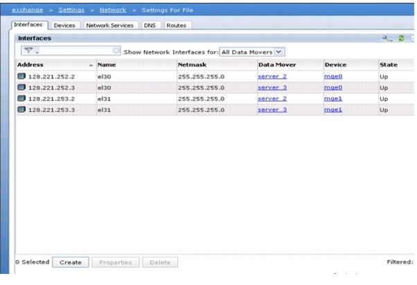
13.
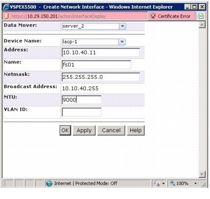
Figure 211 Creating Network Interface
14.
Figure 212 Details for Creating Network Interface
15.
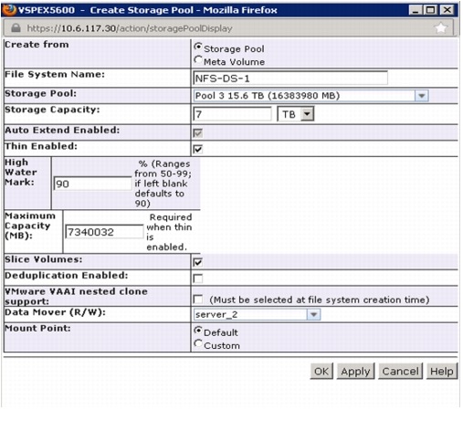
From the Create File System window, click the Storage Pool radio button and Specify File System Name as NFS-DS-1 for Virtual machine datastore. Then, Select Storage Pool from the drop-down list. Specify Storage Capacity as 5 TB, check the check box Thin Enabled, 7340032 MB (7TB) as Max Capacity, and choose Data Mover as Server_2. Click OK to create NFS-DS-1 File system.
Figure 213 Details for Creating Storage Pool
16.
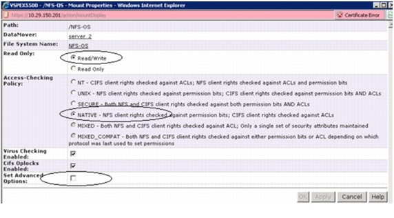
17.
Figure 214 Select /NFS-OS to Enable Direct Writes

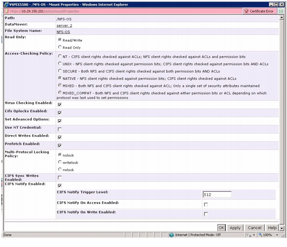
18.
Figure 215 /NFS-OS Mount Properties - Part 1
19.
Figure 216 /NFS-OS Mount Properties - Part 2
20.
21.
Figure 217 Creating NFS Exports
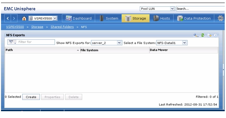
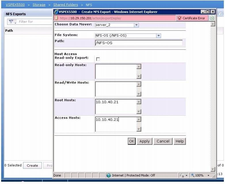
22.
Figure 218 Details for Creating NFS Export
Template-Based Deployments for Rapid Provisioning
Figure 219 Rapid Provisioning
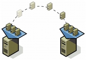
In an environment with established procedures, deploying new application servers can be streamlined, but can still take many hours or days to complete. Not only must you complete an OS installation, but downloading and installing service packs and security updates can add a significant amount of time. Many applications require features that are not installed with Windows by default and must be installed prior to installing the applications. Inevitably, those features require more security updates and patches. By the time all deployment aspects are considered, more time is spent waiting for downloads and installs than is spent configuring the application.
Virtual machine templates can help speed up this process by eliminating most of these monotonous tasks. By completing the core installation requirements, typically to the point where the application is ready to be installed, you can create a golden image which can be sealed and used as a template for all of your virtual machines. Depending on how granular you want to make a specific template, the time to deployment can be as little as the time it takes to install, configure, and validate the application. You can use PowerShell tools and VMware vSphere Power CLI to bring the time and manual effort down dramatically.
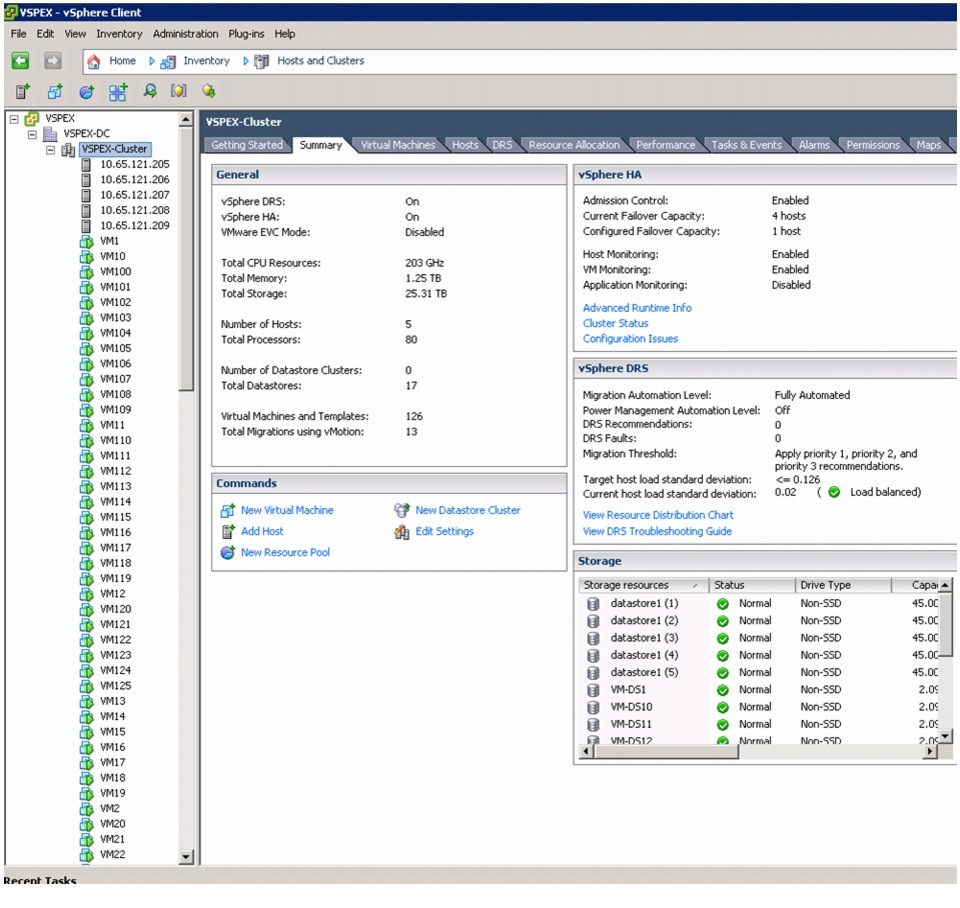
Make sure that the VMs are spread across different VM datastores to properly load-balance the storage usage. The final snapshot of VMs in a cluster looks like Figure 220.
Figure 220 Summary Window Showing VMs in the Cluster in vCenter
Validating Cisco Solution for EMC VSPEX VMware Architectures
This section provides a list of items that should be reviewed when the solution has been configured. The goal of this section is to verify the configuration and functionality of specific aspects of the solution, and ensure that the configuration supports core availability requirements.
Post Install Checklist
The following configuration items are critical to functionality of the solution, and should be verified before deploying for production.
•
•
•
Verify the Redundancy of the Solution Components
Following redundancy checks were performed at the Cisco lab to verify solution robustness. A continuous ping from VM to VM, and vCenter to ESXi hosts should not show significant failures (one or two ping drops might be observed at times, during FI reboot). Also, all the datastores must be visible and accessible from all the hosts at all the time.
1.
2.
3.
4.
5.
6.
7.
Cisco Validation Test Profile
"vdbench" testing tool was used with Windows Server 2012 to test scaling of the solution in Cisco labs. Table 11 details on the test profile used.
Bill of Material
Table 12 gives the list of the components used in this CVD. The number of actual Cisco UCS servers will vary depending on the size of the architecture. For actual number of servers and chassis, see Table 3.
Customer Configuration Data Sheet
Before you start the configuration, gather the customer-specific network and host configuration information. Table 13, Table 14, Table 15, Table 16, Table 17, Table 18, Table 19 provide information on assembling the required network, host address, numbering, and naming information. This worksheet can also be used as a "leave behind" document for future reference.
Table 13 Common Server Information
Domain Controller
DNS Primary
DNS Secondary
DHCP
NTP
SMTP
SNMP
vCenter Console
SQL Server
Table 14 ESXi Server Information
ESXi
Host 1
ESXi
Host 2
Table 15 Array Information
Admin account
Management IP
Storage pool name
Datastore name
NFS Server IP
References
Cisco UCS:
http://www.cisco.com/en/US/solutions/ns340/ns517/ns224/ns944/unified_computing.html
VMware vSphere:
http://www.vmware.com/products/vsphere/overview.html
Cisco Nexus 5000 Series NX-OS Software Configuration Guide:
EMC VNX 5xxx series resources:
http://www.emc.com/storage/vnx/vnx-series.htm#!resources
Microsoft SQL Server installation guide:
http://msdn.microsoft.com/en-us/library/ms143219.aspx