- Title
- Contents
- What�s in This Guide
- Using the Cisco TelePresence TX System Administration Interface
- Understanding the Fields In the Cisco TelePresence TX System Administration Interface
- Device Information
- TX Software Features
- Configuring the Cisco TelePresence TX System
- Monitoring the Cisco TelePresence TX System
- Satellite Licenses for the Cisco TelePresence TX System
- Glossary
- Index
- Contents
- 1080p 60 Main Video
- High-Definition Presentation
- HD Presentation Overview
- Available Presentation Cables, Supported Presentation Devices, and Tested Adapters
- Resolution Support For Digital and VGA Cables
- Connecting the Audio Cable to the Codec
- Required Configuration For HD Presentation
- Scaling HD Presentation Video Resolution
- Bandwidth Requirements for the HD Presentation Feature
- Video Bandwidth Allocation Weights
- 802.1X Authentication
TX Software Features
This chapter includes an overview of, and configuration information for, TX software features.
This chapter includes information only about the features that require an overview or detailed configuration steps. For a description of all features that are introduced in a specific TX software release, see the Release Notes for that release.
1080p 60 Main Video
In software releases prior to TX release 6, a Cisco TelePresence endpoint can send and receive main video at a maximum frame rate of 30 frames per second (fps). Systems running TX software release 6 and above can send and receive video at 60 fps with 1080p quality (1080p 60).

Note If your conferences appear darker after you start using 1080p 60 video, you might have to readjust the white balance for the system cameras. To perform this procedure, see the “Adjusting the White Balance for Your System” section.
Systems Supporting 1080p 60
The following systems running TX software can send and receive main video at 1080p 60 during a point-to-point call:
- Cisco TelePresence System TX1300 47
- Cisco TelePresence System TX1310 65
- Cisco TelePresence System TX9000
- Cisco TelePresence System TX9200
The following systems can send and receive main video at 1080p 60 with systems running TX software during a point-to-point call:
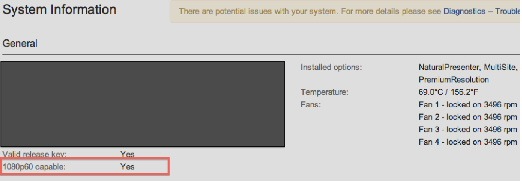
To determine if your system has the latest hardware, log in to the administration console for the system and navigate to the System Information window. If the system can support 1080p 60, the 1080p60 capable field is set to Yes , as shown in Figure 4-1.
Figure 4-1 Checking 1080p 60 Capability for C60 and C90 Codec-Based Systems
1080p 60 is currently supported only for point-to-point calls. 720p 60 is supported for point-to-point calls and multipoint calls that are placed through the Cisco TelePresence Server version 2.3.
For more information, refer to the Release Notes for TC6 software at the following URL:
http://www.cisco.com/en/US/docs/telepresence/endpoint/software/tc6/release_notes/
tc_software_release_notes_tc6.pdf
The following systems can send and receive main video at a frame rate of 60 fps with 720p quality (720p 60) with systems running TX software during a point-to-point-call:
Note To support the 60 fps main video feature, the Cisco TelePresence endpoints listed above must use the camera(s) that originally ship with the endpoint. The 60 fps main video feature does not support third-party cameras.
Table 4-1 shows the send and receive main video resolution and frame rate of the 60 fps-capable Cisco TelePresence systems.
TX1300 47, TX1310 65, TX9000, TX92000, SX20 endpoints, and C60 and C90 endpoints with the latest hardware |
1080p@60 fps1 |
720p@60 fps 1 |
|
C20, C40, EX60, and EX90 endpoints, and C60 and C90 endpoints with earlier hardware |
720p@60 fps 1 |
720p@60 fps 1 |
|
Benefits
The 60 fps main video feature provides the following benefits:
–![]() Sharper images and increased number of pixels, which create a perception that the video is of a higher resolution than it actually is.
Sharper images and increased number of pixels, which create a perception that the video is of a higher resolution than it actually is.
–![]() Smoother motion handling, less blurriness.
Smoother motion handling, less blurriness.
Note The bandwidth requirements for 1080p 60 is 1.5 times higher than that for 1080p 30. If bandwidth conservation is a concern for your Cisco TelePresence environment, you must carefully weigh the benefits of a better video experience against the increased bandwidth requirements of 60 fps and choose accordingly.
As an alternative, 720p 60 fps can provide a video experience comparable to 1080p 30 fps for approximately 5 to 15 percent less bandwidth. For more information about bandwidth requirements, see the “Understanding How Endpoints Determine fps and Video Quality” section
Required Configuration
The following configuration is required to enable the 60 fps main video feature in your Cisco TelePresence environment:
- For the TX endpoints listed in the “Systems Supporting 1080p 60” section, make the following changes in Unified CM version 8.6(2a)SU2 or later:
–![]() Set Main Display Frames Per Second in the Phone Configuration page to “60 fps main”. (To access the Phone Configuration page, from Cisco Unified CM Administration, choose Device > Phone. Search for a device, then click on the device name, which brings up the Phone Configuration page.)
Set Main Display Frames Per Second in the Phone Configuration page to “60 fps main”. (To access the Phone Configuration page, from Cisco Unified CM Administration, choose Device > Phone. Search for a device, then click on the device name, which brings up the Phone Configuration page.)
–![]() Set Video Bandwidth Allocation Weights in the Phone Configuration page appropriately. For more information about this parameter, see the “Video Bandwidth Allocation Weights” section.
Set Video Bandwidth Allocation Weights in the Phone Configuration page appropriately. For more information about this parameter, see the “Video Bandwidth Allocation Weights” section.
- For the 60 fps-capable C and SX endpoints listed in the “Systems Supporting 1080p 60” section, make the following configuration changes:
–![]() Install a premium resolution option key on each endpoint.
Install a premium resolution option key on each endpoint.
–![]() Set the call rate to 6000 Kbps by logging into the administrative interface for your system and navigating to
Configuration > System Configuration
, clicking the
Conference 1
choice in the left navigation bar, and verifying that the Rate setting in the
DefaultCall
area is set to 6000.
Set the call rate to 6000 Kbps by logging into the administrative interface for your system and navigating to
Configuration > System Configuration
, clicking the
Conference 1
choice in the left navigation bar, and verifying that the Rate setting in the
DefaultCall
area is set to 6000.
–![]() Set the camera for to 60 fps for the camera by logging into the administrative interface for your system and navigating to
Configuration > System Configuration
, clicking the
Video
choice in the left navigation bar, and verifying the following settings:
Set the camera for to 60 fps for the camera by logging into the administrative interface for your system and navigating to
Configuration > System Configuration
, clicking the
Video
choice in the left navigation bar, and verifying the following settings:
In the Source 1 area, verify that Quality is set to Motion .
In the Source 1 > Optimal Definition area, verify that Profile is set to High and Threshold60fps is set to 1280_720 .
- For the Cisco TelePresence Server, make the following changes in the System Settings page of the Cisco TelePresence Server administration interface:
–![]() Click the
Configuration
tab and check the
Enable 60 fps
check box.
Click the
Configuration
tab and check the
Enable 60 fps
check box.
–![]() From the HD mode drop-down menu, choose
Full HD
.
From the HD mode drop-down menu, choose
Full HD
.
After performing the required configuration, 60 fps-capable Cisco TelePresence endpoints can send and receive main video at a maximum frame rate of 60 fps. The actual usage of 60 fps for sending and receiving depends on the following factors:
- The setting of Video Bandwidth Allocation Weights in Unified CM.
- For point-to-point calls, the results of the call setup negotiation with the receiving endpoint.
- For multipoint calls, the results of the call setup negotiation with the Cisco TelePresence Server.
- Current network conditions (bandwidth).
For more information about the call setup negotiation and bandwidth, see the “Understanding How Endpoints Determine fps and Video Quality” section.
Lighting Considerations
To optimize your Cisco TelePresence environment for 60 fps main video, a lighting level of 250 lux is acceptable, but a lighting level of at least 350 lux is recommended.
Understanding How Endpoints Determine fps and Video Quality
During Cisco TelePresence call setup, the sending and receiving endpoints determine the fps (30 or 60 fps) and video quality (1080p or 720p) in which the video streams are sent and received.
The determination is made as a result of the following factors:
- The amount of Transport Independent Application Specific (TIAS) bandwidth that is negotiated between the sending and receiving endpoints.
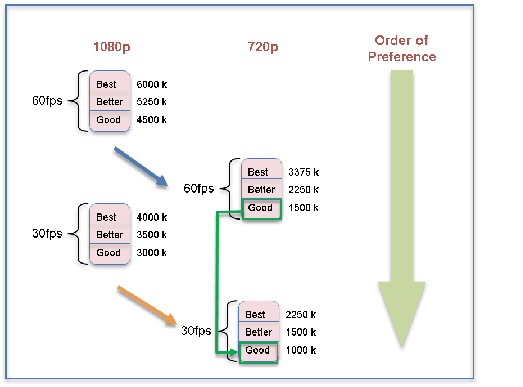
The minimum amount of bandwidth is determined by the settings of Main Display Frames Per Second and Quality (Per Display) in the Phone Configuration page of Unified CM. Figure 4-2 and Table 4-3 show the bandwidth requirements based on the Unified CM configuration for 30 fps and 60 fps calls.
- The maximum frame size that the network and system can accommodate.
- The negotiation of the video resolution and frame rate (in fps) by the sending and receiving endpoints.
- The maximum bit rate allowed in the Region settings for your device in Unified CM. These settings are applied to the Device Pool, which in turn are applied to your device.
To find your region settings, log in to the Cisco Unified CM Administration GUI and navigate to System > Region . The maximum rate is the value shown in the Max Video Call Bit Rate (Includes Audio) field.
Table 4-2 shows the three criteria that are required in the first three columns of the table, and the resulting video stream that can be sent in the fourth column of the table.
If any of the factors do not meet the minimum requirements, the system attempts to send and receive video at the next lowest rate as shown in Table 4-4 .
For example, if the system and network cannot meet the minimum requirements to send a video stream with the maximum video quality of 1080p 60, the system attempts to negotiate a video stream of 720p 60. If the system cannot meet the requirements to send a video stream of 720p 60, it attempts to negotiate a video stream of 720p 30as shown in Table 4-4 .
Note 720p Lite and other lower resolutions such as 360p do not support the 60 fps main video feature because of bandwidth restrictions.
If a call is put on hold, then resumed, the amount of bandwidth is re-negotiated using the same factors.
Figure 4-2 Bandwidth Requirements Per Unified CM Quality (Per Display) Requirements
Under the following circumstances, the 60 fps-capable Cisco TelePresence endpoints and device send the main video stream at 30 fps:
- When in a call with an endpoint or device that supports a maximum frame rate of 30 fps.
- When in a call with a Cisco TelePresence endpoint that is registered with a Cisco Unified Communications Manager (Unified CM) version that does not support 60 fps as a setting for Main Display Frames Per Second in the Phone Configuration page.
- When in a call with a Cisco TelePresence endpoint that is registered with a Unified CM version that supports 60 fps but “30 fps main” is the setting for Main Display Frames Per Second in the Phone Configuration page.
High-Definition Presentation
This section provides you with information about the supported presentation resolutions and presentation audio and video cables and includes the following sections:
- HD Presentation Overview
- Available Presentation Cables, Supported Presentation Devices, and Tested Adapters
- Resolution Support For Digital and VGA Cables
- Connecting the Audio Cable to the Codec
- Required Configuration For HD Presentation
- Scaling HD Presentation Video Resolution
- Bandwidth Requirements for the HD Presentation Feature
HD Presentation Overview
Systems running TX software support high-definition (HD) presentation to a maximum of 1080p resolution at 30 frames per second (1080p 30). The following systems support the HD presentation feature:
- Cisco TelePresence System 500-32
- Cisco TelePresence System TX1300 47
- Cisco TelePresence System TX1310 65
- Cisco TelePresence System TX9000
- Cisco TelePresence System TX9200
Two presentation cable types are supported for systems running TX software:
- A digital cable with an attached audio cable that connects to the codec with an HDMI connector
- An analog cable with an attached audio cable that connects to the codec with a VGA connector.
For more information, see the “Available Presentation Cables, Supported Presentation Devices, and Tested Adapters” section. For information about the resolutions that are supported by each cable, see the “Resolution Support For Digital and VGA Cables” section.
The following Cisco TelePresence endpoints are tested and known to interoperate with the TX endpoints that can send an HD presentation video stream:
While these endpoints are supported, the received rate for that endpoints, and the quality of the HD presentation, depend on one or more of the following factors:
- The negotiated bandwidth for the call. See Table 4-8 for the bandwidth requirements for HD presentations.
- Any bandwidth and fps settings as set in Unified CM (for example, the Quality (per Display) setting for the CTS system) and/or on the endpoint itself (for example, the MainChannel Weight and PresentationChannel Weight settings for the Cisco TelePresence EX Series).
- The maximum received presentation resolution and frame rate that the other endpoint can receive. To determine the maximum received presentation resolution and frame rate that is supported for a particular system, consult the data sheet for that system.
Note Some presentation resolutions do not take up the full space of the presentation display area. For example, if a laptop that is sending the presentation is set to a resolution of 1600x900, and the presentation display is set to a resolution of 1920x1080, the image shown on the display is 1600x900 pixels with a black border around it to make a total pixel size of 1920x1080.
Available Presentation Cables, Supported Presentation Devices, and Tested Adapters
The following presentation cables are available to use with systems running TX 6 software:
- HDMI-to-HDMI (part number CTS-HDMIHDMI-A=) with audio cable attached
- DisplayPort-to-HDMI (part number CTS-CAB-DPHDMI-A=) with audio cable attached
- Mini DisplayPort-to-HDMI (part number MDPHDMI-A=) with audio cable attached
Note If you use any of the HDMI cables, connect the audio cable to the audio connector labeled “Aux” on the codec. For more information, see the “Connecting the Audio Cable to the Codec” section.
Note If you use the VGA cable, connect the audio cable to the audio connector with a PC icon on the codec. For more information, see the “Connecting the Audio Cable to the Codec” section.
The following presentation devices have been tested with the following cables:
- Laptop (PC) using an HDMI-to-HDMI cable and a DisplayPort-to-HDMI adapter
- MacBook Air and MacBook Pro using the following cables:
–![]() An HDMI-to-HDMI cable with a passive Mini DisplayPort-to-HDMI adapter
An HDMI-to-HDMI cable with a passive Mini DisplayPort-to-HDMI adapter
–![]() A DisplayPort-to-HDMI cable with a Mini DisplayPort-to-DisplayPort adapter
A DisplayPort-to-HDMI cable with a Mini DisplayPort-to-DisplayPort adapter
–![]() A Mini DisplayPort-to-HDMI cable
A Mini DisplayPort-to-HDMI cable
Note Some Apple devices showed flickering on the screen when being used for presentation sharing. If you encounter this issue, change the resolution quality to a lower resolution.
If an adapter is required, Cisco recommends using a passive adapter, rather than an active adapter that changes or enhances the video signal. Active adapters can cause issues with the presentation being shared immediately after the adapter is connected to the presentation cable.
The following adapters have been tested with the HDMI-to-HDMI cable:
The following adapter has been tested with the Mini DisplayPort-to-HDMI cable:
Resolution Support For Digital and VGA Cables
In software releases prior to TX release 6, the proportional relationship between the width and height (also known as aspect ratio ) of the presentation display was 4:3. For the HD presentation display, the aspect ratio is 16:9.
Table 4-5 outlines the common resolutions shared by the presentation devices, the corresponding aspect ratios, and the presentation cables that support the resolutions.
The actual size of the presentation display depends if the Swap Picture In Presentation (PIP) feature is disabled or enabled.
Connecting the Audio Cable to the Codec
Starting with TX software release 6, you connect the audio cable to different connections based on the type of cable.
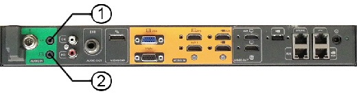
- For HDMI cables, connect the audio cable to the AUDIO IN connector labeled “Aux” (callout 1 in Figure 4-3).
- For VGA cables, connect the audio cable to the AUDIO IN connector with a PC icon (callout 2 in Figure 4-3).
Note For the TX9000 and TX9200 systems, the audio connections plug into the TS1 codec, while the video connections plug into the TS4 codec. For more information, refer to the “Connecting and Routing the Cables” chapter of the Cisco TelePresence System TX9000 and TX9200 Assembly, First-Time Setup, and Field-Replaceable Unit Guide.
Figure 4-3 Audio Connections for the Presentation Cable
Required Configuration For HD Presentation
In software releases prior to TX release 6, if both Binary Floor Control Protocol (BFCP) and TelePresence Interoperability Protocol (TIP) are negotiated for a call, TIP takes precedence, and BFCP is not used to control presentation. BFCP is the preferred protocol for controlling the presentation for systems that run TX software.
To support HD presentation, Unified CM version 8.6(2a)SU2 and later is required.
Table 4-6 describes the Unified CM configuration that enables HD presentation to function on TX endpoints.
For each TX endpoint, use the Standard SIP Profile (not the Standard SIP BFCP Profile) for the SIP profile. |
If using Unified CM 8.6(2a)SU2 and later (the recommended configuration), if you specify the Standard SIP BFCP profile, calls might be dropped and BFCP might not function properly. |
When setting up your endpoint in Unified CM, make sure that you check the Allow Presentation Sharing Using BFCP check box in the Protocol Specific Information area of the Phone Configuration window. |
For more information about configuring BFCP, refer to the “Configuring BFCP for Your Cisco TelePresence Device” section of the Cisco Unified Communications Manager Configuration Guide for the Cisco TelePresence System . |
In the Phone configuration, the default value of Video Bandwidth Allocation Weights is 8 Main/2 Presentation. Adjust this setting if desired. |
For more information about this parameter, see the “Video Bandwidth Allocation Weights” section. |
For more details about the Unified CM configuration, see the Cisco Unified Communications Manager Configuration Guide for the Cisco TelePresence System .
Scaling HD Presentation Video Resolution
For HD presentation, the system running TX software that is sharing content can automatically change resolutions for the content being shared, such as a slide presentation, document, or video. Table 4-7 outlines common presentation device display resolutions, and the higher or lower resolutions to which content can be scaled and sent by the TX endpoint.
In general, HD presentation supports the following scaling schemes:
- Scaling to a higher resolution is not supported except for 1280x720 (720p), which can be scaled to XGA.
- Scaling to lower resolutions of XGA, SVGA, and VGA is supported.
Scaling is done to accommodate lower network bandwidth. Before the system running TX software scales the presentation, it lowers the frame rate of the presentation, which preserves the video clarity.
Bandwidth Requirements for the HD Presentation Feature
The resolutions and frame rates at which each type of video can be sent is based on the available bandwidth.
Table 4-3 displays the bandwidth required for supported 60 fps main video send resolutions and frame rates, while Table 4-8 displays the bandwidth required for supported HD presentation send resolutions and frame rates.
For the single-single sample scenario described in “Sample Calculations For Single-Single Calls and Triple-Triple Calls” section, 4.74 Mbps of bandwidth is required for main video and 1.18 Mbps for presentation video. As a result, the endpoint can send the following:
- Main video at 1080p@60 fps, video quality = good, which requires 4.5 Mbps of bandwidth
- Presentation video at 1080p@5 fps, which requires 1 Mbps of bandwidth
After an endpoint calculates the main or presentation video bandwidth for a single-single or triple-triple call, if either video stream has more bandwidth than required, the excess bandwidth is applied to the other stream.
For example, in the single-single sample scenario, there is an extra 0.24 Mbps of bandwidth for the main video (4.75 Mbps - 4.5 Mbps). The extra 0.24 Mbps of bandwidth could be applied to the presentation video stream, which can result in the upgrade of the presentation video resolution and frame rate.
Conversely, the extra 0.18 Mbps of bandwidth for the presentation video (1.18 Mbps - 1 Mbps) could be applied to the main video bandwidth, which can result in the upgrade of the main video resolution and frame rate.
If, in a limited bandwidth scenario, you want to send a presentation with a higher fps but a lower resolution, you can change the resolution of the presentation at the source of the presentation. For example, given a maximum rate of 1000 Kbps, if you are sending a 1920x1080 presentation at 5 fps, you can instead send 640x480at 30 fps by changing the resolution of your presentation to 640x480.
Video Bandwidth Allocation Weights
The Video Bandwidth Allocation Weights parameter allows you to balance the bandwidth ratio for main video and presentation video during a conference.
Use this feature when the amount of session bandwidth that is used by a Cisco TelePresence endpoint to send audio, main video, and presentation video media streams exceeds the amount of available session bandwidth.
You add this value in the Bandwidth Allocation Weights field in the Product Specific Configuration Layout Area of the Unified CM administration console, version 8.6.2 and later.
The default value of this parameter is a weight of 8 for main video and a weight of 2 for presentation video (8 main / 2 presentation). The weight is always based on a total number of 10.
Note Weighting is not used for calls that use the TelePresence Interoperability Protocol (TIP). For TIP calls, presentations are either sent at XGA resolution, either 30 fps or 5 fps (1 fps in the case of 720p Lite).
Supported Systems and Parameters for the Bandwidth Allocation Feature
The following systems support the bandwidth allocation feature:
- Cisco TelePresence System 500-32
- Cisco TelePresence System TX1300 47
- Cisco TelePresence System TX1310 65
- Cisco TelePresence System TX9000
- Cisco TelePresence System TX9200
The following values are supported for this feature. The first value is the weight for main video, and the second value is the weight for the presentation video.
Sample Calculations For Single-Single Calls and Triple-Triple Calls
The calculation formula depends on whether the call is between single-screen endpoints (single-single call) or triple-screen endpoints (triple-triple call).
Note A call between a single-screen endpoint and a triple-screen endpoint is considered a single-single call because during this call, only the center screen of the triple-screen endpoint is used.
To provide an example for a Cisco TelePresence endpoint: during a call, the available session bandwidth is 6 Megabits per second (Mbps), while the endpoint attempts to use the following bandwidth for the send media streams:
6 Mbps (main video) + 4 Mbps (presentation video) = 10 Mbps
The actual session bandwidth for the send media streams exceeds the available session bandwidth by 4 Mbps.
To fit the available bandwidth, the endpoint performs calculations based on these general formulas, which include values from the Video Bandwidth Allocation Weights parameter:
Session Video Bandwidth ( SVB ) = Total session bandwidth - Audio bandwidth
Main Video Weight ( Mwt ) = Configured weight for main video stream
Total Weight for main video ( T_Mwt ) = Number of Streams x Main Video weight
Presentation Video Weight ( Pwt ) = Configured weight for presentation video stream
Total Weight for presentation video ( T_Pwt ) = Number of streams x Presentation video weight
Total Weight ( TW ) = T_Mwt + T_Pwt
Formula to allocate main video bandwidth:
Formula to allocate presentation video bandwidth:
Single-Single Call Calculation Example
T_Mwt = ( 1 (number of main video streams) x 8 ) ( Mwt ) = 8
T_Pwt = ( 1 (number of presentation video streams) x 2) ( Pwt ) = 2
Allocated main video bandwidth = 6 x (8 /10) = 4.8 Mbps
Allocated presentation bandwidth = 6 x (2/10) = 1.2 Mbps
Triple-Triple Call Calculation Example
T_Mwt = (3 (number of main video streams) x 8) ( Mwt ) = 24
T_Pwt = (1 (number of presentation video streams) x 2 ) ( Pwt ) = 2
Allocated main video bandwidth = 6 x (24/26) = 5.53 Mbps
Allocated presentation video bandwidth = 6 x (2/26) = 0.461 Mbps
802.1X Authentication
This chapter describes how to set up, monitor, and troubleshoot 802.1X authentication in the Cisco TelePresence System:
- IEEE 802.1X Authentication Overview
- Setting up 802.1X Authentication
- Checking the CTS 802.1x Authentication Status
- Troubleshooting 802.1x Authentication Issues
IEEE 802.1X Authentication Overview
802.1X is an IEEE standard for port-based network access control. It offers the capability to permit or deny network connectivity, control Virtual LAN (VLAN) access, and apply traffic policy, based on user or machine identity.
802.1X permits or denies device access to the network by using authentication. Ethernet switch ports can be enabled dynamically based on the identity of the device that connects to it. Devices which are not authenticated cannot gain access to the network.
802.1X Authentication Components
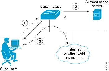
802.1X authentication involves the following three network devices:
- A supplicant : a client device (such as a laptop or endpoint) that attempts to access a LAN/Wireless LAN (WLAN), or the software that runs on this device and that provides credentials to the authenticator.
- An authenticator : a network device (such as an Ethernet switch or wireless access point) that acts as an access point to a protected network. For 802.1X authentication, the supplicant provides network credentials, such as user name, password, digital security certificate, or a combination of these, to the authenticator. The authenticator then forwards the credentials to the authentication server for verification.
• An authentication server : a server (such as Cisco Secure Access Control Server) that guards the protected network. For 802.1X authentication, the authentication server receives the supplicant’s network credentials from the authenticator and verifies the supplicant’s identity. Then the supplicant is able to access the resources located on the network.
Figure 4-4 Diagram of 802.1X Authentication Process
Authenticating Your System
Your Cisco TelePresence System is equipped to function as an 802.1X-compliant supplicant. 802.1X authentication is enabled by default.
Note Cisco recommends that you configure your switch port (or authenticator) for multi-domain mode.
Setting up 802.1X Authentication
This section describes the steps you perform to set up 802.1x authentication, and includes the following topics:
- Authenticating the Cisco TelePresence System Using a Security Certificate (MIC or LSC)
- Examining the Security Certificate in the Cisco TelePresence System
Note In order to complete 802.1X authentication, you must use a port that is not already enabled for 802.1X.
Authenticating the Cisco TelePresence System Using a Security Certificate (MIC or LSC)
When the Cisco TelePresence System receives an authentication challenge from an Authenticator, the system responds with either the Manufacturing Installed Certificate (MIC) or the Locally Significant Certificate (LSC). When both the MIC and LSC are installed, the system uses the LSC to authenticate. If the LSC is not installed, Cisco TelePresence System uses the MIC, as the MIC is built into the system by the manufacturer.
The LSC provides greater security because it creates a public key infrastructure (PKI) that is unique to each system. To authenticate the codec using the LSC, you must install it on your system manually by using the Certificate Authority Proxy Function (CAPF) in Cisco Unified Communication Manager (CUCM). For more information, see the “Installing the LSC” section.
Installing the LSC
To install the LSC, refer to the “Deploying Locally Significant Certificates” section found in the IP Telephony for 802.1X Design Guide .
Examining the Security Certificate in the Cisco TelePresence System
You may want to examine the security certificate (MIC or LSC) on an 802.1X-authenticated system in order to verify that the certificates are valid, not expired, and issued by the CAPF.
To examine the security certificate in your Cisco TelePresence System, you may download a copy of the certificate to your own system by using either of two methods:
Downloading the Security Certificate Using the CLI
To download the MIC or LSC using the CLI, complete the following steps:
Step 2![]() Enter the following command:
file get cert
{
cert-type
} {
SCP-user
} {
SCP-password
} {
IP-address-or-hostname
} {
file-save-location
}
Enter the following command:
file get cert
{
cert-type
} {
SCP-user
} {
SCP-password
} {
IP-address-or-hostname
} {
file-save-location
}
See Table 4-9 for syntax descriptions.
After entering the command, the security certificate will save on the target system in the designated file-save location:
If you select the LSC as the type of certificate to retrieve, but the LSC is not installed on the Cisco TelePresence System, the command line will read as follows:
Executed command unsuccessfully
If the LSC command is unsuccessful, you need to install the LSC on the codec. See the “Installing the LSC” section. If the command is successful, continue to the next step.
Step 3![]() Go to the designated file-save location, and click the file to view the certificate.
Go to the designated file-save location, and click the file to view the certificate.
Downloading the Security Certificate Using the GUI
To download the MIC/LSC from the GUI, complete the following steps:
Step 1![]() Log into the GUI and navigate to
Configuration > Security Settings.
Log into the GUI and navigate to
Configuration > Security Settings.
Step 2![]() Click
Download
to download and view a certificate. A dimmed Download button indicates the lack of a given certificate.
Click
Download
to download and view a certificate. A dimmed Download button indicates the lack of a given certificate.
Checking the CTS 802.1x Authentication Status
To check 802.1X authentication status in the Cisco TelePresence System, use either of the following options:
- View the CTS primary display screen during system bootup (see the “Checking the 802.1X Authentication Status on the Primary Display Screen” section)
- Enter the CLI command show dot1x status (see the “Checking the 802.1X Authentication Status with a CLI Command” section)
Checking the 802.1X Authentication Status on the Primary Display Screen
To check the 802.1X authentication status on the Cisco TelePresence System primary display screen, complete the following steps:
Step 1![]() Power off the Cisco TelePresence System.
Power off the Cisco TelePresence System.
Step 2![]() Power on the Cisco TelePresence System.
Power on the Cisco TelePresence System.
Step 3![]() View the bottom right of the primary display screen. In a three-screen system, view the bottom-right of the center screen. Text will display to indicate whether 802.1X is authenticated, not authenticated, or not required on your system.
View the bottom right of the primary display screen. In a three-screen system, view the bottom-right of the center screen. Text will display to indicate whether 802.1X is authenticated, not authenticated, or not required on your system.
This text, as viewed on the Cisco TelePresence System primary display screen, indicates the success or failure of 802.1X authentication on that system. If the status line reads “Not Required,” 802.1X authentication is not required for that system.
Figure 4-5 Screenshot of Cisco TelePresence System Boot-Up Screen
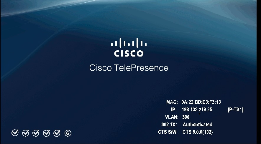
See Table 4-10 for a summary of 802.1X authentication status displays for enabled and non-enabled networks.
Note The 802.1X authentication status can only be viewed on your Cisco TelePresence System primary screen, not on a secondary screen (e.g., a presentation screen, or in a three-screen system, the left or right screen). If the 802.1X authentication status does not show on the primary screen, follow the steps below listed under the “Checking the 802.1X Authentication Status with a CLI Command” section
Checking the 802.1X Authentication Status with a CLI Command
To check the 802.1X authentication status with a CLI command, complete the following steps:
Step 2![]() Input the following command:
show dot1x status
Input the following command:
show dot1x status
Step 3![]() View resulting text. Text will display indicating whether 802.1X is authenticated, not authenticated, or not required on your system.
View resulting text. Text will display indicating whether 802.1X is authenticated, not authenticated, or not required on your system.
Troubleshooting 802.1x Authentication Issues
When 802.1X does not authenticate properly, review the following sections:
Troubleshooting Issues in 802.1X Authentication
Table 4-11 summarizes some issues that may appear during 802.1X authentication, as well as potential resolutions.
Cisco Secure ACS authentication server rejects security certificate from the Cisco TelePresence System supplicant. |
The security certificate is invalid, expired, or not issued by CAPF. |
Install a valid, non-expired security certificate using the CAPF. See Viewing the Security Certificate. |
Errors may be present in the system’s most recent log files. |
Use the file list log dot1x command in the CLI to check logs for error or failure messages. |
|
Cisco TelePresence System displays “802.1X: Not Required” on its boot-up screen. |
Check the 802.1X authentication status on the ethernet switch by logging into the switch and using the CLI command show authentication sessions interface { FastEthernet | GigabitEthernet } { Interface Number }. If the ethernet switch is not 802.1X-enabled, enable it. Please refer to Identity-Based Networking Services: IP Telephony in IEEE 802.1X-Enabled Networks Deployment and Configuration Guide for instructions. |
|
Cisco Secure ACS authentication server rejects security certificate from the Cisco TelePresence System supplicant. |
Configure Cisco Secure ACS (and all backend network configurations) to support 802.1X. Please refer to Identity-Based Networking Services: IP Telephony in IEEE 802.1X-Enabled Networks Deployment and Configuration Guide for instructions. |
|
Cisco TelePresence System attempts authentication with the MIC instead of the LSC. |
The LSC has not been exported from CAPF and imported into Cisco Secure ACS. |
Check that the LSC is exported from CAPF and imported into Cisco Secure ACS. See Installing the LSC. |
After moving to a different CAPF and Unified CM, Cisco TelePresence System fails 802.1X authentication. |
The LSC no longer supports 802.1X authentication, since it was installed from the previous CAPF and Unified CM. Moving the Cisco TelePresence System to a different CAPF and Unified CM requires reinstalling the LSC and upgrading the system. |
Reinstall the LSC from Cisco Unified CM and upgrade the Cisco TelePresence System. See Installing the LSC. |
Viewing the Security Certificate
You may need to examine the security certificate (MIC or LSC) in order to verify that the certificates are valid, not expired, and issued by the CAPF.
You can use the CLI or a third-party tool to view the MIC or LSC.
Viewing the Security Certificate from the CLI
To show the MIC or LSC from the CLI, complete the following steps:
Step 2![]() Enter the following command:
show cert
{
mic
|
lsc
}. You must enter either
mic
or
lsc
, not both.
Enter the following command:
show cert
{
mic
|
lsc
}. You must enter either
mic
or
lsc
, not both.
Step 3![]() View the certificate that displays within the CLI. Verify that the certificate is valid, not expired, and issued by the CAPF.
View the certificate that displays within the CLI. Verify that the certificate is valid, not expired, and issued by the CAPF.
Subject: C=US, O=organization, OU=department, CN=SEPXXXXXXXXXXXX
If you enter show cert lsc on a system where the LSC is not installed, the command line will read as follows:
If the security certificate is expired, invalid, or issued by a different source, install a new certificate using the CAPF.
Adjusting the White Balance for Your System
To adjust the white balance settings for your cameras, complete the following steps.
Step 1![]() Prepare the camera targets for the white balance by completing the following actions:
Prepare the camera targets for the white balance by completing the following actions:
Note If you need to order a camera target kit, including the mounting hardware for the target, order CTS-CAM-TOOL= for the Cisco TelePresence System TX9000 and TX9200, and CTS-CAM-TOOL-G2= for the Cisco TelePresence TX1310 65 or Cisco TelePresence TX1300 47.
- If your system is a Cisco TelePresence System TX9000 or Cisco TelePresence System TX9200, prepare your camera targets by completing the following steps:
a.![]() Assemble the large camera target, using Figure 4-6 as a guide.
Assemble the large camera target, using Figure 4-6 as a guide.
When you slide the Camera target into the frame, make sure the target is centered in the frame between the vertical lines at the top and bottom of the target.
Figure 4-6 Camera Target Assembly

b.![]() Attach the large target to the underside of the left table section by placing the round pads on the underside of the clamps into recesses that are drilled under the table, with the white part of the target facing the camera.
Attach the large target to the underside of the left table section by placing the round pads on the underside of the clamps into recesses that are drilled under the table, with the white part of the target facing the camera.
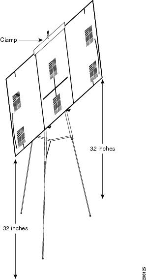
- If your system is a Cisco TelePresence TX1310 65 or Cisco TelePresence TX1300 47, prepare your camera targets by performing the following actions:
a.![]() Remove the easel, large camera target, and small camera target from their packaging.
Remove the easel, large camera target, and small camera target from their packaging.
b.![]() Unlock and slide the telescoping legs of the easel until the legs are at their full height.
Unlock and slide the telescoping legs of the easel until the legs are at their full height.
d.![]() Raise the front legs until they are 29 inches (74 cm) high.
Raise the front legs until they are 29 inches (74 cm) high.
e.![]() Raise the rear leg until it is 31 inches (79 cm) high.
Raise the rear leg until it is 31 inches (79 cm) high.
f.![]() Lock the legs into place using the leg locks.
Lock the legs into place using the leg locks.
g.![]() Attach the large camera target to the clip on top of the easel.
Attach the large camera target to the clip on top of the easel.
h.![]() Raise the target supports on the front legs until they touch the lower part of the large camera target.
Raise the target supports on the front legs until they touch the lower part of the large camera target.
i.![]() Raise and lower the front legs until the bottom of the camera target is 32 inches (81 cm) above the ground.
Raise and lower the front legs until the bottom of the camera target is 32 inches (81 cm) above the ground.
j.![]() Place the camera target and easel behind the left camera segment.
Place the camera target and easel behind the left camera segment.
Figure 4-7 Easel and Target After Assembly
Step 2![]() Using a supported browser, log in to the Cisco TelePresence Administration GUI for your system.
Using a supported browser, log in to the Cisco TelePresence Administration GUI for your system.
Step 3![]() Navigate to
Troubleshooting > Hardware Setup
and click the
Cameras
radio button.
Navigate to
Troubleshooting > Hardware Setup
and click the
Cameras
radio button.
Step 4![]() Click
Start
in the Testing area.
Click
Start
in the Testing area.
Note Make sure that the left camera shows only the target. If other parts of the room can be seen, reposition the target.
Step 5![]() Click the
Setup
button underneath the left display in the GUI.
Click the
Setup
button underneath the left display in the GUI.
The auto adjust procedure automatically adjusts the white balance for your system.
Step 7![]() Click
Close
to close the Auto Adjust pop-up window.
Click
Close
to close the Auto Adjust pop-up window.
Step 9![]() Position the target for the center segment.
Position the target for the center segment.
Step 10![]() Click the
Setup
button underneath the center display and click
Auto Adjust
.
Click the
Setup
button underneath the center display and click
Auto Adjust
.
The auto adjust procedure automatically adjusts the white balance for your system.
Step 11![]() Click
Close
to close the Auto Adjust pop-up window, then click
Done
.
Click
Close
to close the Auto Adjust pop-up window, then click
Done
.
Step 12![]() Position the target for the right segment.
Position the target for the right segment.
Step 13![]() Complete Step 10 and Step 11, substituting the right segment for the center segment.
Complete Step 10 and Step 11, substituting the right segment for the center segment.
Step 14![]() Click
Stop
to stop the testing procedure.
Click
Stop
to stop the testing procedure.
 Feedback