Feedback
Table Of Contents
Synchronization and Timing Support
Network Synchronization
MGX 8230 Clock Sources
The clock sources that are available for primary and secondary clock selection are
•
Extracted received clock from the daughter card trunking interface (up to two ports)
•
–
–
•
•
Synchronization and Timing Support
The PXM1 supports either a Stratum 3 or Stratum 4 enhanced clock.
The internal clock meets the Stratum 3 and Stratum 4 requirements as detailed in Table 9-1 and Table 9-2.
Table 9-1 Stratum 3 Requirements
4.6xe-6
1xe-8/day
4.6xe-6
Table 9-2 Stratum 4 Requirements
32x10-6
no holdover
32x10-6
Internal Holdover Capability
The MGX 8230 guarantees an 8 kHz clock speed during the time it switches over to other sources.
The MGX 8230 clock synchronization system meets the following criteria as specified Bellcore GR-1244-CORE, Section 2.6
•
•
•
•
The MGX 8230 also supports clock synchronization system redundancy in compliance to GR-1244-CORE, Section 3.3.
External Timing Interfaces
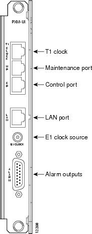
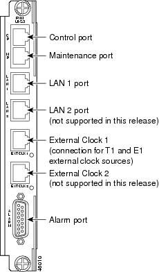
The MGX 8230 accepts external timing from T1 and E1 interfaces. The PXM User Interface card that resides in the upper service bay provides the T1/E1 timing reference ports:
•
•
Figure 9-1 PXM-UI Rear View
Figure 9-2 PXM-UI-S3 Rear View
E1 Interface Compliance
The E1 interface on the PXM back card has been designed to support both options according to G.703. As per G.703 Table 6, it supports an unframed HDB3 E1 (2048 KBps) signal. According to G.703 Table 10 (now calledTtable 11), it also supports a timing signal of 2048 kHz.
External Timing
MGX 8230 is capable of the following external timing and formats:
•
•
•
•
The MGX 8230 Edge Concentrator is capable of receiving a minimum of two external timing references on separate physical interfaces. These are provisioned as the active (act) and alternate (alt). The terms act and alt are interchangeable depending on which reference is active, and providing timing reference for the system. The system also provides a DS1 reference for external timing in D4 (SF) format. At least two DS1 synchronization references, as specified in Bellcore GR-1244-CORE, Section 3.4, can be configured.
A switchover from the active clock source (primary or secondary) to the standby clock source will occur when the hardware detects a failure that warrants a switchover. The currently selected clock source is constantly monitored by the hardware to ensure that it is within tolerance.
If a failure in this selected clock is detected, the hardware gracefully switches over to the secondary clock source specified.
If both the primary and secondary sources have failed, the hardware will automatically output the clock generated internally on the card. Once the primary clock is within tolerance, the hardware will automatically switch back to it.
Regardless of whether the clock switchover is initiated by the user or by the hardware, the switchover meets the Accunet T1.5 Maximum Time Interval Error (MTIE) Specification.
When all timing references fail, as specified in Bellcore GR-1244-CORE, Section 3.4.1, the MGX 8230 can operate in self-timing or free-running mode, using an internal clock.
Revertive Clocking
Clocking can be either revertive or non-revertive.
•
•
Whether a node is revertive or non-revertive depends upon the processor switching back card used and clocking source specified. Please refer to Table 9-3 to determine whether clocking is revertive or non-revertive in your network configuration.
Continuous Monitoring
The MGX 8230 recognizes the following DS1 impairments or conditions as failures:
•
•
•
•
Generating Alarms
Alarms are generated when a synchronization source, either active or standby, fails for some reason. Clocking failures do not affect any configuration or settings on either the PXM 1 or PXM45.
Software/Hardware Upgrades
Switch software upgrades do not cause changes in timing sources. A Y-cable is used to connect the external clock associated with both the active and standby processor cards. Part of the normal switch software upgrade process is a PXM switchover, the Y-cable will ensure clocking integrity to the external source.