Feedback
Table Of Contents
Physical Layer T3/E3 Interface
Physical Layer OC-3c/STM-1 Interface
Physical Layer OC-12c/STM-4 Interface
Processor Switch Module
Overview
The Processor Switch Module (PXM1) provides the switching fabric in the MGX 8230 chassis. This PXM1 allows Cisco customers to scale the switch focus and capacity to 1.2 GBps (PXM1). The PXM1 combines the functions of the processor, the switch fabric, and broadband ports into a single module.
The MGX 8230 supports both shared memory and cross-point switching technologies to optimize costs for narrowband requirements. Although the backplane is capable of 45 GBps, the customer can choose to deploy a 1.2 GBps-shared memory fabric (PXM1) to support the narrowband service modules. The PXM1 provides 1.2 GBps of nonblocking bandwidth.
PXM1 Switch Fabric Module
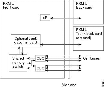
The switch fabric (PXM1) provides up to 1.2 GBps of nonblocking ATM switching along with an integrated hard disk for statistical and management features and an ATM multicast engine. Figure 3-1 shows the PXM1 architecture.
Figure 3-1 PXM1 Architecture
In addition to the switch processor and switch fabric, the PXM1 module also supports three types of trunking daughter cards, reducing the requirement for allocating additional slot positions for trunk modules. The PXM1 trunking daughter cards and associated back cards are intended to provide native ATM interfaces, which can be configured as either trunks or ports, but are cost-optimized for trunking. The PXM1 trunking back cards are available in the following physical interfaces:
•
2-port T3/E3 ATM
•
•
The PXM1 performs the following functions:
•
The PXM1 is responsible for monitoring and controlling the card modules.
•
The PXM1 houses the shared-memory switch that sends and receives ATM cells from the network trunk and service modules.
•
All ATM cells created by the service modules are sent to the PXM1 card to be switched to other service modules or the attached ATM network. The PXM1 is responsible for managing the flow of cells on the cell bus.
•
Network management devices, such as Cisco WAN Manger workstation, PC, and dumb terminal communicate directly with the PXM1
•
A copy of the configuration database and firmware image for each service module installed is stored on the PXM1 on a PCM-CIA disk drive.
•
The PXM1 is responsible for extracting a clock signal from either an external clock source or the trunk to the ATM network. The PXM1 propagates the timing signals across the switch's timing bus.
•
Chassis temperature and fan and power supply status are monitored by the PXM1.
•
Local major and minor alarms are reported by the PXM1 via front card LEDs and dry contact relays on the PXM1-UI back card.
The PXM1 and all the inputs (cell bus and trunk interfaces) support configuration for 1:1 hot-standby redundancy. Each PXM1 supports two active back cards, the upper level back card provides the BITS synchronization interfaces and the OAM interfaces while the lower back card provides the trunk interfaces. Both the active and redundant PXM1 are able to access either pair of the PXM1 back cards, which eliminates the necessity of a PXM1 switch-over if either of the back cards should fail. The
MGX 8230 midplane supports full OC-12c bandwidth to each trunk back card. The PXM1 trunk back cards also support cross-coupling between trunk interfaces for SONET APS 1+1 redundancy support.All local connections go through QE0 and each local connection consumes two GLCNs (one for each direction). QE0 supports 32K GLCNs so a total of 16K local connections can be supported in hardware.
From a hardware perspective the PXM1 can support up to 32K connections.
PXM1 Front Card Support
The following set of functionality is supported on the PXM1 front card:
•
•
•
•
PXM1 Back Card Support
PXM1 back cards provide high-speed (T3, OC-3, OC-12) native ATM interfaces that can be configured as ATM UNI ports or trunks. The interfaces are cost-optimized for trunking. Cross-coupling signals are provided between the lower back cards to allow Automatic Protection Switching (APS). The PXM1 supports two back cards. The upper card supports the following ports and interfaces.
•
–
–
–
•
–
–
–
•
–
–
–
–
The lower back card on PXM1 provide one of the following ATM interfaces:
•
•
•
The PXM1 back cards provide user accessible interfaces for the uplink trunks and for management and alarm interfaces.
PXM1-UI
The PXM1-UI back card provides user access to the following interfaces:
•
•
•
•
•
PXM-UI-S3 (optional)
The PXM-UI-S3 is an optional card that provides external Stratum 3 clocking. This back card provides user access to the following interfaces:
•
•
•
•
•
Uplink Back Cards
The uplink back cards provide line drivers for the uplink interface. The following interfaces are provided:
•
•
•
•
•
•
•
A mismatch between the uplink back card type and the PXM1 will generate a major alarm.
Table 3-1 lists the PXM1 modules. Table 3-2 provides the interface characteristics.
Bandwidth
The PXM1 provides 1.2 GBps of nonblocking bandwidth.
Cell Bus Access
The cell bus is a Poll-Request-Grant bus. The polling algorithm is based on round-robin servicing. The granting is based on a programmable rate factor for the device. For example, if a device (service module) has been guaranteed 45 Mbps bandwidth, whenever the grant rate of that device falls below the rate, the priority of the device will be increased until minimum rate is guaranteed.
The eight cell buses are grouped into two groups. Excess bandwidth is proportionally shared among all devices within the same group.
When the cell buses are running at double speed, each cell bus is guaranteed 160 Mbps bandwidth. The excess bandwidth is shared proportionally among all devices within the same group. Therefore it is important that one does not attempt to set the total guaranteed bandwidth for either the left side or right side of the chassis to be more than 640 Mbps.
Processor (IDT 4700)
The IDT 4700 processor module provides the following basic features:
•
•
•
•
•
Clocking Options
The PXM1 supports a minimum of two external timing references on separate physical interfaces. These are provisioned as the active (act) and alternate (alt). The terms act and alt are interchangeable depending on which reference is active, and providing timing reference for the system. The system also provides a DS1 reference for external timing in D4 (SF) format. At least two DS1 synchronization references, as specified in Bellcore GR-1244-CORE, Section 3.4, can be configured.
A switchover from the active clock source (primary or secondary) to the standby clock source will occur when the hardware detects a failure that warrants a switchover. The currently selected clock source is constantly monitored by the hardware to ensure that it is within tolerance.
If a failure in this selected clock is detected, the hardware gracefully switches over to the secondary clock source specified.
If both the primary and secondary sources have failed, the hardware will automatically output the clock generated internally on the card. Once the primary clock is within tolerance, the hardware will automatically switch back to it.
Regardless of whether the clock switchover is initiated by the user or by the hardware, the switchover meets the Accunet T1.5 Maximum Time Interval Error (MTIE) specification.
When all timing references fail, as specified in Bellcore GR-1244-CORE, Section 3.4.1, the MGX 8230 can operate in self-timing, or free-running mode, using an internal clock.
Interfaces
The user interface back card features are as follows.
•
•
–
–
–
–
–
•
System Environment Monitoring
The following system environmental parameters are monitored and logged by the PXM1:
•
•
•
•
Minor and major alarms will be generated when one or more environmental parameters are out of range.
Alarm Circuit and Indicators
PXM1 provides connectors for external audio and visual alarms. The PXM1 monitors ACO and History push-buttons located in its front card faceplate. It controls the following LEDs, which are also located on the PXM1 front card faceplate:
•
–
–
–
•
–
•
–
–
•
–
–
•
–
–
•
–
–
–
–
Figure 3-2 shows the PXM1 LEDs.
Figure 3-2 PXM1 LEDs
PXM1 provides three types of nonvolatile storage:
•
•
•
–
–
–
The BRAM also acts as a temporary cache. If for any reason the hard drive fails, log information immediately before the failure can be stored in the BRAM for further analysis.
Optical Interfaces
As the optical transceivers in the PXM1 interfaces are ITU-T G.957 compiant, G.957 dispersion tolerances are:
•
Maximum dispersion in the optical path is 96 ps/nm
•
Maximum dispersion in the optical path is 185 ps/nm
•
Maximum dispersion in the optical path is 74 ps/nm
•
Maximum dispersion in the optical path is 109 ps/nm
The modulation used in all PXM1 optics is direct built-in electroabsortion modulator in standard temperature range (0-70°C). The type of laser sources for the different PXM1 interfaces are
•
•
•
•
Physical Layer T3/E3 Interface
The T3/E3 interface provides
•
•
•
•
Physical Layer OC-3c/STM-1 Interface
The OC-3c/STM-1 interface provides
•
•
•
•
•
•
•
•
Physical Layer OC-12c/STM-4 Interface
The OC-12c/STM-4 interface provides:
•
•
•
•
•
•
ATM Layer
The ATM layer is configurable for trunk and public or private UNI applications. It is conformant to ATM Forum UNI Specification V3.0, 3.1, ITU-T I.361 and I.432 specifications, and it supports virtual circuit connections (VCCs) and virtual path connections (VPCs) per ATM Forum UNI Specification V3.1 and ITU-T I.371.