Feedback
Table Of Contents
Node Management (Control Point) Software
Software Architecture
Overview
The software on the MGX 8230 is comprised of three major functional blocks:
•
Platform control
•
•
To deliver these services, the software is partitioned into four main software areas.
1.
2.
3.
4.
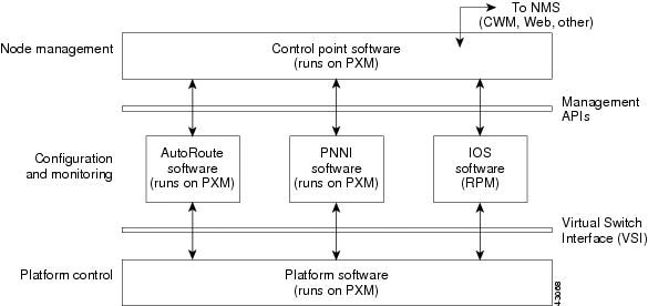
In addition, the Virtual Switch Interface (VSI) provides a single controller implementation that can be used across different platforms for the same function; and management APIs provide an interface between the network control modules and node management software.
Figure 5-1 provides an overview of the MGX 8230 software architecture and the relationships of the software modules to other components.
Figure 5-1 MGX 8230 Software Architecture
Platform Software
The platform software is responsible for the low-level operation of the system (including resource management and physical redundancy control). This layer provides a set of services to the remaining subsystems. These services are categorized as Generic Cross-Connection Service, Basic Platform-Specific Configuration and Monitoring Service, and Platform Infrastructure.
1.
The platform software contains the Virtual Switch Interface (VSI) API to provide a generic set of cross-connect control services for setting up and tearing down single-hop cross-connects. The VSI service provides the means for network control subsystems to:
–
–
–
2.
The platform software provides an API to the management layer (for example, the Control Point software) to allow the configuration and monitoring of cards, ports, redundancy options, and any platform-specific features. It also enables the platform software to generate asynchronous events to the management layer. This API consists of a message passing request/response protocol running on the PXM.
3.
The platform software provides the basic infrastructure for the following features.
–
–
–
–
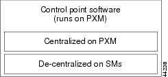
As shown in the Figure 5-2, the platform software has a centralized component running on the PXM, and distributed code running on the service modules.
Figure 5-2 Platform Software Components
Distributed Processing
The MGX 8230 platform software is based on a distributed processing model. The MGX 8230 Inter-Processor Communication, built upon Remote Procedure Call (RPC) and the Shelf Communication Module (SCM) paradigm, allows clients to make remote procedure calls through a local procedure call interface.
The MGX 8230 platform databases (MIBs) are also distributed among PXM, RPM, and the service modules. For example, the line, port, and channel databases are maintained by the individual service module and the connection database is maintained by PXM.
VSI
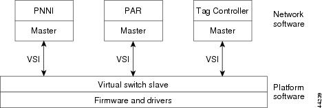
To interface with multiple network software controller types, a standardized interface was created known as the Virtual Switch Interface (VSI) (see Figure 5-3). VSI defines the messages and associated functions that allow communication between the controller and the switch software.
Originally designed for PNNI portability between platforms, the VSI enables a single controller implementation that can be used across different platforms for the same function. For example, a single PNNI controller developed for the MGX 8230 could be used on the BPX 8600.
Furthermore, by having a common messaging interface, the controllers do not have to reside on the same card or box. The Label Switch Controller (LSC) on the MGX 8230 resides on the RPM card as opposed to Portable Autoroute Controller, which resides on the PXM. Similarly, the Label Switch Controller, on Cisco 7500 and Cisco 7200 series routers, communicates using VSI to an external BPX's switch software.
Hence, VSI allows multiple services to run on the same platform. Each network software controller is a VSI master that talks to the VSI slave residing on the platform software.
Figure 5-3 Virtual Switch Interface (VSI)
Networking Control Software
There are three types of Network Controllers available on the MGX 8230. Only the Portable Autoroute Controller is currently available.
1.
The three network controllers include:
a.
b.
Portable AutoRoute
Portable AutoRoute (PAR) performs the following functions:
•
•
•
•
Cisco IOS Routing Subsystem
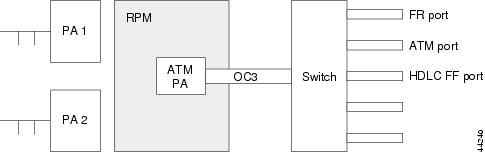
The Cisco IOS software, running on one or more RPMs, provides Layer 3 services for the shelf. The management software presents the MGX 8230 as a fully integrated component. The Cisco IOS subsystem also has two APIs as illustrated in Figure 5-4.
Figure 5-4 RPM View of the PXM
Node Management (Control Point) Software
The node management software (or Control Point software) resides on the PXM. It provides a single, integrated point of control for managing the platform. It provides full shelf and interface management for all hardware modules, service provisioning, and fault finding/diagnostic support for the complete shelf.
The MGX 8230 components that are managed with the Control Point software include:
•
•
•
•
SNMP Support
The SNMP-based message interface is used between the front end and agents. The interface between the agents and the MIB functions is a direct function call or remote procedure calls depending upon the location of those two entities.
Command Line Interface
Control Point software presents a uniform management view of multiple products and technologies. The Command Line Interface (CLI) provides a single, integrated point of control for managing the MGX 8230 platform. It performs full-shelf and interface management for all hardware modules, service provisioning, and fault finding/diagnostic support for the complete shelf. The CLI provides:
•
•
•
•
The MGX 8230 provides the following CLI features:
•
•
•
•
•
•
Alarms and Traps
All alarms and events generate traps. MGX 8230 switches send traps to all registered trap managers when error events occur.
The Robust Trap Management (RTM) scheme is supported for PXM and all MGX 8230 service modules. RTM is a mechanism for keeping track of trap sequence numbers in traps so that the management system can provide complete trap information. Under this scheme, traps look like normal SNMP traps but have sequence numbers. If a missing sequence is detected, the network manager can request the missing trap.
Event Logging
Applications may log specific events and error conditions using the event mechanism provided by the platform software.
Statistics Registry
The MGX 8230 maintains a statistics subsystem primarily to monitor traffic conditions within the system. The TFTP daemon that handles configuration upload requests also services the statistics upload requests.
The statistics subsystem uses two levels of abstraction when gathering data: Files and Buckets. Each file contains one or more buckets. User activates the statistics manager on CWM, and selects the bucket interval and the collection period (both exprssed in minutes).
The Statistics Task runs periodically, building a new output file at the end of each collection period. The output files are used in a round-robin scheme, meaning that the file with the oldest data is always used next. The CWM system can request any of the files, using the time of day as a file index.
There is a fixed amount of memory reserved for statistics files. The number of files available depends on the file size.