Feedback
Table Of Contents
Frame Relay Service Modules (FRSM)
ATM UNI Service Modules (AUSM)
Circuit Emulation Service Modules (CESM)
Summary of FRSM Features By Module Version
Frame Relay Service Module Special Features
CESM-8T1/E1 Peak Cell Rate Calculation
Asychronous Clocking (Adaptive)
CESM-T3/E3 Peak Cell Rate Calculation
Electrical and Safety Standards
Multiple Groups of 1:N Redundancy
SM Redundancy with Line Modules
Bulk Mode Distribution/Redundancy
Frame Aggregation: Port Forwarding
ATM Deluxe Integrated Port Adapter/Interface
Service Modules
The MGX 8230 switch supports Frame Relay, CE, ATM, Cisco IOS (including IP services), and voice services through an array of service modules.
This chapter includes a summary of the available modules, followed by detailed information on the modules and the services they provide:
•
ATM Deluxe Integrated Port Adapter/Interface
Summary of Modules
The MGX 8230 supports the following service modules.
Service Resource Module (SRM)
Service Resource Module (MGX-SRM-3T3/C)
The optional SRM provides three major functions for service modules; bit error rate tester (BERT) of T1 and E1 lines and ports, loops back of individual N x 64 channels toward the customer premises equipment (CPE), and 1:N redundancy for the service modules.Frame Relay Service Modules (FRSM)
A variety of Frame Service Modules are supported as described in the following list.
•
The AX-FRSM-8T1 provides interfaces for up to eight fractional T1 lines, each of which can support one 56 kbps or one Nx64 kbps FR-UNI, FR-NNI port, ATM-FUNI, or a Frame forwarding port. The AX-FRSM-8T1 supports fractional and unchannelized T1 port selection on a per-T1 basis.•
The AX-FRSM-8E1 provides interfaces for up to eight fractional E1 lines, each of which can support one 56 kbps or one Nx64 kbps FR-UNI, FR-NNI, ATM-FUNI, or Frame forwarding port. The AX-FRSM-8E1 supports fractional and unchannelized E1 port selection on a per-E1 basis.•
The AX-FRSM-8T1-C allows full DS0 and n x DS0 channelization of the T1s. Each interface is configurable as up to 24 ports running at full line rate, at 56 or n x 64 kbps for a maximum of 192 ports per FRSM-8T1-C.•
The AX-FRSM-8E1-C allows full DS0 and n x DS0 channelization of the E1s. Each interface is configurable as up to 31 ports running at full line rate, at 56 or n x 64 kbps for a maximum of 248 ports per FRSM-8E1-C.•
The MGX-FRSM-2E3/T3 provides interfaces for two T3 or E3 Frame Relay lines, each of which can support either two T3 lines (each at 44.736 Mbps) or two E3 lines (each at 34.368Mbps) FR-UNI, ATM-FUNI, or Frame Forwarding port.•
The MGX-FRSM-2CT3 supports interfaces for two T3 channelized Frame Relay lines. Each interface supports 56 Kbps, 64 Kbps, Nx56 Kbps, Nx64 Kbps, T1 ports that can be freely distributed across the two T3 lines.•
The FRSM-HS1/B supports the 12-in-1 back card. This back card supports up to four V.35 or X.25 serial interfaces. This card also supports the two port HSSI back cards with SCSI-2 connectors.•
The MGX-FRSM-HS2/B supports interfaces for two unchannelized HSSI lines. Each interface supports approximately 51 Mbps; with both lines operating, maximum throughput is 70 Mbps.ATM UNI Service Modules (AUSM)
Two ATM UNI Service Modules are supported.
•
The MGX-AUSM/B-8T1 provides interfaces for up to eight T1 lines. You can group N x T1 lines to form a single, logical interface (IMA).•
The MGX-AUSM/B-8E1 provides interfaces for up to eight E1 lines. You can group N x T1 lines to form a single, logical interface (IMA).Circuit Emulation Service Modules (CESM)
Three Circuit Emulation Service Modules are supported.
•
The AX-CESM-8T1 provides interfaces for up to eight T1 lines, each of which is a 1.544 Mbps structured or unstructured synchronous data stream.•
The AX-CESM-8E1 provides interfaces for up to eight E1 lines, each of which is a 2.048-Mbps structured or unstructured synchronous data stream.•
The MGX-CESM-T3E3 provides direct connectivity to one T3 or E3 line for full-duplex communications at the DS3 rate of 44.736 MHz or at the E3 rate of 34.368 MHz. Each T3 or E3 line consists of a pair of 75-ohm BNC coaxial connectors, one for transmit data and one for receive data, along with three LED indicators for line status.Voice Service Modules (VISM)
MGX-VISM-8T1 and MGX-VISM-8E1
These cards support eight T1 or E1ports for transporting digitized voice signals across a packet network. The VISM provides toll-quality voice, fax and modem transmission and efficient utilization of wide-area bandwidth through industry standard implementations of echo cancellation, voice-compression and silence- suppression techniques.
Note
Route Processor Module (RPM)
Route Processor Module (RPM)
The RPM is a Cisco 7200 series router redesigned as a double-height card. Each RPM uses two single-height back cards. The back card types are single-port Fast Ethernet, four-port Ethernet, and single-port (FDDI).
Note
Note
Frame Relay Services
The primary function of the Frame Relay Service Modules (FRSM) is to convert between the Frame Relay formatted data and ATM/AAL5 cell-formatted data. For an individual connection, you can configure network interworking (NIW), service interworking (SIW), ATM-to-Frame Relay UNI (FUNI), or frame forwarding.
Summary of FRSM Features By Module Version
Table 4-1 summarizes the basic features of the Frame Relay service modules for the MGX 8230.
Features Common to All FRSMs
The features supported by all FRSM cards are
•
•
•
•
•
•
•
Frame Relay Service Module Special Features
The following special features are supported by all FRSM cards:
•
•
•
•
•
•
•
•
Circuit Emulation Services
The CE service module (CESM) use a standards-based adaptation of circuit interfaces onto ATM.
CE Service Modules
Table 4-2 summarizes the key attributes of the CE service modules.
CESM-8T1/E1 Features
The CESM-8T1/E1 features are listed below.
•
•
•
•
•
•
•
–
–
–
–
–
•
CESM-8T1/E1 Peak Cell Rate Calculation
The following features are shared by all CE service modules:
•
•
•
–
–
•
–
–
•
–
–
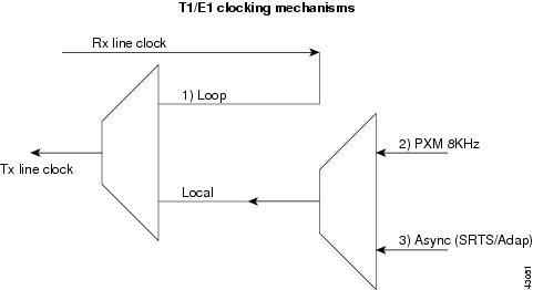
T1/E1 Clocking Mechanism
The CESM card provides the choice of physical interface Tx clock from one of the following sources, (see Figure 4-1):
1.
2.
3.
Figure 4-1 T1/E1 Clocking Mechanisms
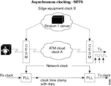
Asynchronous Clocking (SRTS)
Synchronous Residual Time Stamp (SRTS) clocking requires a Primary Reference Source (PRS) and network clock synchronization services. This mode allows user equipment at the edges of an ATM network to use a clocking signal that is different (and completely independent) from the clocking signal being used in the ATM network. However, SRTS clocking can only be used for unstructured (clear channel) CES services.
For example, in Figure 4-2, user equipment at the edges of the network can be driven by clock B, while the devices within the ATM network are being driven by clock A. The user-end device introduces traffic into the ATM network according to clock B. The CESM segments the CBR bit stream into ATM cells; it measures the difference between user clock B, which drives it, and network clock A. This delta value is incorporated into every eighth cell. As the destination CESM receives the cells, the card not only reassembles the ATM cells into the original CBR bit stream, but also reconciles the user clock B timing signal from the delta value. Thus, during SRTS clocking, CBR traffic is synchronized between the ingress side of the CES circuit and the egress side of the circuit according to user clock signal B, while the ATM network continues to function according to clock A.
Figure 4-2 Asynchronous Clocking
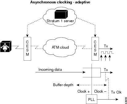
Asychronous Clocking (Adaptive)
Adaptive clocking requires neither the network clock synchronization services nor a global PRS for effective handling of CBR traffic. Rather than using a clocking signal to convey CBR traffic through an ATM network, adaptive clocking infers appropriate timing for data transport by calculating an average data rate for the CBR traffic. However, as in the case with SRTS clocking, adaptive clocking can be used only for unstructured (clear channel) CES services. (See Figure 4-3).
For example, if CBR data is arriving at a CES module at a rate of X bits per second, then that rate is used, in effect, to govern the flow of the CBR data through the network. What happens behind the scenes, however, is that the CES module automatically calculates the average data rate. This calculation occurs dynamically as user data traverses the network.
When the CES module senses that its segmentation and reassembly (SAR) buffer is filling up, it increases the rate of the (TX) clock for its output port, thereby draining the buffer at a rate that is consistent with the rate of data arrival.
Similarly, the CES module slows down the transmit clock of its output port if it senses that the buffer is being drained faster than the CBR data is being received. Adaptive clocking attempts to minimize wide excursions in SAR buffer loading, while at the same time providing an effective means of propagating CBR traffic through the network.
Relative to other clocking modes, implementing adaptive clocking is simple and straightforward. It does not require network clock synchronization services, a PRS, or the advance planning typically associated with developing a logical network timing map. However, adaptive clocking does not support structured CES services, and it exhibits relatively high wander characteristics.
Figure 4-3 Asychronous Clocking (Adaptive)
CESM Idle Suppression
The CESM T1/E1 card in structured mode can interprets CAS robbed bit signaling for T1 (ABCD for ESF and AB for SF frames) and CAS for E1 (timeslot 16). The ABCD code is user configurable per VC (xcnfchan onhkcd = 0-15; ABCD = 0000 = 0 ... ABCD = 1111 = 15). By detecting on-hook/off-hook states, AAL1 cell transmission is suppressed for the idle channel; thereby reducing backbone bandwidth consumed. ON/OFF hook detection/suppression can be enabled/disabled per VC and ON/OFF hook states can be forced via SNMP through the NMS.
On the ingress end, the CESM card monitors the signaling bits of the AAL1 cell. Whenever a particular connection goes on-hook and off-hook, the CESM card senses this condition by comparing ABCD bits in the cell with pre programmed idle ABCD code for that channel.
When an on-hook state is detected, keep-alive cells are sent once every second to the far-end CESM. This prevents the far end from reporting an under-run trap during idle suppression, since no cells are transmitted. When the timeslot switches to off-hook mode, the CESM stops sending the keep-alive cells.
CESM-T3/E3 Specific Features
The specific features for the CESM-T3/E3 are
•
•
•
•
CESM-T3/E3 Peak Cell Rate Calculation
The CESM-T3/E3 peak cell rate calculations are as follows:
•
–
–
–
•
–
–
T3/E3 Clocking Mechanisms
The T3/E3 clock configuration is shown in Figure 4-4.
Figure 4-4 T3/E3 Clocking Mechanisms
The CESM card provides the choice of physical interface Tx clock from one of the following sources:
1.
2.
ATM Service
The ATM UNI Service Modules (AUSM/Bs) provide native ATM UNI (compliant with ATM Forum Version3.0 and Version3.1) interfaces at T1 and E1 speeds, with eight ports per card, providing up to 16 Mbps of bandwidth for ATM service interfaces.
Consistent with Cisco's Intelligent QoS Management features, AUSM/B cards support per-VC queuing on ingress and multiple Class-of-Service queues on egress. AUSM/B cards fully support continuous bit rate (CBR), variable bit rate (VBR), unspecified bit rate (UBR), and available bit rate (ABR) service classes.
The AUSM/B-8 cards also support ATM Forum-compliant inverse multiplexing for ATM (IMA). This capability enables multiple T1 or E1 lines to be grouped into a single high-speed ATM port. This N x T1 and N x E1 capability fills the gap between T1/E1 and T3/E3, providing bandwidth up to 12 Mbps (N x T1) or 16 Mbps (N x E1) without requiring a T3/E3 circuit.
A single AUSM/B card can provide hot-standby redundancy for all active AUSM/B cards of the same type in the shelf (1:N redundancy).
AUSM/B modules are supported by standards-based management tools, including SNMP, TFTP (for configuration and statistics collection), and a command line interface. The Cisco WAN Manager application suite also provides full graphical user interface support for connection management, and CiscoView software provides equipment management.
Table 4-3 summarizes the key attributes of the AUSM/B cards.
AUSM/B Key Features
The key features of the AUSM/B card are as follows.
•
•
•
•
•
–
–
–
•
•
•
•
•
•
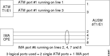
AUSM/B Ports
On the AUSM/B card, the term "port" is used to collectively refer to two types of logical interfaces: ATM T1/E1 ports and IMA groups. ATM ports are defined on a T1 or E1 line and one port is mapped to one line. IMA groups are composed of a logical grouping of lines defined by the user.
In total, the AUSM/B-8T1/E1 can support a maximum of eight logical ports (see Figure 4-5), of which some can be ATM T1/E1 ports and some can be IMA ports. An ATM T1/E1 port numbered i precludes the possibility of an IMA port numbered i. These logical port numbers are assigned by the user as part of configuration. The term IMA group and IMA port will be used synonymously.
The bandwidth of the logical port or IMA group is equal to:
(number of links) * (T1/E1 speed - overhead of IMA protocol)
Figure 4-5 AUSM/B Ports
AUSM/B-IMA
IMA offers the user a smooth migration from T1/E1 bandwidth to n * T1/E1 bandwidth without having to use a T3/E3. Multiple T1/E1 lines form a logical pipe called the IMA group.
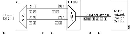
The IMA group is based on cell-based inverse multiplexing, whereby the stream of incoming cells are distributed over multiple T1/E1 lines (sometimes referred to as links) on a per-cell basis in a cyclic round-robin manner (see Figure 4-6). On the far end, the cells are recombined and the original stream is recreated. From the perspective of the application and the rest of the network, the inverse multiplexing function is transparent and the IMA group is viewed as any other logical port.
T1/E1 lines routed through different path (different carrier) are supported within the same IMA group. The ingress end compensates for the differential delay among individual links in an IMA group.
The maximum link differential delay is 275msec for T1 and 200 for E1.
Within an IMA group, each line is monitored and lines with persistent errors are taken out of data round-robin. The link is activated again when it is clear of errors at both ends.
The connectivity test procedure allows the detection of mis-connectivity of links. A test pattern is sent on one link of the IMA group. The Far End (FE) IMA group loops back the test pattern on all links in the group.
Figure 4-6 AUSM/B-IMA Ports
IMA Protocol
IMA protocol is based on IMA framing. An IMA frame is defined as M consecutive number of cells transmitted on each link in an IMA group. The ATM Forum requires the IMA implementation to support M=128 cells and optionally support M=32, 64, and 256. The current AUSM/B implementation only supports frame lengths of 128 cells. The transmitting IMA aligns the transmission of IMA frames on all links within the group.
The IMA protocol uses two types of control cells: IMA Control Protocol (ICP) cells and Filler Cells.
•
•
ICP and Filler cells have VPI=0, VCI=0, PTI=5, and CLP=1.
AUSM/B IMA Features
IMA allows for diverse routing of T1/E1 lines in the IMA group. The ingress end of the IMA port compensates for differential delay among the lines within a set limit. The maximum configurable delay for a T1 is 275 ms and the maximum configurable delay for an E1 is 200 ms.
The IMA group also provides for a level of resiliency. The user can configure a minimum number of links that must be active in order for the IMA group to be active. This allows the IMA group to still carry data traffic even during line failures (errors, signal loss) as long as the number of lines active does not fall below the user-configured value of the minimum number of links.
Manual line deletion and addition to an IMA group can be performed without any data loss. If the user is planning on eventually creating an IMA group, configure the line as an IMA group since future additions and deletions to an existing group are non-service disrupting.
Lines that experience bit errors are detected and are automatically removed if the errors are persistent. The threshold for line removal is not user configurable and is set at two consecutively errored IMA frames on a line. The line will automatically be added back in when frame synchronization is recovered.
The AUSM/B supports only Common Transmit Clock (CTC) mode of operation, whereby the same clock is used for all links in IMA group.
The IMA implemented on the AUSM/B is compliant with the ATM Forum IMA 1.0 Specification. ATM Forum-compliant IMA 1.0 interoperability testing has been conducted with the Cisco 2600/3600, ADC Kentrox AAC-3, Larscom NetEdge and Orion 4000, and Nortel Passport.
The differences in Forum-Compliant IMA and previous Proprietary IMA are as follows:
•
–
–
•
–
–
Voice Service—VISM
The Voice Interworking Service Module (VISM) is a high-performance voice module for the Cisco MGX 8230, MGX 8250 and MGX 8850 series wide-area IP+ATM switches. This module is suitable for all service provider voice applications and offers highly reliable standards-based support for voice over ATM and voice over IP.
The VISM provides toll-quality voice, fax and modem transmission and efficient utilization of wide-area bandwidth through industry standard implementations of echo cancellation, voice-compression and silence-suppression techniques.
Service Provider Applications
The MGX 8230 with VISM is the industry's most flexible and highest density packet voice solution giving the customers the capability to provide VoIP, VoMPLS, VoAAL1 and VoAAL2 thus enabling service providers to deliver new revenue generating voice services using their existing network infrastructure.
Point-to-Point Trunking
Service providers worldwide are rushing to grow and transition their voice traffic onto packet based infrastructure and stop further expenditure on TDM equipment. With its standards based AAL2 implementation, the MGX/VISM can be used to provide a cost effective solution for an integrated voice and data network. By moving all point-to-point TDM voice traffic onto the packet network, cost savings of up to five times can be achieved through efficient use compression, voice activity detection and AAL2 sub-cell multiplexing while guaranteeing transparency of all existing voice services. In addition to the immediate bandwidth savings, the trunking application realizes all the benefits of a single voice+data network. Migration to switched voice services can easily be done through the introduction of a softswitch without any changes on the MGX/VISM platform.
Integrated Voice/Data Access
With the MGX/VISM and access products such as the Cisco MC3810, service providers can now offer integrated voice and data services on a single line (T1/E1) to their enterprise customers. By eliminating the high cost of disparate voice and data networks, service providers can build a single network that will enable them to deliver current and future voice and data services.
At the customer premises, the MC3810 acts as a voice and data aggregator. All the customers voice (from the PBX) and data (from the routers) traffic is fed into the MC3810. AAL2 PVCs are established between the CPE device and the VISM. By enabling VAD and using compression, tremendous bandwidth savings are realized. Connection Admission Control (CAC ) can be used to control bandwidth utilization for voice traffic. All the voice signaling traffic is passed transparently to the PSTN from the VISM. CAS is transported over AAL 2 type 3 cells and CCS is transported over AAL5.
Switched Voice Applications
The VISM supports industry standard media gateway control protocol (MGCP) for interworking with a variety of Softswitches (refer to eco-system partners) to provide TDM voice offload onto packet networks. The VISM together with a SoftSwitch (Call Agent) can be used to provide switched voice capability for local tandem, long distance tandem and local services. In conjunction with a Softswitch, the VISM can act as high density PSTN gateway for H.323 and SIP based networks.
Core Functions
The VISM card provides the following voice processing services to support voice over ATM networks:
1.
The VISM supports the following standards-based voice coding schemes:
–
–
Support for a range of compression allows customers to select the compression quality and bandwidth savings appropriate for their applications; 32-kbps ADPCM, and 8-kbps CS-ACELP compression provide very high-quality and low-bit-rate voice, while reducing total bandwidth requirements.
2.
Voice activity detection (VAD) uses the latest digital-signal processing techniques to distinguish between silence and speech on a voice connection. VAD reduces the bandwidth requirements of a voice connection by not generating traffic during periods of silence in an active voice connection. Comfort noise generation is supported. VAD reduces bandwidth consumption without degrading voice quality. When combined with compression, VAD achieves significant bandwidth savings.
3.
The VISM uses digital signal processor (DSP)-based echo cancellation to provide near-end echo cancellation on a per-connection basis. Up to 128 ms of user-configurable near-end delay can be canceled. Onboard echo cancellation reduces equipment cost and potential points of failure, and facilitates high-quality voice connections. The echo cancellor complies with ITU standards G.164, G.165, and G.168.
4.
The VISM continually monitors and detects fax and modem carrier tones. When a carrier tone is detected from a modem or a fax, the channel is upgraded to PCM to ensure transparent connectivity. Fax and modem tone detection ensures compatibility with all voice-grade data connections.
5.
The VISM takes full advantage of all the various Quality of Service (QoS) mechanisms available for IP+ATM networks. IP TOS and precedence values are configurable on the VISM. For VoIP, either the RPM (integrated routing module on the MGX) or an external router can be used for advanced QoS mechanisms like traffic classification, congestion avoidance and congestion management. Also, in conjunction with RPM, VISM can take advantage of the QOS characteristics of MPLS networks (VoMPLS). The MGX's advanced traffic management capabilities combined with it's intelligent QoS management suite gives VISM the ability to support voice services which need predictable delays and reliable transport.
6.
Cisco WAN Manager (CWM) is a standards based network and element management system that enables operations, administration, and maintenance (OA&M) of the VISM and its shelf. CWM provides an open API for seamless integration with OSS and 3rd party management systems.
Key Features
The VISM uses high performance digital signal processors and dual control processors with advanced software to provide a fully non-blocking architecture that supports the following functions:
•
•
•
•
•
•
•
•
•
•
•
•
•
•
•
•
•
•
•
•
•
•
•
•
•
•
•
•
•
•
•
•
•
•
•
•
•
•
VISM Physical Interfaces
Two front cards, VISM-8T1 and VISM-8E1, are available for the MGX 8230 platform. Each has eight T1 or E1 line interfaces.
The following 8-port back cards are used:
•
•
•
•
•
•
Redundancy
The VISM redundancy strategy is the same as for any of the 8-port cards in the MGX 8230 switch. For VISM-8T1, 1:N redundancy is supported via the Line Modules (LMs) using the SRM-3T3 or the SRM-T1E1 and it is supported with the distribution bus using the SRM-3T3.
Physical Layer Interface T1
The physical layer interface T1 provides the following features:
Physical Layer Interface E1
The physical layer interface E1 provides the following features:
VISM Card General
The VISM card provides the following general features:
Maintenance/Serviceability:
–
–
VISM front card
AX-VISM-8T1/8E1
7.25" X 16.25"
VISM line modules
AX-RJ48-8T1-LM
7.0" X 4.5"
AX-R-RJ48-8T1-LM
7.0" X 4.5"
AX-RJ48-8E1-LM
7.0" X 4.5"
Electrical and Safety Standards
The MGX 8230 conforms to the following electrical and safety standanrd.
•
•
•
•
•
Service Resource Module
Currently, the SRM-3T3/C is the only Service Resource Module (SRM) supported on the MGX 8230 platform. It is an optional card.
The SRM-3T3/C provides the following major functions for service modules:
•
•
•
•
•
A Service Module (such as FRSM, CESM) operates as a front card and back card combination unless it uses the distribution bus. With the bulk distribution capability of the SRM, certain service modules can communicate through the bus on the backplane and forego the use of back cards.
There are a total of two SRMs per node. The PXM1 in slot 1 controls the SRM in slot 7 and the PXM1 in slot 2 controls the SRM in slot 14. A PXM1 switchover will cause an SRM switchover. A switch with redundant PXMs must have redundant SRMs. The SRM-3T3/C in the MGX 8230 supports bulk distribution in all service module slots.
In bulk mode, each of the SRM's T3 lines can support 28 T1s, which it distributes to T1-based service modules in the switch. Up to 64 T1s (eight 8-port T1 cards) per chassis can be supported.
SRM Architecture
The SRM-3T3/C uses the following buses on the MGX 8230 back plane:
•
•
•
•
One of the main applications of the SRM-3T3/C is to eliminate the need for individual T1 lines to directly interface with the service modules. Instead, the DS1s are multiplexed inside the T3 lines. The SRM-3T3/C can accept up to three T3 inputs. When the T3 inputs are selected, the SRM-3T3/C assumes asynchronous mapping of DS1s into the T3 signal. It will demultiplex individual DS1 tributaries directly from the incoming T3 and distribute them into the service modules.
SRM-3T3/C Features
SRM-3T3/C features include:
•
•
•
•
•
•
Interfaces
The SRM-3T3/C has three DS3 (44.736 Mbps +/-40 ppm) interfaces with dual female 75-ohm BNC coaxial connectors per port (separate RX and TX).
Bulk Mode and Nonbulk Mode
Each of the T3 ports can be used to support up to 28 multiplexed T1 lines, which are distributed to T1 service module ports in the switch. Called bulk distribution, this feature is performed when the SRM is in "bulk mode." The purpose of this feature is to allow large numbers of T1 lines to be supported over three T3 lines rather than over individual T1 lines. 64 channels per service bay can be active at any time. Any T1 in a T3 line can be distributed to any eight ports on a service module in any slots of the service bay without restriction.
The SRM-3T3/C can also be operated in "nonbulk mode." For a port configured in nonbulk mode, bulk distribution is disabled and the SRM acts as an SRM-T1/E1, providing BERT and 1:N redundancy functions only. A service module port cannot be used simultaneously with an individual T1 line and with a distributed T1 channel.
Multiple Groups of 1:N Redundancy
The SRM enables 1:N redundancy for multiple groups of (T1/E1) service modules, where a group consists of N active and one standby service module. For example, if both AUSM/B and FRSM cards are installed in the chassis, you can protect both groups of cards separately via redundant cards for each of these groups. The redundant service module in a group must be a superset (with respect to functionality) of the cards. Upon the detection of a failure in any of the service modules, the packets destined for the failed service module are carried over the distribution or redundancy bus (depending on whether in bulk or nonbulk mode) to the SRM in its chassis. The SRM receives the packets and switches them to the backup service module. Thus each active SRM provides redundancy for a maximum of 8 service modules. The failed service module must be replaced and service switched back to the original service module before protection against new service module failures is available.
BERT Capabilities
After a service module line or port is put into loopback mode, the SRM can generate a test pattern over the looped line or port, read the received data and report on the error rate. This operation can be performed on a fractional T1/E1, T1/E1or an Nx64K channel/bundle. The SRM can support BERT for only one line or port at a time. If a switchover occurs while BERT testing is in progress, the BERT testing must be re-initiated. BERT capabilities are supported on the FRSM-8T1/E1, AUSM/B-8T1/E1, CESM-8T1/E1, and the FRSM-2CT3.
Other Capabilities
The SRM can also generate OCU/CSU/DSU latching and nonlatching loopback codes and monitor any single timeslot for any specified DDS trouble code.
Redundancy
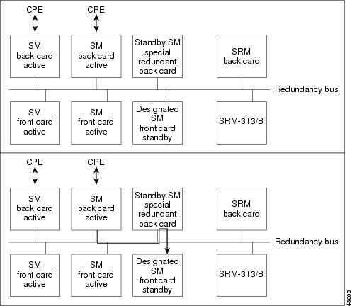
One of the major functions of the SRM-3T3/C is to provide 1:N redundancy. Figure 4-7 illustrates 1:N redundancy. The upper part of the illustration show the FRSM-8T1 in slot 6 has been configured to provide 1:N redundancy for the FRSM-8T1s in slots 4 and 5. In the bottom part, the FRSM-8T1 in slot 5 has failed and the one in slot 6 has taken over for the failed service module.
Figure 4-7 1:N Redundancy
1:N Redundancy
Currently, 1:N redundancy is only supported for the 8-port T1/E1 cards (for example, FRSM-8T1, 8E1, 8T1-C and 8E1-C). A 1:N redundancy support for the T3/E3 cards would require a new SRM.
If the system has an SRM-3T3/C, 1:N redundancy can be specified for 8T1/E1 service modules. With 1:N redundancy, a group of service modules has one standby module. When an active card in a group fails, the SRM-3T3/C invokes 1:N redundancy for the group. The back card of the failed service module subsequently directs data to and from the standby service module using the redundancy bus. The SRM-3T3/C can support multiple group failures if the service modules are configured in bulk mode. In this case, the SRM reroutes the T1 data from the failed card to the standby card using the distribution bus.
The standby service module uses a special, redundant version of the back card. The module number of the redundant back card begins with an "R," as in "AX-R-RJ48-8T1".
When the failed card is replaced, switch back to normal operation. The switch does not automatically do so.
1:1 Redundancy
A 1:1 redundancy is NOT a feature of the SRM. This type of redundancy requires a pair of card sets with a Y-cable for each active line and its redundant standby. Specify one set as active and one set as standby. The configuration is card-level rather than port-level.
SM Redundancy with Line Modules
Nonbulk mode distribution is a mode of operation where individual T1 lines are directly connected to the line module of each front card. During normal nonbulk mode operation, the T1/E1 data flow is from the service module's line module to its front card and vice-versa. The line modules also contain isolation relays that switch the physical interface signals to a common redundancy bus under SRM-3T3 control in case of service module failure.
When a service module is detected to have failed, the PXM1 will initiate a switchover to the standby service module. The relays on the service module's line module (all T1/E1s) are switched to drive the signals onto the T1 redundancy bus. The designated standby card's line module (controlled by the SRM-3T3) receives these signals on the T1/E1 redundancy bus. The data path then is from the failed service modules' line module to the T1/E1 redundancy bus to the line module of the standby service module and finally to the standby service module itself. The service module redundancy data path is shown in Figure 4-8.
Figure 4-8 SM Redundancy with Line Modules
Line module redundancy is not offered since there are no service affecting active devices.
In nonbulk mode, the SRM-3T3 will control the data path relays on the service module's line modules.
The 1:N redundancy is limited to the service bay that the SRM and the service modules are located in. Therefore, each active SRM provides redundancy for a maximum of 8 service modules.
Bulk Mode Distribution/Redundancy
Bulk distribution is a mode of operation in which individual lines are not brought to service modules, but instead the these lines are multiplexed into a few high-speed lines attached to the SRM. The SRM then takes this "bulk" interface, extracts the lines, and distributes them to the service modules. Any cards served by this bulk interface can participate in 1:N redundancy without using the separate redundancy bus. Any T1 in a T3 line can be distributed to any eight ports on a service module in any slots of the service bay without restriction.
The 1:N redundancy is limited to the service bay that the SRM and the service modules are located in.
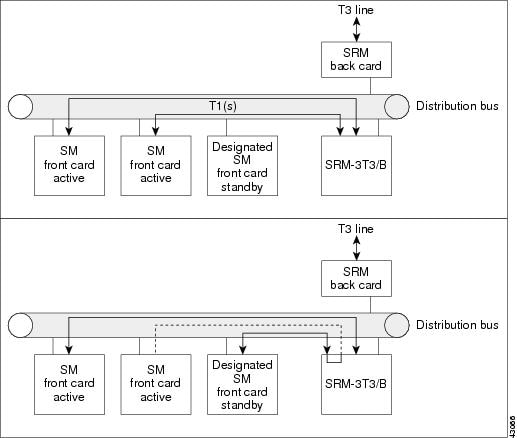
During bulk mode operation, the SRM-3T3/B unbundles T1 data from the incoming T3s and sends it to each service module (see Figure 4-9). Any slot can be used to process T1 data or to house a standby service module. When a service module fails, the PXM1 initiates a switchover to a previously configured standby module. The SRM-3T3/C will redirect the recovered T1 traffic to the designated standby module. The switching takes place inside the SRM-3T3/C and requires no special back cards or cabling. The data path to the standby module is still via the Distribution Bus. The Redundancy Bus is NOT used in bulk mode.
The current SRM can support 64 T1/E1s.
Figure 4-9 Bulk Mode Distribution/Redundancy
Loopbacks
The MGX 8230 supports many different types of loops for performance testing. The loop types supported on a card are dependent on the card type and line type. There are three types of loops supported:
•
•
•
Local line loops can also be initiated on the T1/E1 service modules via the addlnloop command. On the T3 service modules, the addds3loop command would be entered. All three line loops are supported by the SRM.
BERT Data Path
The SRM-3T3/C card performs BERT pattern generation and checking for the DS1/DS0 stream. This function is completely separate from the 3T3 distribution features of the SRM-3T3.
The SRM can support BERT on only one line or port at a time. BERT is capable of generating a variety of test patterns, including all ones, all zeros, alternate one zero, double alternate one zero, 223-1, 220-1, 215-1, 211-1, 29-1, 1 in 8, 1 in 24, DDS1, DDS2, DDS3, DDS4, and DDS5.
The BERT bus is used to provide the BERT operation to the individual service modules. This bus is also used to drive special codes such as fractional T1 loopback codes, and so on, onto the T1 line. The BERT function is initiated ONLY on one logical T1/E1 N x 64K port per MGX 8230 at any given time and this is controlled by the PXM1. The SRM-3T3 ensures that the BERT patterns are generated and monitored (if applicable) at the appropriate time slots.
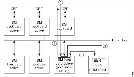
The datapath then for that particular port (N x 64K) is from the service module to the SRM-3T3/C (via the BERT bus) and back to the service module (via the BERT bus). On the service module, the data that is transmitted is switched between the regular data and the BERT data at the appropriate timeslots as needed. Similarly in the receive direction, the received data is diverted to the BERT logic for comparison during appropriate time slots. The illustration in Figure 4-10 shows the datapath for BERT and loopback operations via the SRM-3T3 module.
Figure 4-10 BERT Data Path
The BERT logic is self-synchronizing to the expected data. It also reports the number of errors for bit error rate calculation purposes.
BERT testing requires the presence of an SRM-3T3/C card in the service bay in which the card under test is located. The BERT tests can only be initiated by CLI.
Caution
Route Processor Module
The Cisco MGX 8230 Route Processor module (RPM) provides a new dimension in its industry-leading service breadth, providing integrated IP in an ATM platform, enabling services such as integrated Point-to-Point (PPP) protocol and Frame Relay termination and IP virtual private networks (VPNs). The full IOS enables the IP services for RPM.
The Route Processor Module on an MGX 8230 is a Cisco 7200 series router redesigned to fit onto a single double-height card that fits into an MGX 8230 chassis.
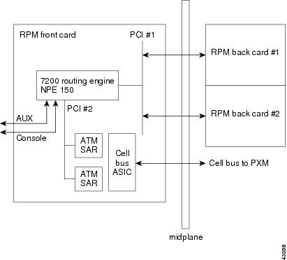
The module fits into the MGX 8230 midplane architecture, with the RPM front card providing a Cisco IOS network processing engine (NPE-150), capable of processing up to 140K packets per second (pps). The front card also provides ATM connectivity to the MGX 8230 internal cell bus at full-duplex OC-3c/STM-1 from the module. Each module supports two single-height back cards. Initially, three single-height back-card types will be supported: four-port Ethernet, one-port (FDDI), and one-port Fast Ethernet.
The RPM enables high-quality, scalable IP+ATM integration on the MGX 8230 platform using MPLS Tag Switching technology. Tag Switching combines the performance and virtual-circuit capabilities of Layer 2 switching with the proven scalability of Layer 3 networking and is the first technology to fully integrate routing and switching for a scalable IP environment.
Each RPM module supports two single-height back cards. Initially, three basic types of back-cards will be supported: four-port Ethernet, one-port (FDDI), and one-port Fast Ethernet.
The RPM can be ordered with 64M DRAM or 128M DRAM. The RPM currently has 4M of Flash Memory and does not support PCMCIA slots for Flash memory cards. The Cisco IOS image and configuration files are stored on the PXM1 hard drive or a network server.
FRSM to RPM Connection
From the FRSM, the frames are forwarded to the RPM via frame forwarding and FR-ATM Interworking, as illustrated in Figure 4-11.
Figure 4-11 FRSM to RPM Connection
Frame Aggregation: Port Forwarding
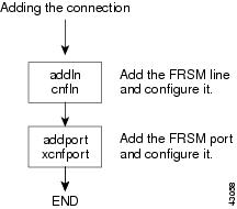
All frames received on a port are forwarded to the router for Layer 3 processing. For example, an FRSM T1 could be configured for PPP IP access by
1.
2.
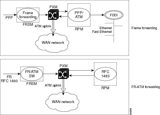
The data flow for a PPP connection destined for the RPM is shown in Figure 4-12. The packet enters the FRSM module as PPP and is frame forwarded to the RPM. The RPM receives the packet in PPP over ATM because the MGX 8230 internal connectivity is ATM. The RPM is running software that understands PPP over ATM encapsulation, allowing the router to reach the IP layer and route the packet to its destination (for example, the Internet). Packets destined to the Internet via a WAN network are then sent back to the PXM1, and out the ATM uplink.
Figure 4-12 FRSM to RPM Connection
FR-ATM Interworking
In this example, all frames received on a given connection are forwarded to the router using the appropriate ATM encapsulation. For example, Frame Relay connections on an FRSM port could be forwarded to the RPM by:
•
•
The data flow for a native Frame Relay connection destined to the RPM is shown in Figure 4-13. This data flow is identical to that of PPP packets, but the encapsulation techniques are different. Standard Frame Relay is encapsulated using RFC1490. When a packet is received at the FRSM encapsulated using RFC1490, standard FR-ATM service interworking translation mode (FRF.8) is performed so that when the packet is forwarded to the router blade it is encapsulated using RFC1483. The router also understands RFC1483, allowing it to reach the IP layer, and route the packet.
Tip
AUSM/B to RPM Connection
ATM UNI/NNI connection between the RPM and the AUSM/B is illustrated in Figure 4-13.
Figure 4-13 AUSM/B to RPM Connection
ATM Deluxe Integrated Port Adapter/Interface
The ATM Deluxe port adapter/interface is a permanent, internal ATM interface. The ATM Deluxe port adapter provides a single ATM interface to the MGX 8230 cell bus interface (CBI). Since it is an internal interface and resides on the RPM front card, it has no cabling to install and no interface types supported. It connects directly to the MGX 8230 midplane. (See Figure 4-14.)
The following features from the ATM Deluxe port adapter/interface are supported on the MGX 8230 switch:
•
•
•
•
•
•
Figure 4-14 ATM Deluxe Integrated Port Adapter
Figure 4-15 shows a block diagram of RPM front and back cards in an MGX 8230.
Figure 4-15 RPM Block Diagram